Louder Raspberry Pi is an open-source home media center based on a combination of the Raspberry Pi Zero W or Zero 2 W and the Texas Instruments TAS5805M DAC. It is an audio entertainment platform created by Andriy Malyshenko of Sonocotta, a Polish electronics hobbyist and maker.
Louder Raspberry Pi incorporates the computing power of the Raspberry Pi Zero and the Hi-Fi audio processing capabilities of TI’s TAS5805M DAC in a compact, aluminum case. The device delivers up to 25W per channel stere
Louder Raspberry Pi is an open-source home media center based on a combination of the Raspberry Pi Zero W or Zero 2 W and the Texas Instruments TAS5805M DAC. It is an audio entertainment platform created by Andriy Malyshenko of Sonocotta, a Polish electronics hobbyist and maker.
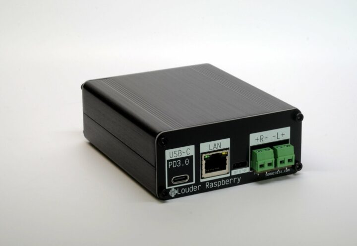
Louder Raspberry Pi incorporates the computing power of the Raspberry Pi Zero and the Hi-Fi audio processing capabilities of TI’s TAS5805M DAC in a compact, aluminum case. The device delivers up to 25W per channel stereo output and is powered via a 65W+ USB-C PD3.0 adapter. It is “aimed to be paired with medium-to-large speaker systems” and supports both Wi-Fi and Ethernet.
The Raspberry Pi board was selected over other lightweight alternatives due to the ease of development it offers. The Raspberry Pi Zero board is small enough to make for an overall compact device and powerful enough to handle the demands of a home media center.
Louder Raspberry Pi specifications:
SBC – Raspberry Pi Zero W or Raspberry Pi Zero 2W (Broadcom BCM2835 SoC single-core, 32-bit ARM11 @ 1GHz or Broadcom BCM2710A1 SoC quad-core ARM Cortex-A53 @ 1 GHz)
USB – 1x USB-C PD3.0 for power delivery and serial port
Audio Output – 2x 22W at 20V input over USB-PD
Misc – 1x IR reader, 2-pin speaker terminal
Power – 65W+ USB-C power adapter
Dimensions – 88 x 38 x 100mm
Louder Raspberry Pi is part of a line of Raspberry Pi-based media center devices from Sonocotta, a series that also includes Loud Raspberry Pi (work-in-progress) and Hi-Fi Raspberry Pi. You can set up your audio server using Volumio, Mopidy, or your favorite music player software. However, your operating system will need to be configured to work with the TAS5805M DAC. Instructions and associated code are available in a GitHub repository.
The device is priced at $35 for the base board and DAC on Tindie. The Raspberry Pi Zero W version costs $55 while the Zero 2 W version can be bought for $60. Adding a Lenovo 32GB Class 10 SD card incurs a $10 additional cost. If you want to build your own Louder Raspberry Pi, board schematics, PCB designs, and detailed information about the device are available in the Sonocotta media center repository.
ntttcp (Windows NT Test TCP) is a network benchmarking utility similar to iperf3 that works in both Windows and Linux written and recommended by Microsoft over iperf3, so we’ll test the alternative in this mini review.
iperf3 is a utility of choice for our reviews of single board computers and mini PCs running either Windows or Linux, but we’ve noticed that while Ethernet (up to 2.5GbE) usually performs just as well in Windows and Linux, WiFi is generally much faster in Ubuntu 22.04 than in Wind
ntttcp (Windows NT Test TCP) is a network benchmarking utility similar to iperf3 that works in both Windows and Linux written and recommended by Microsoft over iperf3, so we’ll test the alternative in this mini review.
iperf3 is a utility of choice for our reviews of single board computers and mini PCs running either Windows or Linux, but we’ve noticed that while Ethernet (up to 2.5GbE) usually performs just as well in Windows and Linux, WiFi is generally much faster in Ubuntu 22.04 than in Windows 11. So when XDA developers noticed a post by Microsoft saying iperf3 should not be used on Windows 11, it caught my attention.
Microsoft explains iperf3 should not be used in Windows for three main reasons:
The maintainer of iperf – ESnet (Energy Sciences Network) – says “iperf3 is not officially supported on Windows, but iperf2 is. We recommend you use iperf2. Some people are using Cygwin to run iperf3 in Windows, but not all options will work”
iPerf3 is Emulated on Windows – iPerf3 does not make Windows native API calls as it only knows how to make Linux/POSIX calls, and this may impact performance.
I usually download iperf3 3.1.3 for Windows released in 2016, and Microsoft notes the one offered by ESnet (version 3.16) is more recent but still 15 versions behind, so users are not running the latest version of the utilities.
So what’s the alternative for iperf3? Microsoft maintains two:
ntttcp (Windows NT Test TCP) open-source utility for Windows and Linux with a command line similar to iperf3 according to Microsoft in the sense it aims to isolate network stack throughput.
ctsTraffic for Windows-to-Windows testing only, also open-source and maintained on Github. ctsTraffic focuses on end-to-end goodput scenarios.
We can disqualify ctsTraffic immediately here at CNX Software since our tests typically involve a mix of Linux and Windows machines. Microsoft compared iperf3 to ntttcp utilities with high-speed network interfaces (10 GbE+), and the latter reports much higher performance. I only have hardware with 2.5GbE and WiFi 6, but I still wanted to test it, especially to check WiFi. So I decided to give ntttcp a try following the instructions on Microsoft Learn. It ended up being a challenge as those would not work on my system, and it took me a while to find the right parameters…
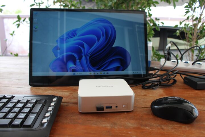
The Khadas Mind Premium was selected as it’s the only spare Windows system with 2.5GbE and WiFi 6 that I own and have already reviewed. You’ll notice the network tests in Windows 11 and Ubuntu 22.04 using iperf3 reveal much lower performance in the Microsoft OS as summarized in the table below.
WiFi 6 Tx
WiFi 6 Rx
2.5GbE Tx
2.5GbE Rx
WIndows 11 Home
712 Mbps
590 Mbps
700 Mbps
2.30 Gbps
Ubuntu 22.04
1.40 Gbps
991 Mbps
2.35 Gbps
2.35 Gbps
The Khadas mini PC is an outlier when it comes to 2.5GbE upload performance, but WiFi is faster in Linux in all mini PC reviews we’ve done. Since the Mind Premium review was done a while ago (August 2023), I updated Windows to the latest version and drivers and tested networking performance again with iperf3 and ntttcp in Windows 11 Home using the same command line as in the Microsoft blog post.
The first step was to install ntttcp (Linux) on UP Xtreme i11 mini PC running Ubuntu 20.04:
git clone https://github.com/microsoft/ntttcp-for-linux
cd ntttcp-for-linux/src
make
sudo make install
We can run the receiver command as follows.
devkit@UPX-i11:~/ntttcp-for-linux$ ntttcp -r -m 1,*,192.168.31.12 -t 60 -V
NTTTCP for Linux 1.4.0
---------------------------------------------------------
*** receiver role
ports:				 1
cpu affinity:			 *
server address:			 192.168.31.12
domain:				 IPv4
protocol:			 TCP
server port starting at:	 5001
receiver socket buffer (bytes):	 65536
test warm-up (sec):		 no
test duration (sec):		 60
test cool-down (sec):		 no
show system tcp retransmit:	 no
quiet mode:			 disabled
verbose mode:			 enabled
---------------------------------------------------------
12:25:30 DBG : user limits for maximum number of open files: soft: 1024; hard: 1048576
12:25:30 DBG : Interface:[lo]	Address: 127.0.0.1
12:25:30 DBG : Interface:[enp44s0]	Address: 192.168.31.12
12:25:30 DBG : Interface:[docker0]	Address: 172.17.0.1
12:25:30 DBG : Interface:[flannel.1]	Address: 10.42.0.0
12:25:30 DBG : Interface:[cni0]	Address: 10.42.0.1
12:25:30 INFO: 2 threads created
12:25:30 DBG : ntttcp server is listening on 192.168.31.12:5001
12:25:30 DBG : ntttcp server is listening on 192.168.31.12:5000
12:25:47 DBG : New connection: 192.168.31.69:50666 --> local:10000 [socket 6]
socket read error: 104
12:26:11 DBG : socket closed: 6
12:26:32 DBG : New connection: 192.168.31.69:50675 --> local:10000 [socket 6]
socket read error: 104
12:26:37 DBG : socket closed: 6
12:26:49 DBG : New connection: 192.168.31.69:50683 --> local:10000 [socket 6]
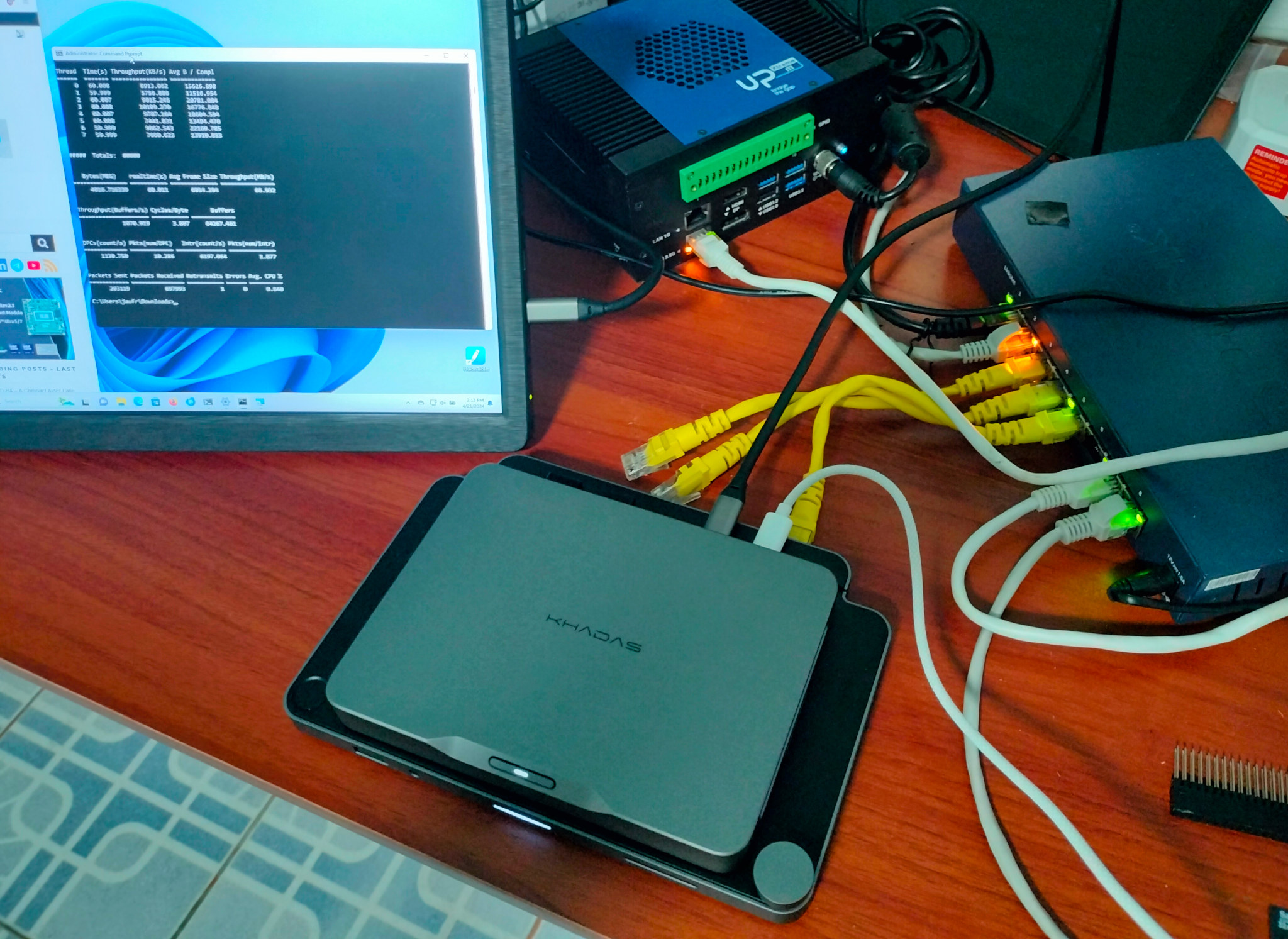
Only one core is used to emulate iperf3 and the V (verbose) options help a lot to troubleshoot issues. After downloading the ntttcp.exe binary to Windows we can run it immediately as a sender in a command prompt:
C:\Users\jaufr\Downloads>ntttcp.exe -s -m 1,*,192.168.31.12 -l 128K -t 60 -V
Copyright Version 5.39
buffers_length: 131072
num_buffers_to_send: 9223372036854775807
send_socket_buff: -1
recv_socket_buff: -1
port: 5001
sync_port: 0
no_sync: 0
wait_timeout_milliseconds: 600000
async_flag: 0
verbose_flag: 1
wsa_flag: 0
use_ipv6_flag: 0
send_flag: 1
udp_flag: 0
udp_unconnected_flag: 0
verify_data_flag: 0
wait_all_flag: 0
run_time: 60000
warmup_time: 0
cooldown_time: 0
dash_n_timeout: 10800000
bind_sender_flag: 0
sender_name:
max_active_threads: 1
no_delay: 0
node_affinity: -1
udp_uso_size: 0
udp_receive_coalescing: 0
tp_flag: 0
use_hvsocket_flag: 0
no_stdio_buffer: 0
throughput_Bpms: 0
cpu_burn: 0
latency_measurement: 0
use_io_compl_ports: 0
cpu_from_idle_flag: 0
get_estats: 0
qos_flag: 0
packet_period: 0
jitter_measurement: 0
mapping[0]: 1
4/21/2024 10:10:45 proc_speed: 2611 MHz
4/21/2024 10:10:45 SetupThreads
4/21/2024 10:10:45 Threads: 1   Processor: -1   Host: 192.168.31.12
4/21/2024 10:10:45 created thread 0 port 5001
4/21/2024 10:10:45 StartSenderReceiver start thread 0 port 5001
4/21/2024 10:10:45 SetupNet port 5001
4/21/2024 10:10:45 connected to port 5001
4/21/2024 10:10:45 SetupNet complete on port 5001
4/21/2024 10:10:45 All threads ready!
4/21/2024 10:10:45 SetupNet port 6001
4/21/2024 10:10:47 ERROR: SetupNet failed: Connect attempt failed, GetLastError: 10061 - No connection could be made because the target machine actively refused it.
4/21/2024 10:10:47 PORT#: 6001
4/21/2024 10:10:49 ERROR: SetupNet failed: Connect attempt failed, GetLastError: 10061 - No connection could be made because the target machine actively refused it.
But as you can see from the log above, it did not quite work as expected. It turns out that for Windows to Linux tests, we need to use the “ns” (No Sync) parameter. It’s mentioned in the Microsoft’s blog post
There is a known interoperability limitation when testing between Windows and Linux. Details can be found in this ntttcp for Linux wiki article on GitHub.
It took me a couple of hours to find out, but once I did that, I could complete the WiFi 6 Tx (upload) test:
88 MB/s or 704 Mbps, so it’s basically the same as with iperf3 even after having updated the drivers.
iperf3 has a reverse transfer option, but I could not see any such option on ntttcp. So I had to type the commands to run ntttcp.exe in receiver mode on Windows and ntttcp in sender mode on Linux. We’ll need to run CMD as administrator, open the firewall, and the networking benchmark tool with other parameters:
The Linux command for the Ubuntu sender is quite different than the same command for the Windows sender as parameters are different:
devkit@UPX-i11:~/ntttcp-for-linux$ ntttcp -s -m 1,*,192.168.31.141 -b 128K -N -t 60 -V
NTTTCP for Linux 1.4.0
---------------------------------------------------------
*** sender role
*** no sender/receiver synch
connections:			 1 X 1 X 1
cpu affinity:			 *
server address:			 192.168.31.141
domain:				 IPv4
protocol:			 TCP
server port starting at:	 5001
sender socket buffer (bytes):	 131072
test warm-up (sec):		 no
test duration (sec):		 60
test cool-down (sec):		 no
show system tcp retransmit:	 no
quiet mode:			 disabled
verbose mode:			 enabled
---------------------------------------------------------
14:45:55 DBG : user limits for maximum number of open files: soft: 4096; hard: 4096
14:45:55 INFO: Starting sender activity (no sync) ...
14:45:55 INFO: 1 threads created
14:45:55 DBG : New connection: local:42880 [socket:3] --> 192.168.31.141:5001
14:45:55 INFO: 1 connections created in 1708 microseconds
14:46:55 INFO: Test run completed.
14:46:55 INFO: Test cycle finished.
14:46:55 INFO: 	Thread	Time(s)	Throughput
14:46:55 INFO: 	======	=======	==========
14:46:55 INFO: 	0	 60.00	 2.28Gbps
14:46:55 INFO: 1 connections tested
14:46:55 INFO: #####  Totals:  #####
14:46:55 INFO: test duration	:60.00 seconds
14:46:55 INFO: total bytes	:17068195840
14:46:55 INFO: 	 throughput	:2.28Gbps
14:46:55 INFO: 	 retrans segs	:54998
14:46:55 INFO: cpu cores	:8
14:46:55 INFO: 	 cpu speed	:2000.462MHz
14:46:55 INFO: 	 user		:0.46%
14:46:55 INFO: 	 system		:0.78%
14:46:55 INFO: 	 idle		:97.94%
14:46:55 INFO: 	 iowait		:0.00%
14:46:55 INFO: 	 softirq	:0.82%
14:46:55 INFO: 	 cycles/byte	:1.16
14:46:55 INFO: cpu busy (all)	:5.16%
14:46:55 INFO: tcpi rtt		:397 us
But I still managed it. Needless to say, I did have an overly positive view of ntttcp utility so far. The only benefit I see is that we have some extra data such as CPU usage during the transfer. 2.28 Gbps is about what we would expect for a 2.5GbE connection.
I usually disconnect the Ethernet cable to test WiFi 6 with iperf3 and run the same command. But here we also need to change the IP address on both the server and client side to test it again:
devkit@UPX-i11:~/ntttcp-for-linux$ ntttcp -s -m 1,*,192.168.31.69 -b 128K -N -t 60
NTTTCP for Linux 1.4.0
---------------------------------------------------------
14:54:58 INFO: Starting sender activity (no sync) ...
14:54:58 INFO: 1 threads created
14:54:58 INFO: 1 connections created in 6716 microseconds
14:55:58 INFO: Test run completed.
14:55:58 INFO: Test cycle finished.
14:55:58 INFO: 1 connections tested
14:55:58 INFO: #####  Totals:  #####
14:55:58 INFO: test duration	:60.00 seconds
14:55:58 INFO: total bytes	:4530110464
14:55:58 INFO: 	 throughput	:604.01Mbps
14:55:58 INFO: 	 retrans segs	:0
14:55:58 INFO: cpu cores	:8
14:55:58 INFO: 	 cpu speed	:2800.000MHz
14:55:58 INFO: 	 user		:0.53%
14:55:58 INFO: 	 system		:0.41%
14:55:58 INFO: 	 idle		:99.01%
14:55:58 INFO: 	 iowait		:0.00%
14:55:58 INFO: 	 softirq	:0.04%
14:55:58 INFO: 	 cycles/byte	:2.93
14:55:58 INFO: cpu busy (all)	:1.98%
604 Mbps so there’s no improvement here.
WiFi 6 Tx
WiFi 6 Rx
2.5GbE Tx
2.5GbE Rx
iperf3
551 Mbps
608 Mbps
736 Mbps
2.30 Gbps
ntttcp
785 Mbps
604 Mbps
704 Mbps
2.28 Gbps
The table above summarizes the results after I ran iperf3 again. While ntttcp is faster for WiFi 6 upload, the results are not conclusive as the other results are more or less unchanged. I suppose it only matters for high-speed networking with 10GbE or greater connections.
The tests above were done to compare ntttcp to iperf3 with similar parameters, but Microsoft says multithread and larger buffer sizes should be used to test bandwidth. Let’s try again with WiFi 6 download using 8 threads and 1024KB buffer size:
devkit@UPX-i11:~/ntttcp-for-linux$ ntttcp -s -m 8,*,192.168.31.69 -b 1024K -N -t 60
NTTTCP for Linux 1.4.0
---------------------------------------------------------
15:00:06 INFO: Starting sender activity (no sync) ...
15:00:06 INFO: 8 threads created
15:00:06 INFO: 8 connections created in 5242 microseconds
15:01:06 INFO: Test run completed.
15:01:06 INFO: Test cycle finished.
15:01:06 INFO: 8 connections tested
15:01:06 INFO: #####  Totals:  #####
15:01:06 INFO: test duration	:60.00 seconds
15:01:06 INFO: total bytes	:4234149888
15:01:06 INFO: 	 throughput	:564.55Mbps
15:01:06 INFO: 	 retrans segs	:573
15:01:06 INFO: cpu cores	:8
15:01:06 INFO: 	 cpu speed	:2800.000MHz
15:01:06 INFO: 	 user		:0.52%
15:01:06 INFO: 	 system		:0.54%
15:01:06 INFO: 	 idle		:98.62%
15:01:06 INFO: 	 iowait		:0.00%
15:01:06 INFO: 	 softirq	:0.32%
15:01:06 INFO: 	 cycles/byte	:4.39
15:01:06 INFO: cpu busy (all)	:2.90%
---------------------------------------------------------
564 Mbps is slower than with only one thread and a 128KB buffer, although I reckon WiFi results can be fairly volatile.
Based on the tests done above there’s very little difference between iperf3 and ntttcp results, ntttcp Linux has not been updated for over three years, so I’m not convinced, and we’ll keep using iperf3 for the networking tests in reviews of Windows mini PCs…
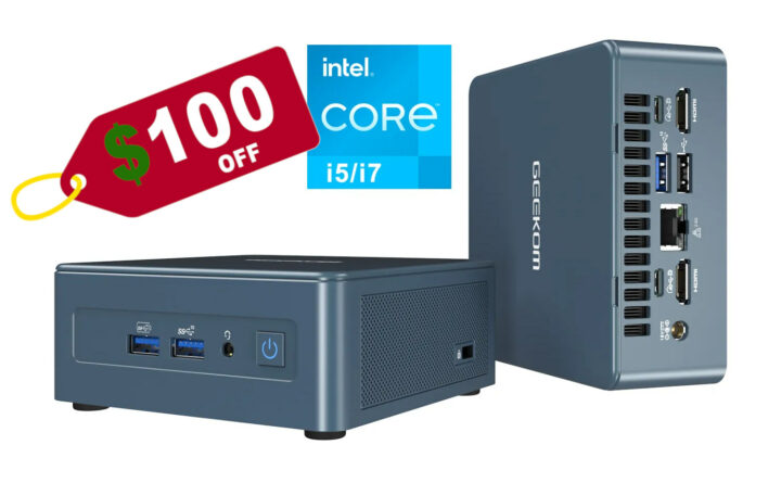
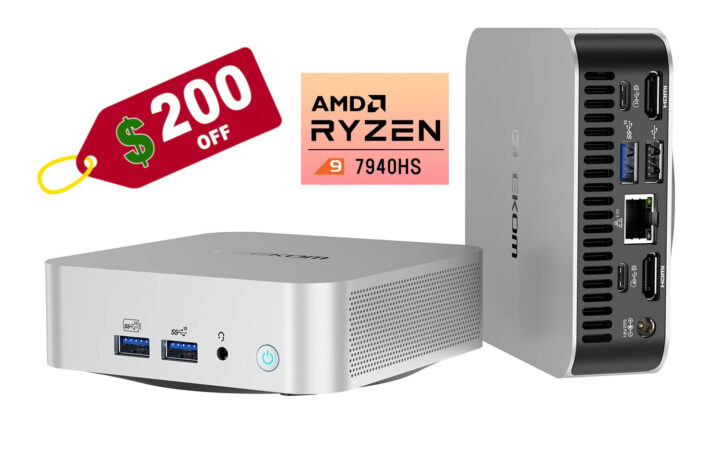
Following the ongoing $200 off promotion for the powerful GEEKOM A7 mini PC, GEEKOM is now offering another discount for its mid-range Mini IT12 mini PC powered by an Intel Core i5-12450H processor with 16GB RAM and a 512GB M.2 2280 NVMe SSD storage that is now sold for $349 – the lowest price ever – instead of $449, when using the coupon code cnxit12off on GEEKOM US or GEEKOM UK for a $100 discount.
While it’s a mid-range mini PC, it still comes with premium features such as two USB4 ports cap
Following the ongoing $200 off promotion for the powerful GEEKOM A7 mini PC, GEEKOM is now offering another discount for its mid-range Mini IT12 mini PC powered by an Intel Core i5-12450H processor with 16GB RAM and a 512GB M.2 2280 NVMe SSD storage that is now sold for $349 – the lowest price ever – instead of $449, when using the coupon code cnxit12off on GEEKOM US or GEEKOM UKfor a $100 discount.
While it’s a mid-range mini PC, it still comes with premium features such as two USB4 ports capable of 40 Gbps transfer rate and DisplayPort Alt. mode video output or 2.5GbE and WiFi 6E networking. The GEEKOM Mini IT12 (Core i5-12450H) mini PC also supports up to four 4K displays through HDMI and USB4 ports, additional storage thanks to an M.2 2242 SATA socket and a a 2.5-inch SATA slot, and comes with a total of six USB ports for expansion.
GEEKOM Mini IT12 specifications:
SoC – Intel Core i5-12450H 8-core/12-thread Alder Lake hybrid processor up to 4.40 GHz with 12MB Cache, 48 EU Intel UHD Graphics @ up to 1.2 GHz; PBP: 45W
System Memory – 16GB DDR4-3200 via SODIMM sockets upgradeable up to 64GB
Storage
512GB M.2 2280 PCIe Gen 4 x4 SSD, expandable up to 2TB
M.2 2242 SATA SSD socket up to 1TB
SATA slot for 2.5-inch drives up to 7mm thick, up to 2TB
Full-size SD card reader
Video Output – 2x HDMI 2.0 ports, 2x DisplayPort up to 8Kp60 via USB4 ports
Audio – 3.5mm audio jack, digital audio output via HDMI and DisplayPort
Networking
2.5GbE RJ45 jack
WiFi 6E and Bluetooth 5.2 via Intel AX211 wireless module
USB
2x USB4 ports (40 Gbps)
3x USB 3.2 Gen 2 ports (10 Gbps)
1x USB 2.0 port
Misc – Power button, Kensington Lock slot
Power Supply – 19V/6.32A (90W) via DC jack
Dimensions – 117 x 112 x 45.6 mm
Weight – 652 grams
The Mini IT12 mini PC comes pre-loaded with Windows 11 Pro and ships with a VESA mount, a power adapter, an HDMI cable, a user guide, and a Thank You card. While we haven’t had the chance to test the Mini IT12 with the Intel Core i5-12450H CPU, we did review the Mini IT12 Core i7-12650H model – its big brother with the same ports – with both Windows 11 Pro and Ubuntu 22.04. It worked great for office work and web browsing, YouTube video playback worked fine up to 8Kp60, and the USB4, 2.5GbE, and WiFi 6 worked up to expectation, but the GPU was a little on the low side, and multi-core performance could have been better. The cheaper Intel Core i5-12450H model will be slightly slower, but still offers great single-core performance and benefits from the same high-speed ports and interfaces.
The $349 price tag is valid until the cnxit12off coupon code expires on May 5, 2024. As with all mini PCs sold on the GEEKOM website, customers benefit from free local shipping from a US or UK warehouse, a 30-day return and refund period, and a 3-year warranty.
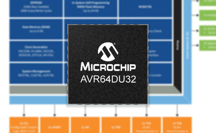
At Embedded World 2024, Microchip announced their new AVR DU family of 8-bit MCUs featuring a full-speed USB 2.0 data interface along with USB-C 15W Power Delivery enabling up to 12Mbps data transfer and charging. They also have features like secure bootloaders and Program and Debug Interface Disable (PDID), which protect your embedded designs.
Based on the Harvard architecture, these MCUs can have up to 64 KB of Flash memory, 8 KB of SRAM, and 256 bytes of EEPROM. Their wide operating voltage r
At Embedded World 2024, Microchip announced their new AVR DU family of 8-bit MCUs featuring a full-speed USB 2.0 data interface along with USB-C 15W Power Delivery enabling up to 12Mbps data transfer and charging. They also have features like secure bootloaders and Program and Debug Interface Disable (PDID), which protect your embedded designs.
Based on the Harvard architecture, these MCUs can have up to 64 KB of Flash memory, 8 KB of SRAM, and 256 bytes of EEPROM. Their wide operating voltage range of 1.8V to 5.5V makes them suitable for small, space-sensitive devices, power bricks, and rechargeable devices. But one thing to note is that the USB function is only available for VDD above 3.0V and I2C Fm+ (Fast-mode Plus) is only supported for 2.7V and above.
I²C Fm+ extends the standard I²C protocol, boosting communication speeds up to 1 MHz while maintaining compatibility with older I²C devices. It’s a simple upgrade for faster data transfer in applications using sensors, memory, and other I²C devices. This is not the first 8-bit MCU that Microchip has announced, previously we have seen MCUs like PIC16F13145 series, PIC18-Q24 8-bit MCU, and PIC18-Q20. Feel free to check those out if you are looking for 8-bit MCUs.
Event System for CPU-independent inter-peripheral signaling
Configurable Custom Logic (CCL) with four programmable Look-up Tables (LUTs)
Internal voltage references and external reference option (VREF)
I/O and Packages
Up to 25 programmable GPIO pins
Various package options including VQFN, TQFP, SPDIP, SSOP, and SOIC
Temperature Range – Industrial: -40°C to +85°C
Note! The above specs are for the AVR64DU32, the most feature-rich MCU in the family. While many specifications remain consistent across the series, some may vary depending on your specific MCU.
AVR DU Family block diagram – Shows maximum number of peripherals and memory
The DU family features compact 14 to 32-pin MCUs with varying RAM and flash sizes and has features like Configurable Custom Logic (CCL) with four programmable Look-up Tables (LUTs) for Simplified designs, flexible signal control, and Custom protocol support.
Customizable Logic is somewhat similar to programmable logic devices (PLDs), and it’s a key feature in Microchip’s latest MCUs. Configurable Logic Blocks (CLBs) allow you to program logic functions (AND, OR, XOR, etc.) using look-up tables (LUTs). This lets you design custom circuits within the MCU, reducing costs and power consumption compared to using separate components.
Microchip Dev Board Built Around AVR DU Family
To further simplify the development process, Microchip has also released the $24 AVR64DU32 Curiosity Nano, a development board built around the AVR64DU32 MCU. The Curiosity Nano from Microchip is a common platform for development boards that supports a wide range of microcontrollers.
The MCUs are fully compatible with the MPLAB X IDE and MPLAB XC8 C compiler. Additionally, the MPLAB Code Configurator (MCC) includes a USB software stack to manage the MCU’s USB hardware. The company also provides a getting-started guide and sample codes
More information about the AVR DU Family can be found on their product page. You can also find this microcontroller on Microchipdirect and DigiKey.
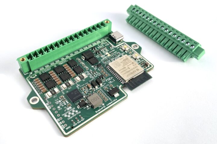
European engineer, Matej Planinšek of PLab, has developed the FOCn — a medium-power BLDC driver module based on ESP32-S3 WiSoC capable of delivering up to 10A of continuous current. It is compatible with the SimpleFOC Arduino library making it easier to control BLDC (brushless direct current) and stepper motors with the field-oriented control algorithm.
The developer was inspired to create the FOCn module when their search for a custom-made, SimpleFOC-compatible driver module that met all their
European engineer, Matej Planinšek of PLab, has developed the FOCn — a medium-power BLDC driver module based on ESP32-S3 WiSoC capable of delivering up to 10A of continuous current. It is compatible with the SimpleFOC Arduino library making it easier to control BLDC (brushless direct current) and stepper motors with the field-oriented control algorithm.
The developer was inspired to create the FOCn module when their search for a custom-made, SimpleFOC-compatible driver module that met all their requirements failed. The name is related to field-oriented control (FOC) and also means “face slap” in Slovenian, Matej’s native language.
The driver module is based on the ESP32-S3 dual-core XTensa LX7 microcontroller which provides Wi-Fi and Bluetooth connectivity. The microcontroller further supports ESP-NOW, a low-power and low-latency communication protocol, which makes it possible for multiple FOCn boards to talk to one another.
The USB-C port on the board can be used to program and debug the driver module. Extra cooling (heat sink or cooling fan) may be required in situations that require prolonged high motor current currents (>10A) and high ambient temperatures (>35°C).
The FOCn project is completely open-source. 3D models, schematics, Altium files, and documentation for the project are hosted on the FOCn GitHub repository, together with a PlatformIO project example. For more information about the driver module, you can refer to the earlier-mentioned repository or the project page on Hackaday. It is available for purchase on Tindie for $64.
Tomeu Vizoso has been working on an open-source driver for NPU (Neural Processing Unit) found in Rockchip RK3588 SoC in the last couple of months, and the project has nicely progressed with object detection working fine at 30 fps using the SSDLite MobileDet model and just one of the three cores from the AI accelerator.
Many recent processors include AI accelerators that work with closed-source drivers, but we had already seen reverse-engineering works on the Allwinner V831’s NPU a few years ago,
Tomeu Vizoso has been working on an open-source driver for NPU (Neural Processing Unit) found in Rockchip RK3588 SoC in the last couple of months, and the project has nicely progressed with object detection working fine at 30 fps using the SSDLite MobileDet model and just one of the three cores from the AI accelerator.
He started his work in March leveraging the reverse-engineering work already done by Pierre-Hugues Husson and Jasbir Matharu and was quickly able to run TensorFLow Lite’s Conv2D and DepthwiseConv2D operations. Only two weeks later, MobileNetv1 model could run on the Pine64 QuartzPro64 SBC with the same performance level as the blob (closed-source binary).
Work was much easier than on the Verisilicon Vivante NPU because lots of the reverse-engineering work was done, and NVDLA is open-source so at least some documentation was available, which was not the case for the Vivante NPU. Nevertheless, it took only four weeks (not full-time) to have the object detection shown below work on the Rockchip RK3588’s NPU at 30 FPS.
You’ll find the source code for the Teflon project on Freedesktop website, and you can also the status of the project on Tomeu’s blog. Next up, Tomeu plans to write a kernel driver for Linux mainline in the drivers/accel subsystem. There’s still much work to be done and it’s unclear how long it will take, especially since he is working on different NPUs and will split his time between each implementation unless additional contributors join the project(s).
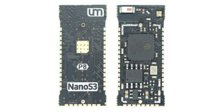
Seon Rozenblum, better known as Unexpected Maker, has launched NANOS3 a development board that claims to be the world’s smallest, fully-featured ESP32-S3 module! This new module packs all the peripherals, and wireless connectivity features of an ESP32-S3 while being even smaller than the TinyPICO Nano. The module features two variants one with an onboard 3D antenna and the other with an u.FL connector.
Previously we have written about TinyS3, FeatherS3, and ProS3 boards from Unexpected Maker we
Seon Rozenblum, better known as Unexpected Maker, has launched NANOS3 a development board that claims to be the world’s smallest, fully-featured ESP32-S3 module! This new module packs all the peripherals, and wireless connectivity features of an ESP32-S3 while being even smaller than the TinyPICO Nano. The module features two variants one with an onboard 3D antenna and the other with an u.FL connector.
MCU – ESP32-S3 dual-core Tensilica LX7 up to 240 MHz with 512KB SRAM, 16 KB RTC SRAM
Memory – 2MB QSPI PSRAM
Storage – 8MB QSPI flash
Wireless – WiFi 4 and Bluetooth 5 LE + Mesh;
I/O
2x 12-bit ADC
3 DAC
5x TX/RX PWM channels
Onboard RGB LED
NeoPixel Support (up to 1515 Neopixels)
27x GPIO broken out with 1.27mm pitch castellated edges
JTAG Support
D+/D- pins for external USB connector
Power
700mA 3.3V LDO Regulator
LiPo Battery Charging
Optimized power path for low-power battery usage
Antenna – Onboard 3D high gain antenna or external u.FL connector
Dimensions – 28 x 11 mm (the TinyPico Nano mesures 27 x 13 mm)
Release Date – July 2023
Unexpected Maker NANOS3 Pinout and Annotations
For simplicity, the company provides a pinout diagram along with parts annotation for the board. The pinout also shows USB and external Vin connections, making it easy to get started.
The NanoS3 ships with a UF2 bootloader and pre-installed CircuitPython, allowing for easy firmware updates. Other than that the board can also be programmed with MicroPython, ESP-IDF, and Arduino IDE. The company also provides a getting started guide for those who what to build applications around this board.
The board is completely open-sourced so files like 3D STEP files, KiCAD symbols and footprints, reference designs, PDF schematics, high-resolution pinout references, and much more can be found on the Unexpected Maker ESP32-S3 GitHub repository.
NanoS3 Carrier Board
The is priced at USD$19.00 and can be found on Unexpected Makers web store, In the store you can also get an External uFL Antenna just for $1. For additional details and a comparison between the NanoS3 and TinyPICO Nano, visit their product page.
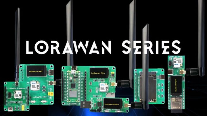
UK-based hardware developer, SB Components, has designed a new LoRaWAN product series (gateways and nodes) for the Raspberry Pi SBCs, Raspberry Pi Pico, ESP32, and other hardware, based on RAKWireless RAK5146 and RAK3172 modules.
The products are available in up to five variants (plus two relay boards) and are built to cater to hobbyists with different needs. They support several LoRaWAN server platforms including The Things Stack, Chirpstack, and Helium, with adaptive spreading factors, coding
UK-based hardware developer, SB Components, has designed a new LoRaWAN product series (gateways and nodes) for the Raspberry Pi SBCs, Raspberry Pi Pico, ESP32, and other hardware, based on RAKWireless RAK5146 and RAK3172 modules.
The products are available in up to five variants (plus two relay boards) and are built to cater to hobbyists with different needs. They support several LoRaWAN server platforms including The Things Stack, Chirpstack, and Helium, with adaptive spreading factors, coding rates, and bandwidth configurations.
The LoRaWAN products include:
Gateways – RAK5146 LoRaWAN Gateway HAT and RAK3172 LoRaWAN Gateway HAT for the Raspberry Pi SBCs
Nodes – RAK3172 LoRaWAN Module (Powered by Raspberry Pi Pico), Raspberry Pi RP2040 USB Dongle, RAK3172 LoRaWAN Module (powered by ESP32), LoRaWAN Breakout, GatePi LoRaWAN 4-Ch Relay, GatePi LoRaWAN 8-Ch Relay
LoRaWAN (long-range wide access network) uses the LoRa modulation technique to transmit data over large distances. In a LoRAWAN network, nodes are the devices that interface with other electronic components and collect data or perform actions within the IoT ecosystem while gateways transmit the data to the central network server for processing and analysis.
The relay boards, GatePi LoRaWAN 4-ch and 8-ch, are both powered by the RP2040 microcontroller chip with an RAK3172 transceiver module. They feature a “remote power switch” that can be used to turn on and control devices remotely and they can be used in industrial automation, home automation, and agriculture.
Fine Timestamp (enables simultaneous reception of up to 8 packets)
LoRaWAN frequency bands – EU868, CN470, US915, AS923, AU915, KR920, and IN865
RAK3172 LoRaWAN Node (Raspberry Pi Pico / USB Dongle / ESP32) specifications:
SoC
Raspberry Pi Pico/Pico W (Arm Cortex-M0 microcontroller @ 133 MHz with 264KB memory and 2MB storage); RAK3172 transceiver module based on STM32WLE5CC chip
ESP32-S3 series (Xtensa dual-core 32-bit LX7 microprocessor @ 240 MHz with 2.4 GHz Wi-Fi (802.11 b/g/n) and Bluetooth 5 (LE), 16MB storage, and 8MB memory); RAK3172 transceiver module based on STM32WLE5CC chip
Storage – microSD card for data logging
Display – 1.14-inch RGB TFT display, 240 x 135px, 65K/262K colors; ST7789 display driver via SPI interface
USB
LoRaWAN Node Expansion Board – USB Type-C for power and LoRa module configuration
LoRaWAN USB Dongle – Type A interface for programming and powering board
Pico/ESP32 GPIOs available for connecting sensors and actuators (absent on dongle)
Header breakout for configuring LoRa Module or standalone use with USB to TTL device (absent on expansion board)
Misc – 2x programmable buttons, onboard power status LED indicator, buzzer for audio alerts and notifications, boot and reset buttons (absent on dongle), battery connector (only ESP32 board)
RAK3172 LoRaWAN Gateway HAT / Breakout Module specifications:
Core – STM32WLE5CC microcontroller, Arm Cortex-M4 core @ 48MHz with 256KB flash memory and 64KB SRAM
HAT compatible with Raspberry Pi 40-pin header
1x SPI interface, 1x UART interface (easy-to-use AT command set)
Display – 1.14-inch RGB TFT display, 240 x 135px, 65K/262K colors; ST7789 display driver via SPI interface
1x USB Type C interface for standalone access to LPWAN module for configuration
SoC – RP2040 Arm Cortex-M0 microcontroller @ 133 MHz with 264KB memory and 2MB storage and RAK3172 transceiver module based on STM32WLE5CC chip
4-ch relays/8-ch relays
IPEX antenna connector
Remote Power Switch
The RAK3172 models use firmware based on RAKwireless Unified Interface V3 (RUI3), supporting the creation of different functionalities using RUI APIs, and recently open-sourced by the company.
The LoRaWAN series targets IoT applications, such as smart cities, agriculture, industry, public safety, and healthcare. Other recent products from SB Components include the Trekko Pico, Microflex MCUs, and Dual Roundy and Squary Displays, and the company also launched other LoRa/LoRaWAN in the past including the MessengerPi LoRa messenger and walkie-talkie and the Lo-Fi ESP32-S3 board.
The variants are priced from $34 to $156. The different prices are listed below:
LoRaWAN Breakout – $32
LoRaWAN Hat for Raspberry Pi – $34
LoRaWAN RP2040 USB Dongle – $47
LoRaWAN for Raspberry Pi Pico – $50
LoRaWAN for ESP32 – $50
GatePi LoRaWAN 4-ch relay – $50
GatePi LoRaWAN 8-ch relay – $65
LoRaWAN Gateway HAT – $165
SB Components has launched its LoRaWAN product series on Kickstarter with the crowdfunding campaign still having 15 days to go at the time of publication. The delivery of rewards is projected to commence by July 2024.
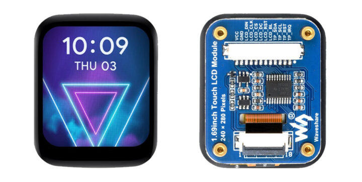
The Waveshare 1.69-inch IPS touch LCD is a 1.69-inch rounded display with 240×280 resolution and a 262K color range. The display driver (ST7789V2) and touch controller (CST816T) are integrated on-board and rely on SPI and I2C interfaces that make it compatible with popular platforms such as Raspberry Pi, Arduino, ESP32, STM32, and more.
Previously we have covered many similar display modules like the MaTouch ESP32-S3, T-RGB ESP32-S3, and ESP32-S3 Round SPI TFT. Feel free to check these out if yo
The Waveshare 1.69-inch IPS touch LCD is a 1.69-inch rounded display with 240×280 resolution and a 262K color range. The display driver (ST7789V2) and touch controller (CST816T) are integrated on-board and rely on SPI and I2C interfaces that make it compatible with popular platforms such as Raspberry Pi, Arduino, ESP32, STM32, and more.
Previously we have covered many similar display modules like the MaTouch ESP32-S3, T-RGB ESP32-S3, and ESP32-S3 Round SPI TFT. Feel free to check these out if you are looking for a specific rounded display product.
Waveshare 1.69-inch IPS touch LCD specifications
Display
1.69-inch round LCD with 240×280 resolution and IPS panel.
Onboard Logic Level Converter – Onboard voltage translator for 3.3V/5V power, works with Raspberry Pi, ESP32-S3, Raspberry Pi Pico, Arduino, STM32, and more.
Dimensions – 41.13 x 33.13 mm
The ST7789V2 LCD controller supports resolutions up to 240×320 pixels. Since this display’s resolution is 240×280, the internal RAM of the driver chip isn’t fully utilized, which means stable operation. The LCD supports 12-bit, 16-bit, and 18-bit color formats (RGB444, RGB565, RGB666). Additionally, it combines a scratch-resistant, high-transmittance toughened glass surface with a CST816D self-capacitance touch driver supporting a 10Khz~400Khz configurable communication rate. One issue this type of display has is that because of the four round corners, some parts of the input images may not be displayed.
For easy setup, the company provides schematic, datasheet, 2D and 3D drawings, along with example code for Raspberry Pi, Arduino, and STM32. All resources can be found on their Wiki page.
This module is available for purchase on both Amazon and the Waveshare store. On Amazon, it’s priced at $23.05 (including shipping), while on the Waveshare store, it costs $14.99. The one good thing that I liked about this module is that Waveshare offers a wider selection of similar displays, ranging from a compact 0.49-inch OLED Module to a larger 2.42-inch OLED Module. You can find their full range on both Amazon and the Waveshare store.
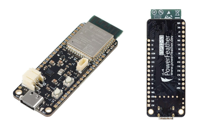
The ESP32-S3 PowerFeather board is an Adafruit Feather-shaped ESP32-S3 WiFi and BLE IoT board that can be powered by a Li-Ion or LiPo battery and supports up to 18V DC input for direct connection to a solar panel.
The developer told CNX Software that the main differentiating factor from other ESP32-S3 development boards was “its extensive power management and monitoring features” with a wide DC input range, supply and battery monitoring, and battery protection features.
ESP32-S3 PowerFeather sp
The ESP32-S3 PowerFeather board is an Adafruit Feather-shaped ESP32-S3 WiFi and BLE IoT board that can be powered by a Li-Ion or LiPo battery and supports up to 18V DC input for direct connection to a solar panel.
The developer told CNX Software that the main differentiating factor from other ESP32-S3 development boards was “its extensive power management and monitoring features” with a wide DC input range, supply and battery monitoring, and battery protection features.
ESP32-S3 PowerFeather specifications:
ESP32-S3-WROOM-1-N8R2
MCU – ESP32-S3 dual-core Tensilica LX7 up to 240 MHz with 512KB SRAM, 16 KB RTC SRAM
Memory – 2MB QSPI PSRAM
Storage – 8MB QSPI flash
Wireless – WiFi 4 and Bluetooth 5 LE + Mesh; PCB antenna
USB – 1x USB-C 1.1 OTG port for power and programming
Expansion
2x 16-pin 2.54 mm pitch headers with 23x multi-function GPIO:
Up to 4.2V/2A via 2-pin JST PH Li-ion/LiPo battery connector; BQ25628E battery charger
Maintained supply voltage (can be used to set MPP voltage)
Output
3.3V up to 1A shared between board, 3V3 header pin and VSQT STEMMA QT connector
3.3V to 4.2V up to 3A shared between board and VBAT header pin
3.8V to 18 V up to 2A shared between board and VS header pin
Torex XC6220 3.3V regulator
Monitoring
Supply – Current and voltage measurements, good supply detection
Battery – Voltage, current (charge/discharge), and temperature measurements; charge estimation; health & cycle count estimation; time-to-empty and time-to-full estimation; low charge, high/low voltage alarm; LC709204F fuel gauge
Battery protection
Undervoltage Detect @ 2.2 V, Release @ 2.4 V
Overvoltage Detect @ 4.37 V, Release @ 4.28 V
Overcurrent protection @ 3A
Trickle charging safety timer @ 1 hr
Temperature-based charging current reduction based on JEITA, cutoff at 0 °C and 50 °C.
Misc – 3V3 enable/disable; VSQT enable/disable
Power States – Ship mode, Shutdown mode, and Power cycle
Dimensions – 65 x 23 x 7 mm (Adafruit Feather form factor, supports Feather Wings); 2x 2.5 mounting holes
The documentation looks pretty good with a detailed hardware description, and instructions to get started with the Arduino IDE using the PowerFeather-SDK library or the ESP-IDF. Documentation for the SDK’s API and guides to connect a solar panel and lower power consumption are also provided.
We had previously written about an ESP32-C6 board that claimed to support solar charging, but the DC input range was only 4.5 – 6V, and several CNX Software readers were unimpressed. The ESP32-S3 PowerFeather provides an improvement with a 3.8V to 18V DC range, plus it supports “pseudo-MPPT”:
PowerFeather does not support ‘true’ MPPT in the sense that it does not do full tracking of the panel’s I-V curve. However, the panel MPP voltage can be set, and the charger IC will dynamically regulate charging current to prevent the panel voltage from collapsing below it. This provides near/pseudo-MPPT performance, since the MPP voltage for a typical panel remains roughly the same across various illumination levels.
The ESP32-S3 PowerFeather board can be purchased on Elecrow for $30, and there’s also a small solar panel ($22) and a PowerFeather ProtoWing ($7) board for sale. A few more details may also be found on the official website.
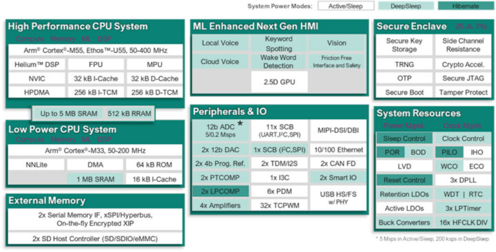
Infineon PSOC Edge E81, E83, and E84 MCU series are dual-core Cortex-M55/M33 microcontrollers with optional Arm Ethos U55 microNPU and 2.5D GPU designed for IoT, consumer, and industrial applications that could benefit from machine learning acceleration.
This is a follow-up to the utterly useless announcement by Infineon about PSoC Edge Cortex-M55/M33 microcontrollers in December 2023 with the new announcement introducing actual parts that people may use in their design. The PSOC Edge E81 series
Infineon PSOC Edge E81, E83, and E84 MCU series are dual-core Cortex-M55/M33 microcontrollers with optional Arm Ethos U55 microNPU and 2.5D GPU designed for IoT, consumer, and industrial applications that could benefit from machine learning acceleration.
This is a follow-up to the utterly useless announcement by Infineon about PSoC Edge Cortex-M55/M33 microcontrollers in December 2023 with the new announcement introducing actual parts that people may use in their design. The PSOC Edge E81 series is an entry-level ML microcontroller, the PSOC Edge E83 series adds more advanced machine learning with the Ethos-U55 microNPU, and the PSOC Edge E84 series further adds a 2.5D GPU for HMI applications.
Blog diagram for Infineon PSOC Edge E84 microcontroller
Arm Cortex-M55 high-performance CPU system up to 400 Mhz with FPU, MPU, Arm Helium support, 256KB i-TCM, 256KB D-TCM, 4MB SRAM (Edge E81/E83) or 5MB SRAM (Edge E84)
Arm Cortex-M33 low-power CPU system up to 200 MHz with 1MB SRAM, 64KB ROM
GPU (Edge 84 only) – Low-power 2.5D GPU
AI accelerators
All models – Infineon NNLite AI accelerator,
Edge E83 and E84 – Arm Ethos-U55 with 128 MACs, support for smart audio and computer vision (position detection, face recognition, object detection)
Storage – 2x SMIF, 2x SD host controllers
Display (Edge 84 only) – MIPI DSI/DBI up to 1024×768 resolution
Audio
All models
ULP Always ON progr. analog for voice, audio, sensing
4x analog mic, 6x digtial mic
NNLite wake word and acoustic activity detection
Edge 83/84 only – Ethos-U55-based wake word and acoustic activity detection, full voice inferencing
Networking – 10/100Mbps Ethernet
USB – USB HS/FS
Peripherals and I/Os – CAN Bus, SPI, UART, I2C, I3C, I2S, 12-bit ADC, etc…
Security – Secure enclave, Edge Protect category 2 and 4
Blurry photo of the PSOC Edge development kit…
The PSOC Edge family will be supported by the ModusToolbox software including board support packages (BSPs), peripheral driver library (PDL), middleware such as CAPSENSE, and integration with the Imagimob Studio AI solution and its off-the-shelf ML models called “Ready Models”. There’s limited information about the PSOC Edge development kit, but we do know it features a system-on-module, Arduino expansion headers, a sensor suite, BLE connectivity for provisioning, and Wi-Fi for smartphone and cloud connectivity. It was also showcased at Embedded World 2024 running a demo that can be seen in the video embedded below.
The PSOC Edge 81, 83, and 84-Series target appliances, speakers, wearables, robotics, and other smart home devices including connected IoT products. The PSOC Edge E81 provides entry-level ML computing for features such as anomaly detection, predictive maintenance, acoustic event detection, keyword spotting, wake word detection, voice prompts, and gesture/movement/presence detection. The Edge E83-series enables voice/audio wake-word detection with always-on acoustic activity detection mechanisms for battery-powered devices, while the PSOC Edge E84 can power similar applications with a graphical user interface.
The PSOC Edge family is only available to early-access customers for now, which may explain the lack of information and documentation. A few more details – including product briefs but not much else – may be found on the product page and in the press release.
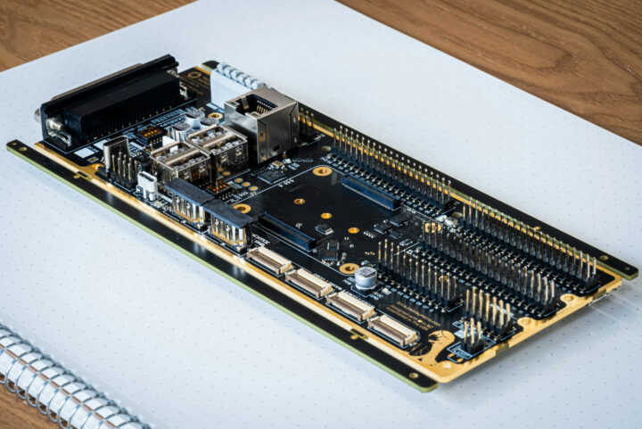
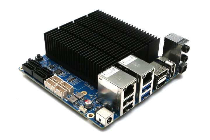
Paisley Microsystems PMC-C-CMX is a DIN-Rail mountable industrial control board taking a Raspberry Pi CM4 or CM5 (once launched), equipped with an STM32H7 Arm Cortex-M7 microcontroller for real-time control.
The carrier board integrates features such as wide voltage input (7 to 55V DC), an M.2 PCIe Gen 3 Key-B and Key-M sockets with cellular option, gigabit Ethernet, HDMI and MIPI DSI display interfaces, twp MIPI CSI camera interfaces, and several headers and connectors with RS485, GPIO, I2S, S
Paisley Microsystems PMC-C-CMX is a DIN-Rail mountable industrial control board taking a Raspberry Pi CM4 or CM5 (once launched), equipped with an STM32H7 Arm Cortex-M7 microcontroller for real-time control.
The carrier board integrates features such as wide voltage input (7 to 55V DC), an M.2 PCIe Gen 3 Key-B and Key-M sockets with cellular option, gigabit Ethernet, HDMI and MIPI DSI display interfaces, twp MIPI CSI camera interfaces, and several headers and connectors with RS485, GPIO, I2S, SPI, and more connected to either the Raspberry Pi Compute Module or the STM32H7 MCU.
Paisley Microsystems PMC-C-CMX specifications:
Supported system-on-modules – Raspberry Pi CM4 or upcoming Raspberry Pi CM5
MCU – STMicro STM32H7B0 Arm Cortex-M7 microcontroller up to 280 MHz with 128KB flash, 1.4MB SRAM
MCU <-> CM communication – UART and/or SPI
Video Output
2x HDMI ports up to 4Kp60
2x MIPI DSI connectors
Camera input – 2x MIPI CSI connectors
Networking
Gigabit Ethernet RJ45 port
Optional WiFi 5 and Bluetooth 5
Optional 4G LTE via M.2 B-key module and Nano SIM card
USB – 3x or 4x USB 2.0 ports (3x with popular PCIe B card)
Serial – RS485 up to 20 Mbps with PROFIBUS-DP support
Expansion
40-pin Raspberry Pi-compatible GPIO header
M.2 M-Key 2280 socket
M.2 B-Key 2230/3042/2280 socket with Nano SIM card slot (Note: only one M.2 socket can be used at a time due to Broadcom BCM2711/BCM2712 limitations)
STM32H7 headers with 70 GPIOs
25-pin “modular bus connector”
I2C, SPI, 8x GPIO
Power signals – 5V/2A, 3.3V/2A, 2x 6A Vin and 4x GND
Debugging – Dedicated SWD/ST-LINK interface
Misc – PCF85063AT RTC
Power Supply
7V to 55V DC up to 10A via 6-pin connector
9V/12V/20V up to 100W via USB-C PD port
Quiescent Power Consumption
Without Compute Module – 560 mW
With Raspberry Pi CM4 – 2,200 mW
Dimensions – 190.5 x 72.0 mm; DIN rail compatible
Temperature Range – -30 to +80°C
The Raspberry Pi CM4/CM runs Linux (Raspberry Pi OS) with logic/control/driving code and a hardware control middleware while the STM32H7 microcontroller runs C or ASM code to control GPIOs in real-time and communicate with the Compute Module over UART or SPI. A simple device control library, the middleware, and STM32H7 firmware will be provided by the company so that customers can focus on the higher-level parts of the software. At this time, I could not find much in the way of publicly available software documentation, but there are more details about the hardware on the documentation website.
Hardware & software overview/highlights
Paisley Microsystems sells the PMC-C-CMX industrial control board for Raspberry Pi CM4/CM5 for $149.99 including shipping (at least in the US).
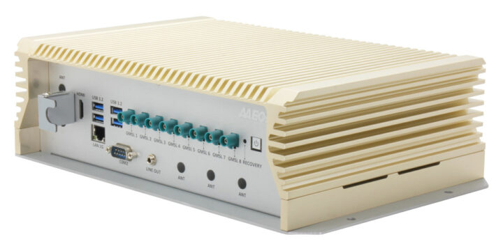
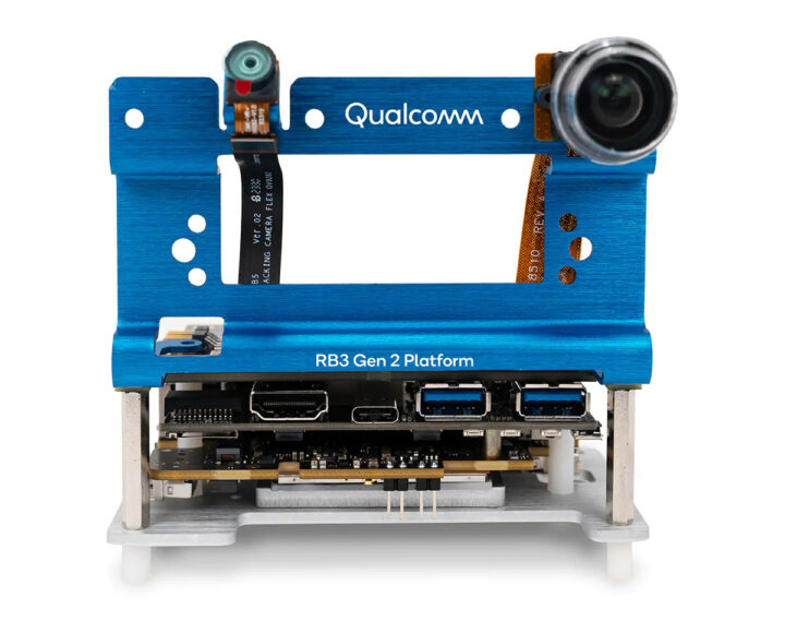
AAEON BOXER-8645AI is an embedded AI system powered by NVIDIA Jetson AGX Orin that features eight GMSL2 connectors working with e-con Systems’ NileCAM25 Full HD global shutter GMSL2 color cameras with up to 15-meter long cables.
The BOXER-8645AI is fitted with the Jetson AGX Orin 32GB with 32GB LPDDR5 and 64GB flash and up to 200 TOPS of AI performance. Other features include M.2 NVMe and 2.5-inch SATA storage, 10GbE and GbE networking ports, HDMI videos, and a few DB9 connectors for RS232, RS4
AAEON BOXER-8645AI is an embedded AI system powered by NVIDIA Jetson AGX Orin that features eight GMSL2 connectors working with e-con Systems’ NileCAM25 Full HD global shutter GMSL2 color cameras with up to 15-meter long cables.
The BOXER-8645AI is fitted with the Jetson AGX Orin 32GB with 32GB LPDDR5 and 64GB flash and up to 200 TOPS of AI performance. Other features include M.2 NVMe and 2.5-inch SATA storage, 10GbE and GbE networking ports, HDMI videos, and a few DB9 connectors for RS232, RS485, DIO, and CAN Bus interfaces. The embedded system takes 9V to 36V wide DC input from a 3-pin terminal block.
Camera interfaces – 8x GMSL2 (Gigabit Multimedia Serial Link 2) with FAKRA connectors compatible with NileCAM25 full HD global shutter camera with AR0234CS sensor, up to 15-meter cable
Networking
10GbE RJ45 LAN port
Gigabit Ethernet RJ45 LAN port
Up to 8x additional LAN ports (upon request)
Optional WiFi and Bluetooth via M.2 socket (see Expansion section)
Optional 4G LTE via M.2 socket (see Expansion section) and 2x SIM card slots
Optional GNSS support (I’d assume through the 4G LTE module?)
7x antenna holes
USB
4x USB 3.2 Gen 2 Type-A ports
1x Micro USB for flashing the OS
Serial
2x Isolated CAN Bus via DB-9 connector
2x RS-232/RS-485 via DB-9 connectors
8x DIO via DB-9 connector
Expansion
M.2 2230 E-Key socket for WiFi/BT
M.2 3052 B-Key socket for 4G LTE
M.2 2280 M-Key socket for NVMe SSD
Security – TPM support
Misc
9-axis IMU sensor support
Power and Recovery buttons
Power LED
Power Supply
9V to 36V wide DC input via 3-pin Terminal Block
Switch for Ignition Delay On/Off
Dimensions – 286 x 202 x 90mm)
Weight – 5 kg
Temperature Range – Operating: -25°C to 65°C with 0.5 m/s airflow; storage: -40°C to 85°C
Humidity – 5 ~ 95% @ 40°C, non-condensing
Anti-vibration – MIL-STD-810G, 514.6C Procedure 1, Category 4 Trucker/Semitrailer on US highway (Figure 514.6C-1-Category 4-Common carrier)
Anti-Shock – MIL-STD-810G, Method 516.6, Procedure I, flight vehicle equipment
Certifications – E-Mark, CE/FCC Class A
AAEON says the BOXER-8645AI runs Ubuntu Linux as part of the NVIDIA Jetpack 5.0 or above like every other Jetson Orin system on the market. GMSL2 cameras are used when high data transfer speed and low latency are required at distances up to 15m. In theory, it’s possible to extend MIPI CSI through kits such as the THine camera extension kit using Cat 5a “Ethernet” cables, but GSML2 cameras and FAKRA connectors make that more convenient with a single cable per camera.
We previously covered an NVIDIA Jetson Xavier AGX kit taking up to six GSML2 cameras from e-con Systems, but the BOXER-8645AI builds on that with a more powered Jetson AGX Orin model and up to eight GMSL2 cameras. The long cables and global shutter cameras (ideal for images with motion) make the solution especially useful for robotics (AMR) and automotive applications.
Jetson AGX Orin platform with 8 GMSL2 cameras – Not the BOXER system we are covering here but the NileCAM25_CUOAGX evaluation kit from e-con Systems
While AAEON and e-con Systems collaborated on the project, the BOXER-8645AI and NileCAM24 are sold separately for respectively $3,500 on AAEON eShop and $299 with a 15-meter cable on e-con Systems’ website. That means a complete system with eight cameras would cost close to $6,000. If you want to evaluate the solution first, it’s cheaper to get started with a development kit from e-con Systems ($499 with one camera, but no AGX Orin module) instead, then use the BOXER-8645AI for deployments.
Some mini PCs and firewall/network appliances are starting to show up with the Intel Processor U300/U300E penta-core CPU on Aliexpress and Amazon. It looks to be a 15W entry-level part for the 13th Gen Raptor Lake processor that may provide a more powerful and slightly more expensive alternative to the popular Alder Lake-N Processor and Core i3-N305 SoCs.
The Processor U300 offers one Performance core clocked at 1.10 GHz to 4.30 GHz (Turbo) and four Efficiency cores clocked at up to 3.20 GHz, wi
Some mini PCs and firewall/network appliances are starting to show up with the Intel Processor U300/U300E penta-core CPU on Aliexpressand Amazon. It looks to be a 15W entry-level part for the 13th Gen Raptor Lake processor that may provide a more powerful and slightly more expensive alternative to the popular Alder Lake-N Processor and Core i3-N305 SoCs.
The Processor U300 offers one Performance core clocked at 1.10 GHz to 4.30 GHz (Turbo) and four Efficiency cores clocked at up to 3.20 GHz, with the embedded part (U300E) handling slightly lower max frequencies for a wider operating temperature range. As usual, the Performance core supports multi-threading, so the Processor U300 supports six threads. Intel Ark shows it can support up to 96GB DDR5-5200 RAM, embeds a 48EU Intel UHD Graphics capable of driving up to four independent displays, and offers 20 lanes of PCIe Gen4 (vs 9-lane for Alder Lake-N), as well as Thunderbolt 4 support.
Let’s have a look at the specifications on the HUNSN BJ03 mini PC from the Amazon link to better understand its benefits:
SoC – Intel Processor U300
Penta-core/6-thread Raptor Lake CPU with one P-core @ 1.10 GHz / 4.40 GHz (Turbo) and four E-cores up to 3.3 GHz with 8MB Cache
GPU – 48EU Intel UHD Graphics up to 1.10 GHz
Package – FCBGA1744 (50x25mm)
Processor Base Power: 15 W; Maximum Turbo Power: 55 W: Minimum Assured Power: 12 W
System Memory – Up to 64GB (not 96GB?) dual-channel DDR5-5200 via 2x SODIMM slot
Storage – M.2 PCIe 4.0 x4 socket for NVMe SSD
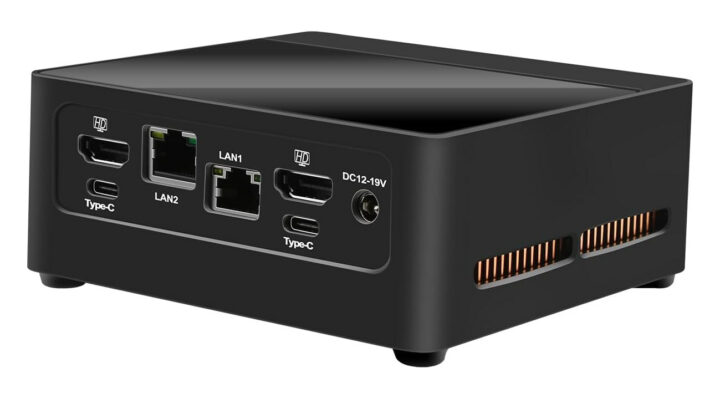
Video Output
2x HDMI 2.0 ports
2x DisplayPort via USB-C up to 7680×4320 @ 60 Hz
Four independent displays support
Audio – 3.5mm (stereo output+mic) headphone jack
Networking
2.5GbE RJ45 port via Intel i226-V controller
Optional WiFi 6 and Bluetooth 5.2 via M.2 wireless module
USB
2x USB 2.0 Type-A ports
2x USB 3.2 Type-A ports
2x USB 3.2 Gen 2 Type-C ports
Security – TPM 2.0
Misc
Power button
RST pinhole
“Smart silent fan”
Power Supply – 12V to 19V via DC jack (12V/5A PSU provided)
Dimensions – 120 x 112 x 47mm
Weight – 600 grams
Temperature Range – Operating: -20°C to 60°C; storage: -40°C~85°C
Relative Humidity – 5% to 90% non-condensing
The HUNSN BJ03 mini PC ships with a 60W power supply, a power cord, a VESA mount, and a warranty card. The system ships with Windows 11 Pro by default, but the company says Windows 10, Ubuntu, and other Linux distributions are also supported. You can apparently leave a message to let HUNSN install the OS of your choice…
The good thing about the specifications for the BJ03 is that it uses the quad-display output capabilities of the Processor U300 SoC, and offers dual-channel DDR5 which should especially help with 3D graphics performance along with the more powerful iGPU. What’s a bit disappointing is the lack of a Thunderbolt 4 / USB4 port as the Raptor Lake processor should support it according to Intel Ark.
Network appliance based on Intel Processor U300
The price/performance ratio is probably not quite as good as the Alder Lake-N models, as the HUNSN BJ03 sells for $473.30 on Amazon with 16GB DDR5 and a 256GB SSD, and I was unable to locate that specific model on Aliexpress. For reference, an Intel Processor U300E-based 2-in-1 mini PC and network appliance with eight 2.5GbE ports starts at $428.99 (barebone) on Aliexpress, but you can lower the price with coupon USAFF50 (US only) as Aliexpress has a promotion for orders over $369. As a side note, the Intel Processor U300E is also an option in the AAEON COM-RAPC6 COM Express module we covered last month, and the U300/U300E processors were launched in Q1 2023, at the same time as most Alder Lake-N processors, but never quite got the same level of adoption or press coverage…
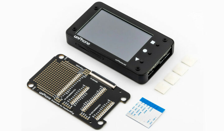
Pimoroni, in partnership with the University of Sheffield, introduced the unPhone – an open-source non-cellular IoT development platform built around the ESP32-S3 wireless microcontroller. The unPhone isn’t meant to replace phones but can simplify tasks and give you more control over your data.
In addition to the ESP32-S3, it features a 3.5″ 320×480 touchscreen display, LoRaWAN, Wi-Fi, Bluetooth, a vibration motor, an accelerometer, and various other features. Designed with these capabilities, t
Pimoroni, in partnership with the University of Sheffield, introduced the unPhone – an open-source non-cellular IoT development platform built around the ESP32-S3 wireless microcontroller. The unPhone isn’t meant to replace phones but can simplify tasks and give you more control over your data.
In addition to the ESP32-S3, it features a 3.5″ 320×480 touchscreen display, LoRaWAN, Wi-Fi, Bluetooth, a vibration motor, an accelerometer, and various other features. Designed with these capabilities, this module can be used for teaching and rapid prototyping, while also finding applications in aquaponics.
unPhone key features and components
Wireless module – ESP32-S3-WROOM-1U-N8
MCU – ESP32-S3 dual-core Tensilica LX7 up to 240 MHz with 512KB SRAM and 8MB PSRAM
Storage – 8MB Quad SPI flash
Wireless – 2.4 GHz WiFi 4 and Bluetooth LE 5
Hardware Features
LCD touchscreen for debugging and UI creation.
LoRaWAN for free radio communication
Vibration motor for notifications.
IR LEDs for remote control.
Accelerometer for motion sensing.
SD card reader for data storage.
Power and reset buttons.
1.2Ah LiPo battery management and USB-C charging.
Expansion Options
Expansion board with three Featherwing slots
Supported by 3D print housings with freely available designs.
Dimension – Not Available
The project is completely open-source, with all files including schematics, board, firmware, and more available on their GitLab repository. To simplify the development process, Professor Hamish Cunningham of the University of Sheffield has created an open-license 300-page textbook covering the hardware and making it easier for developers to get started.
unPhone’s internals with battery, ESP32-S3, and LoRa module
The unPhone is also software-friendly and supports popular development environments such as Arduino IDE, PlatformIO, and Espressif’s IDF framework. It also allows programming in both C++ and CircuitPython, for added simplicity. Additionally, LVGL graphics support and broad compatibility with Raspberry Pi extension modules make it easy to integrate into a wide range of projects.
The unPhone can be found in Pimoroni’s official shop and it is priced at £139.50 around $173.25, but at the time of writing it’s out of stock. For more details, you can check out unphone.net.
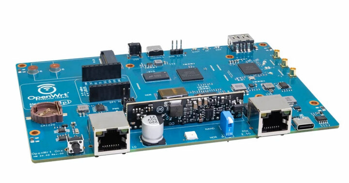
John Crispin has recently received the first samples of the “OpenWrt One/AP-24.XY” Filogic 820-based WiFi 6 router board, manufactured by Banana Pi. Those will be officially supported by OpenWrt developers with assistance from MediaTek.
Announced in January 2024, we only had the specifications of the OpenWrt One router so far, but since the first samples are now available we have more details including several photos of the board, and some units will be auctioned away at the OpenWrt Summit taken
John Crispin has recently received the first samples of the “OpenWrt One/AP-24.XY” Filogic 820-based WiFi 6 router board, manufactured by Banana Pi. Those will be officially supported by OpenWrt developers with assistance from MediaTek.
Announced in January 2024, we only had the specifications of the OpenWrt One router so far, but since the first samples are now available we have more details including several photos of the board, and some units will be auctioned away at the OpenWrt Summit taken place in Cyprus on May 18-19.
John explains fifteen prototypes will be manufactured, a website will be set up (maybe openwrt dot one), and that MediaTek helped with documentation:
Just dropping a quick update on the OpenWrt One project. I’ve received the first batch of three PCBs for testing today. I am in the process of testing the hardware to make sure everything works as intended. There are twelve further early prototype boards on standby in case we need to tweak anything hardware-wise…
Work is underway to establish a website where all legal information and links to our sources will be provided. Keeping everything transparent and accessible is crucial for us. MediaTek also generously released a substantial amount of programming manuals for the SoC used by the OpenWrt One which will be made available shortly.
Here’s a reminder of the OpenWrt One router specifications:
USB Type-C (device, console) port using Holtek HT42B534-2 UART to USB chip
Expansion – MikroBUS socket for expansion modules
Debugging – Console via USB-C port or 3-pin header, 10-pin JTAG/SWD header for main SoC
Misc
Reset and User buttons
Boot select switch: NAND (regular) or NOR (recovery)
2x PWM LEDs, 2x Ethernet LED (GPIO driven)
EM6324 External hardware watchdog
NXP PCF8563TS (I2C) RTC with battery backup holder for CR1220 coin-cell
Power Supply
12V USB-PD on USB-C port (might have changed to up to 15V)
Optional 802.3at/af PoE via RT5040 module
Dimensions – 148 x 100.5 mm compatible with Banana Pi BPI-R4 case design
Certifications – FCC/EC/RoHS compliance
There’s still no information about mass production and general availability, but at least one or two samples will be given away during the OpenWrt Summit according to a discussion thread started by Arınç ÜNAL on April 10. John further added that the 15 EVT samples mentioned have already been tested, and a new production run of 100 DVT samples would start shortly. These 100 samples will have OpenWrt OUI macs and calibration data, and the winners of the auction will receive samples via express courier (as opposed to being given at the OpenWrt Summit).
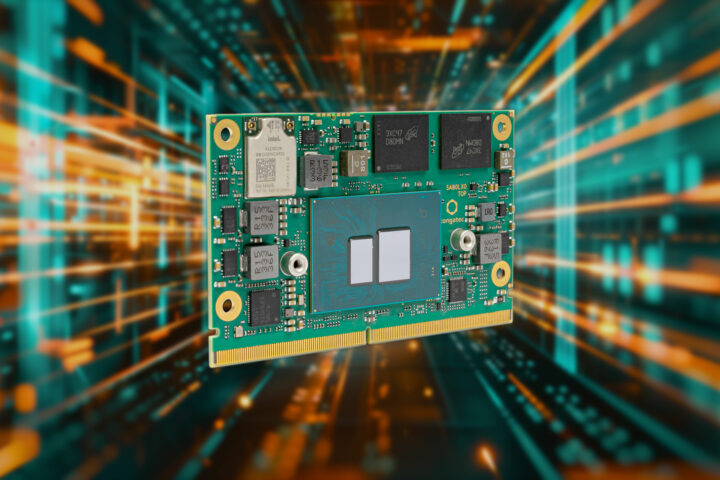
Congatec’s new conga-SA8 SMARC modules are powered by the Intel Atom x7000RE “Amston Lake” processors. With twice the processing cores and similar power consumption to the previous generation, congatec’s new credit-card-sized modules are “intended for future-facing industrial edge computing and powerful virtualization.”
An Intel Core i3‑N305 Alder Lake-N processor is also offered as an alternative to the Intel Atom x7000RE series for high-performance IoT edge applications. The conga-SA8 modules
Congatec’s new conga-SA8 SMARC modules are powered by the Intel Atom x7000RE “Amston Lake” processors. With twice the processing cores and similar power consumption to the previous generation, congatec’s new credit-card-sized modules are “intended for future-facing industrial edge computing and powerful virtualization.”
An Intel Core i3‑N305 Alder Lake-N processor is also offered as an alternative to the Intel Atom x7000RE series for high-performance IoT edge applications. The conga-SA8 modules support up to 16GB LPDDR5 onboard memory, 256GB eMMC 5.1 onboard flash memory, and offer several high-bandwidth interfaces such as USB 3.2 Gen 2, PCIe Gen 3, and SATA Gen 3. The integrated Intel UHD Gen 12 graphics processing unit has up to 32 execution units and can power three independent 4K displays.
The conga-SA8 is described as virtualization-ready and has a hypervisor (virtual machine monitor) integrated into the firmware. The RTS hypervisor takes complete advantage of the eight processing cores supported by the SA8 module and can enable the development of consolidated systems for multiple applications without introducing extra costs.
Intel Atom x7425E Amston Lake (4-core processor with 1.5GHz core frequency up to 3.4GHz (Turbo)
Intel Atom x7433RE Amston Lake (4 x 1.5 GHz, 9W)
Intel Atom x7835RE Amston Lake (8 x 1.3 GHz, 12W)
All with integrated Intel UHD Graphics with up to 32EUs
Memory – 16GB max. onboard LPDDR5 (up to 4.800 MT/s)
Storage
eMMC 5.1 onboard flash up to 256 GB (optional)
SATA Gen 3.2
NVMe SSD via 4x PCIe Gen3
Video
Dual channel LVDS transmitter (support for flat panels with 2 x 24 bit data mapping up to a resolution of 1920×1200 @60Hz) | shared with eDP(option) or MIPI-DSI 1.3 x4 (option)
HDMI 2.0b: 4K x 2K @ 60Hz
eDP 1.4b: 4096 x 2304 @ 60Hz HBR3
DP 1.4: 4096 x 2304 @ 60Hz
3 independent display pipes, up to 3x 4Kp60 resolution
Ethernet – 2x 2.5 GbE with TSN support via Intel i226 Ethernet controller series, Supporting Time Sensitive Networking (TSN), 2 Software Definable Pins (SDPs) to be used for IEEE 1588
Wireless – Intel Wi-Fi 6E AX210, BT 5.3 (optional)
USB – 2x USB 3.2 Gen 2, 6x USB 2.0
Other Peripherals
I2C – 3x I²C bus, 2 x I²C CSI, GP I²C
SPI, eSPI, 4x UART, SM-Bus
12x GPIOs
Power Management – ACPI 5 .0 compliant, Smart Battery Management
congatec Board Controller – Multistage watchdog, non-volatile user data storage, manufacturing and board information, board statistics, fast mode and multi-master I²C bus, power loss control
Dimensions – 82 x 50 mm (SMARC 2.1 form factor)
Temperature Range
Embedded SKUs: Operating 0°C to 60°C | Storage -20°C to 80°C
Industrial SKUs: Operating -40°C to 85°C | Storage -40°C to 85°C
Humidity
Operating: 10 to 90% r. H. non-condensing
Storage 5 to 95% r. H. non-condensing
Operating Systems – Windows 11, Windows 11 IoT Enterprise, Windows 10, Windows 10 IoT Enterprise, Linux
Certain variants of the conga-SA8 SMARC modules are designed for industrial environments, with an operating temperature range of -40°C to 85°C. The modules also feature in-band error correction code (ECC) and soldered DRAM for increased resilience in harsh environments.
Expected applications include stationary and mobile control systems for manufacturing and logistics, including AMRs (Autonomous Mobile Robots), AGVs (Automated Guided Vehicles), and medical technology. Other application areas are rail, transportation, construction, agriculture, and forestry.
The conga-SA8 SMARC module also comes in congatec’s application-ready computer-on-module format, aReady.COM. They offer configurations that include a pre-installed ctrlX OS (an industrial Linux operating system from Bosch Rexroth) and virtual machines for real-time control, HMI, AI, IIoT data exchange, and other tasks. Furthermore, congatec’s design-in services, evaluation boards, documentation, and training aim to simplify application development and reduce time to market.
The press release and product page contain more information about the modules. You can get a price quote by requesting it on the product page.
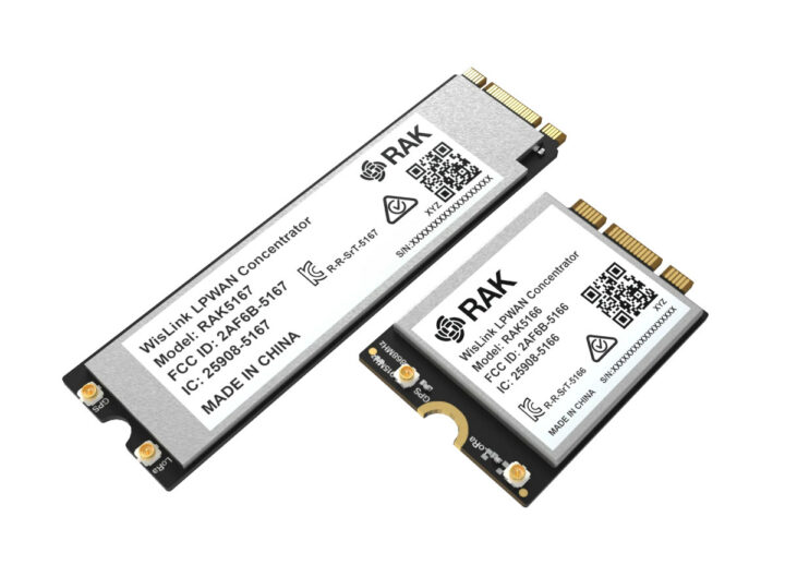
RAKwireless has recently introduced two new LoRaWAN products with the RAK5166/67 WisLink M.2 3042/2280 concentrator module based on the Semtech SX1303 RF transceiver and the RAK7285 WisGate Edge Ultra Full-Duplex gateway for high-density network deployments, particularly for smart city infrastructure, metering applications, and other scenarios requiring reliable two-way communication at scale.
RAK5166 and RAK5167 M.2 3042 and 2280 LoRaWAN concentrator modules
RAK5167 (left) and RAK5166 (right)
R
RAKwireless has recently introduced two new LoRaWAN products with the RAK5166/67 WisLink M.2 3042/2280 concentrator module based on the Semtech SX1303 RF transceiver and the RAK7285 WisGate Edge Ultra Full-Duplex gateway for high-density network deployments, particularly for smart city infrastructure, metering applications, and other scenarios requiring reliable two-way communication at scale.
RAK5166 and RAK5167 M.2 3042 and 2280 LoRaWAN concentrator modules
RAK5167 (left) and RAK5166 (right)
RAK5166/RAK5167 specifications:
Wireless
Semtech SX1303 baseband processor with 8 x 8 channels LoRa packet detectors, 8x SF5-SF12 LoRa demodulators, 8x SF5-SF10 LoRa demodulators, one 125/250/500 kHz high-speed LoRa demodulator, and one (G)FSK demodulator
Tx power up to 27 dBm
Rx sensitivity down to -139 dBm @ SF12, BW 125 kHz
Supports global license-free frequency band (EU868, IN865, RU864, US915, AU915, KR920, AS923-1, AS923-2, AS923-3, AS923-4)
Listen Before Talk (LBT) support
Fine Timestamp
Built-in ZOE-M8Q GPS module (optional)
2x MHF4 IPEX connectors for the LoRa and GNSS (optional) antennas
Host interface – PCI Express M.2 Key B-M connector; supports USB interface too
Dimensions – M.2 Type 3042/2280 form factor
RAK5166/RAK5167 block diagram
The RAK5166/RAK5167 M.2 modules have been engineered to work with industrial PCs and IoT gateways with M.2 slots for applications such as manufacturing, logistics, smart buildings, etc… It provides an alternative to the n-Fuse SX1303 mPCIe LoRaWAN concentrator card we covered a few years ago. Further technical information can be found on the documentation website, but I could see nothing about drivers/software.
RAKWireless RAK5166/RAK5167 M.2 LoRaWAN modules are sold for $89 or $99 depending on whether you need GPS, and ship with a LoRa antenna and a GPS antenna (if the GPS option is selected). You can also get an 8% discount with the coupon code XUO54T.
8 LoRa channels in Full-duplex (16 channels variant is coming soon)
30 dBm Max TX power
RX sensitivity down to -139 dBm
In-built cavity filters for out-of-band interference suspension
In-built lightning protection of the antenna ports
External LoRa antenna
Dying Gasp
LBT (Listen Before Talk)
Supported regions – US915 and AU915
Cellular (RK7285C model) – EG95-NA for North America or EG25-AU for Latin America, Australia, and New Zealand
GNSS – GPS with External antenna (Fine timestamp support)
Antennas
LoRa – N-Type connector (one for the 8-channel gateway and two for the 16-channel gateway)
GPS – 1x N-Type connector
Wi-Fi – 2x N-Type connectors
LTE – 2x N-Type connectors (only for RAK7285C)
Wired networking – 10/100M Ethernet RJ45 port
Power Supply
42 to 57V DC via PoE (802.3at) + Surge protection
Supports 9V-36V DC power or Battery Plus Solar system
Dimensions – 310 x 290 x 146 mm (Aluminum enclosure)
Installation Method – Pole or wall mounting
Temperature Range – -30°C to +55°C
IP Rating – IP67 industrial-grade enclosure with gable glands
The gateway runs WisGateOS 2 and supports a range of software features including remote management with WisDM Fleet Management, OpenVPN and Wireguard extension add-ons, a built-in Network Server, LoRaWAN 1.0.3 (LoRaWAN 1.0.4 for the Built-in server is coming soon), Basics Station and Packet forwarder, LoRaFrame filtering (node whitelisting), MQTT v3.1 Bridging with TLS encryption (compatible with ChirpStack LNS), Buffering of LoRa frames in Packet Forwarder mode in case of NS outage (no data loss), Listen Before Talk, and Fine timestamping.
As you’ll have noticed from the specifications, the gateway is only available in the 915 MHz bands, and not the 868 MHz bands so users from Europe, Southeast Asia, and other locales relying on the latter are out of luck for now. You’ll find hardware and software documentation on RAKwireless website that notablt explains how to use the full-duplex gateway with AWS IoT Core, The Things Network (TTN), ChirpStack, and Actility ThingPark.
The RAK7285 WisGate Edge Ultra Full-Duplex gateway ships with a power cable, a PoE injector, a GPS antenna, two 2.4GHz antennas, two 4G LTE antennas (for RAK7285C), a mounting bracket, an installation bracket, and a set of screws. It can be purchased for $769 to $859 depending on whether cellular connectivity is needed. Somehow, the LoRa antennas are not included and must be purchased separately… The XUO54T coupon code also works here and for anything ordered on the RAKwireless store.
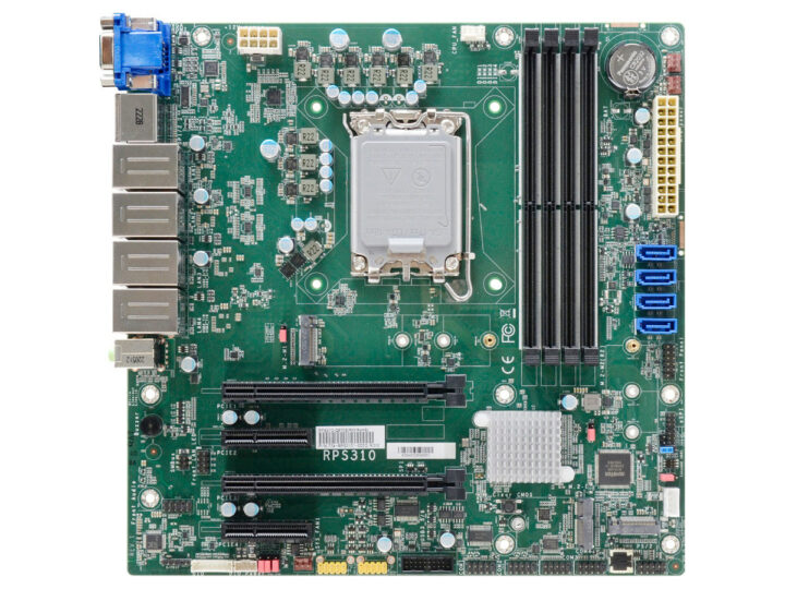
DFI has recently unveiled two new Industrial MicroATX Motherboards, the RPS310 and ADS310, that claim to have support for Core 12th Gen (Alder Lake-S), 13th Gen (Raptor Lake-S), and 14th Gen (Raptor Lake-S Refresh) processors. The motherboards can be built around R680E or Q670E chipset and support a range of peripherals including VGA, DP++, HDMI, PCIe, M.2 M key, SATA3.0, and much more.
The key difference between the two is that the RPS310 supports DDR5 memory, features 4x Intel 2.5GbE network c
DFI has recently unveiled two new Industrial MicroATX Motherboards, the RPS310 and ADS310, that claim to have support for Core 12th Gen (Alder Lake-S), 13th Gen (Raptor Lake-S), and 14th Gen (Raptor Lake-S Refresh) processors. The motherboards can be built around R680E or Q670E chipset and support a range of peripherals including VGA, DP++, HDMI, PCIe, M.2 M key, SATA3.0, and much more.
The key difference between the two is that the RPS310 supports DDR5 memory, features 4x Intel 2.5GbE network connections, and has a 10-year CPU lifecycle with optional 5-year extended support. In contrast, the ADS310 supports DDR4 memory, features 2x Intel 10GbE + 2x Intel 2.5GbE network connections, and boasts a longer 15-year CPU lifecycle support.
We’ve previously covered motherboards with a similar form factor, including the HiFive Pro P550 and Milk-V Pioneer, both powered by RISC-V CPUs. If you’re interested in alternative architectures, you might also enjoy our article on the Edge Server SynQuacer E-Series, a 24-core Arm-based PC.
2 x M.2 2242/2260/2280 M key (PCIe x4 Gen4 NVMe/SATA support)
BIOS – AMI SPI 256Mbit
Chipset – Intel R680E/Q670E Chipset
Backplane I/O
Ethernet – 2 x 2.5GbE (1 x Intel I226-LM & 1 x Intel I226-V) or 4 x 2.5GbE I226-V (R680E only)
USB – 4 x USB 3.2 Gen 2, 4 x USB 3.2 Gen 1
Display – 2 x DP++, 1 x HDMI 2.0a, 1 x VGA
Sound – 1 x Line-out, 1 x Mic-in, 1 x Line-in with Realtek ALC888 Audio codec
Internal I/O
USB – 2 x USB 3.2 Gen1, 4 x USB 2.0
Sound – 1 x Front Audio Header, 1 x S/PDIF
SATA – 4 x SATA 3.0 (up to 6Gb/s)
RAID – 0/1/5/10
DIO – 4-IN / 8-OUT DIO
SMBus – 1 x SMBus
PS/2 – 1 x PS/2
Monitor Timer – Programmable System Reset from 1 to 255 Seconds
Safety Features – Trust platform module: Nuvoton TPM 2.0
Power Supply -ATX type with 8-pin ATX 12V and 24-pin ATX power connectors
Safety Certification – CE, FCC Class B, RoHS
Environmental Indicators
Operating Temperature: -5 to 65°C
Storage Temperature: -30 to 60°C (with RTC Battery), -40 to 85°C (without RTC Battery)
Operating/Storage Humidity: 5 to 95% RH
Mechanical Structure – microATX Form Factor: 244mm x 244mm with a PCB height of 1.6mm
The specifications provided above are for the RPS310 board, which shares almost identical specs with ADS310. The primary differences lie in memory and Ethernet support, as mentioned earlier. However, there are additional specifications to consider.
For PCIe support, RPS310 features 1 x PCIe x16 (Gen 5), 2 x PCIe x4 (Gen 4), and 1 x PCIe x4 (Gen 3, with x4 speed on R680E and limited to x1 speed on Q670E). On the other hand, ADS310 offers 2 x PCIe x16 (Gen 4) and 2 x PCIe x4 (Gen 4). Regarding USB ports, RPS310 provides 2 x USB 3.2 Gen 1 headers, whereas ADS310 offers 2 x USB 3.2 Gen 2 ports. Additionally, RPS310 includes 4-in / 8-out DIO functionality, while ADS310 features a more basic 8-bit DIO setup. For simplicity, I have made a table to compare both motherboards.
Product
RPS310-R680E/Q670E
ADS310-R680E/Q670E
System
Processor
14th Generation Intel® LGA 1700 Socket Processors, TDP support up to 125W Intel® Core I9-14900 (24 Cores, 36M Cache, up to 2.0 GHz); 65W Intel® Core I9-14900T (24 Cores, 36M Cache, up to 1.1 GHz); 35W Intel® Core I7-14700 (20 Cores, 33M Cache, up to 2.1 GHz); 65W Intel® Core I7-14700T (20 Cores, 33M Cache, up to 1.3 GHz); 35W Intel® Core I5-14500 (14 Cores, 24M Cache, up to 2.6 GHz); 65W Intel® Core I5-14500T (14 Cores, 24M Cache, up to 1.7 GHz); 35W Intel® Core I3-14100 (4 Cores, 12M Cache, up to 3.5 GHz); 60W Intel® Core I3-14100T (4 Cores, 12M Cache, up to 2.7 GHz); 35W Intel® 300T (2 Cores, 6M Cache, up to 3.4 GHz); 35W
13th Generation Intel® LGA 1700 Socket Processors, TDP support up to 125W Intel® Core I9-13900E (24 Cores, 36M Cache, up to 5.2 GHz); 65W Intel® Core I9-13900TE (24 Cores, 36M Cache, up to 5.0 GHz); 35W Intel® Core I7-13700E (16 Cores, 30M Cache, up to 5.1 GHz); 65W Intel® Core I7-13700TE (16 Cores, 30M Cache, up to 4.8 GHz); 35W Intel® Core I7-13700T (16 Cores, 30M Cache, up to 4.9 GHz); 35W Intel® Core I5-13500E (14 Cores, 24M Cache, up to 4.6 GHz); 65W Intel® Core I5-13500TE (14 Cores, 24M Cache, up to 4.5 GHz); 35W Intel® Core I5-13500T (14 Cores, 24M Cache, up to 4.6 GHz); 35W Intel® Core I5-13400E (10 Cores, 20M Cache, up to 4.6 GHz); 65W Intel® Core I3-13100E (4 Cores, 12M Cache, up to 4.4 GHz); 65W Intel® Core I3-13100TE (4 Cores, 12M Cache, up to 4.1 GHz); 35W Intel® Core I3-13100T (4 Cores, 12M Cache, up to 4.2 GHz); 35W
12th Generation Intel® LGA 1700 Socket Processors, TDP support up to 125W Intel® Core i9-12900E (16 Cores, 30M Cache, up to 5.0 GHz); 65W Intel® Core i9-12900TE (16 Cores, 30M Cache, up to 4.8 GHz); 35W Intel® Core i7-12700E (12 Cores, 25M Cache, up to 4.8 GHz); 65W Intel® Core i7-12700TE (12 Cores, 25M Cache, up to 4.6 GHz); 35W Intel® Core i5-12500E (6 Cores, 18M Cache, up to 4.5 GHz); 65W Intel® Core i5-12500TE (6 Cores, 18M Cache, up to 4.3 GHz); 35W Intel® Core i3-12100E (4 Cores, 12M Cache, up to 4.2 GHz); 60W Intel® Core i3-12100TE (4 Cores, 12M Cache, up to 4.0 GHz); 35W Intel® Pentium® G7400E (2 Cores, 6M Cache, 3.6 GHz); 46W Intel® Pentium® G7400TE (2 Cores, 6M Cache, 3.0 GHz); 35W Intel® Celeron® G6900E (2 Cores, 4M Cache, 3.0 GHz); 46W Intel® Celeron® G6900TE (2 Cores, 4M Cache, 2.4 GHz); 35W
Wafer set
Intel® R680E/Q670E Chipset
Intel® R680E/Q670E Chipset
Memory
Four 288-pin UDIMM up to 128GB (ECC/Non-ECC) Dual Channel DDR5 up to 4400 MHz *only R680E support ECC memory *Speed support list follow User’s Manual
Four 288-pin DIMM up to 128GB Dual Channel DDR4 3200 MHz (ECC support: R680E only)
1 x VGA 2 x DP++ 1 x HDMI 2.0a VGA: resolution up to 1920x1200 @ 60Hz DP++: resolution up to 4096x2304 @ 60Hz HDMI: resolution up to 4096x2160 @ 24Hz
1 x VGA, resolution up to 1920x1200 @ 60Hz 2 x DP++, resolution up to 4096×2304 @ 60Hz 1 x HDMI 2.0a, resolution up to 4096x2160 @ 24Hz
Quadruple display
VGA + 2 DP++ + HDMI
VGA + 2 DP++ + HDMI
Expansion
Interface
2 x PCIe x16 (Gen 4) (1 x16 signals or 2 x8 signals) 2 x PCIe x4 (Gen 4) 1 x M.2 2230 E key (opt. PCIe/USB 2.0/Intel CNVi support) (Discrete Wifi 6E support) 1 x M.2 2242/2260/2280 M key (PCIe x4 Gen4 NVMe/SATA support) 1 x M.2 2242/2260/2280 M key (PCIe x4 Gen4 NVMe support)
1 x PCIe x16 (Gen 5) 2 x PCIe x4 (Gen 4) 1 x PCIe x4 (Gen 3) (R680E: x4 signal; Q670E: x1 signal)
1 x M.2 2242/2260/2280 M key (PCIe x4 Gen4 NVMe) 1 x M.2 2242/2260/2280 M key (PCIe x4 Gen4 NVMe/SATA) 1 x M.2 2230 E key (PCIe/USB 2.0/Intel CNVi support) (Discrete Wifi 6E support)
Audio
Audio codec
Realtek ALC888
Realtek ALC888
Ethernet
Controller
1 x Intel® I226-LM (Core i9/i7/i5 support iAMT) 1 x Intel® I226-V 2 x Intel® I226-V (only R680E support)
1 x Intel® I226-LM PCIe (10M/100M/1000Mbps/2.5G) (only Xeon, Core i9/i7/i5 support iAMT) 1 x Intel® I226-V PCIe (10M/100M/1000Mbps/2.5G) 2 x Intel® x550-AT2 (10 GBASE-T/1 GbE/100 Mbps) (no support WOL)
Backplane input/output
Ethernet
2 x 2.5GbE (RJ-45) or 4 x 2.5GbE (RJ-45) (only R680E support)
2 x 2.5GbE 2 x 10GbE
USB
4 x USB 3.2 Gen 2 4 x USB 3.2 Gen 1
4 x USB 3.2 Gen 2 4 x USB 3.2 Gen 1
Display
2 x DP++ 1 x HDMI 2.0a 1 x VGA
1 x VGA 2 x DP++ 1 x HDMI 2.0a
Sound source
1 x Line-out 1 x Mic-in 1 x Line-in (opt. by request, MOQ required)
1 x Line-out 1 x Mic-in 1 x Line-in (opt. by request, MOQ required)
Internal input/output
String
2 x RS-232/422/485 (RS-232 w/ power) (2.54mm pitch) 2 x RS-232 (2.54mm pitch)
2 x RS-232/422/485 (RS-232 w/ power) (2.54mm pitch)
USB
2 x USB 3.2 Gen1 4 x USB 2.0 (2.54mm pitch) (1 x USB 2.0 colay vertical Type A)
2 x USB 3.2 Key B box header (R680E Gen2 ; Q670E Gen1) 4 x USB 2.0 (2.54mm pitch) (colay vertical Type A, MOQ required)
Sound source
1 x Front Audio Header 1 x S/PDIF
1 x Front Audio Header 1 x S/PDIF
SATA
4 x SATA 3.0 (up to 6Gb/s) RAID 0/1/5/10
4 x SATA 3.0 (up to 6Gb/s) RAID 0/1/5/10
DIO
4-IN / 8-OUT DIO
1 x 8-bit DIO
SMBus
1 x SMBus
1 x SMBus
PS/2
1 x PS/2 (2.54mm pitch)
1 x PS/2 (2.54mm pitch)
Monitor timer
Output and time interval
System Reset, Programmable via Software from 1 to 255 Seconds
System Reset, Programmable via Software from 1 to 255 Seconds
Safety
Trust platform module
Nuvoton TPM 2.0
Nuvoton TPM 2.0
Power supply
Type
ATX
ATX
Connecting port
8-pin ATX 12V power 24-pin ATX power
8-pin ATX 12V power 24-pin ATX power
Energy consumption
TBD
TBD
RTC battery
CR2032 Coin Cell
CR2032 Coin Cell
Support operation system
Microsoft
Windows 10 IoT Enterprise 64-bit Windows 11 Enterprise
Windows 10 IoT Enterprise 64-bit Windows 11 Enterprise
Linux
Linux
Linux
Environmental indicators
Temperature
Operating: -5 to 65°C Storage: -30 to 60°C with RTC Battery; -40 to 85°C without RTC Battery
Operating: -5°C ~ 65°C Storage: -30°C ~ 60°C with RTC Battery; -40°C ~ 85°C without RTC Battery
Humidity
Operating: 5 to 95% RH Storage: 5 to 95% RH
Operating: 5% ~ 95% RH Storage: 5% ~ 95% RH
MTBF
TBD
TBD
Mechanical structure
Dimensions
microATX Form Factor 244mm (9.6") x 244mm (9.6")
microATX Form Factor 244mm (9.6") x 244mm (9.6")
Height
PCB: 1.6mm Top Side: TBD Bottom Side: TBD
PCB: 1.6mm Top Side: TBD Bottom Side: TBD
Safety certification
Certification
CE, FCC Class B, RoHS
CE, FCC Class B, RoHS, UKCA
Packing list
Packing list
1 RPS310-R680E/Q670E motherboard 1 COM port cable (Length: 300mm, 2 x COM ports) A81-015026-023G 1 Serial ATA data cable (Length: 500mm) 332-553001-005G 1 I/O shield A49-RPS310-000G
1 ADS310-R680E/Q670E motherboard 1 COM port cable (Length: 300mm, 2 x COM ports) A81-015026-023G 1 Serial ATA data cable (Length: 500mm) 332-553001-005G 1 I/O shield -2LAN: A49-ADS630-010G -4LAN: A49-ADS630-000G
ADS310 Block Diagram and Interfaces DiagramRPS310 Block Diagram and Interfaces Diagram
The company provides block diagrams and interface diagrams for both boards, along with other documents such as the full specification guide and user manual, which are available on their respective product pages.
GEEKOM A7 is a powerful mini PC based on an AMD Ryzen 9 7940HS octa-core/16-thread processor that normally sells for $849 with 32GB RAM and a 2TB SSD. But you can get $200 off using cnxa7off coupon code to get the discount on GEEKOM US or GEEKOM UK bringing the price down to $649.
The mini PC also supports up to four 4K displays through HDMI 2.0 and USB-C ports, provides fast networking via a 2.5GbE jack and a WiFi 6E + Bluetooth 5.3 module, and offers plenty of USB ports for expansion in a comp
GEEKOM A7 is a powerful mini PC based on an AMD Ryzen 9 7940HS octa-core/16-thread processor that normally sells for $849 with 32GB RAM and a 2TB SSD. But you can get $200 off using cnxa7off coupon code to get the discount on GEEKOM US or GEEKOM UK bringing the price down to $649.
The mini PC also supports up to four 4K displays through HDMI 2.0 and USB-C ports, provides fast networking via a 2.5GbE jack and a WiFi 6E + Bluetooth 5.3 module, and offers plenty of USB ports for expansion in a compact form factor.
GEEKOM A7 specifications:
SoC – AMD Ryzen 9 7940HS 8-core/16-thread processor up to 4.0GHz with 16MB cache, AMD Radeon 780M Graphics; TDP: 35 to 54W
System Memory – 32GB dual-channel DDR5-5600 via 262-pin SODIMM sockets, upgradeable to 64GB
Storage
2TB NVMe PCIe x4 Gen 4 SSD
Full-size SD card reader
Video Output
2x HDMI 2.0 ports up to 4Kp60
2x USB-C ports with DisplayPort Alt. mode
Audio – 3.5mm audio jack, digital audio via HDMI ports
Connectivity
2.5GbE RJ45 port via a Realtek RTL8125BG-CG controller
WiFI 6E and Bluetooth 5.3
USB
3x USB 3.2 Gen 2 Type-A ports
1x USB 4 Gen3 Type-C port
1 x USB 3.2 Gen 2 Type-C port
1 x USB 2.0 Type-A port
Misc – Power button with LED, Kensington lock
Power Supply – 19V (120W) via DC jack
Dimensions – 112.4 x 112.4 x 37 mm
The mini PC comes preloaded with Windows 11 Pro. When we reviewed the GEEKOM A7 we were impressed by its performance since it was the fastest mini PC we had tested so far, and everything worked as expected with the fan staying relatively quiet. Users interested in running Linux on the device may check out our Ubuntu 22.04/24.04 review which shows the performance is excellent and everything works except for the MediaTek MT7922 wireless module (Azurewave AW-XB591NF) with fast but unstable/unreliable WiFi 6 in Ubuntu 22.04 (OK in Ubuntu 24.04 daily image). We never managed to make Bluetooth work in either Ubuntu version. So we can definitely recommend the GEEKOM A7 running Windows 11 Pro, but Linux users would have to consider their wireless connectivity needs.
The GEEKOM A7’s $200 discount coupon code cnxa7off is valid until May 5, 2024. Customers benefit from free local shipping from a US or UK warehouse, a 30-day return and refund period, and a 3-year warranty.
Hardkernel has just launched an upgrade to their ODROID-H3/H3+ Jasper Lake SBC, with the ODROID-H4, ODROID-H4+, and ODROID-H4 Ultra boards powered by Intel Processor N97 or Intel Core i3-N305 Alder Lake N-Series processors.
The ODROID-H4 family supports up to 48GB DDR5-4800 memory and NVMe SSD storage, comes with up to two 2.5GbE, four SATA III ports, three 4K capable video output ports (HDMI and DisplayPort), a range of USB ports, and a 24-pin GPIO header.
ODROID-H4 specifications compared to
The ODROID-H4 family supports up to 48GB DDR5-4800 memory and NVMe SSD storage, comes with up to two 2.5GbE, four SATA III ports, three 4K capable video output ports (HDMI and DisplayPort), a range of USB ports, and a 24-pin GPIO header.
ODROID-H4 specifications compared to previous generation ODROID-H2+ and ODROID-H3 boards.
ODROID H2+
ODROID H3
ODROID H3+
ODROID H4
ODROID H4+
ODROID H4 Ultra
CPU
Intel Celeron J4115 quad-core processor up to 2.5 GHz
Intel Celeron N5105 quad-core processor up to 2.9 GHz
Intel Pentium N6005 quad-core processor up to 3.3 GHz
Intel Processor N97 quad-core processor up to 3.6 GHz
Intel Processor N97 quad-core processor up to 3.6 GHz
Intel Core i3-N305 octa-core processor up to 3.8 GHz
AVX2 support
No
No
No
Yes
Yes
Yes
TDP
10W
10W
10W
12W
12W
15W
iGPU
12EU up to 750 MHz
24EU up to 800 MHz
32EU up to 900 MHz
24EU up to 1200 MHz
24EU up to 1200 MHz
32EU up to 1250 MHz
Max memory
32GB DDR4-2400
64GB DDR4-2933
64GB DDR4-2933
48GB DDR5-4800
48GB DDR5-4800
48GB DDR5-4800
M.2 PCIe socket (for SSD or quad 2.5GbE add-on)
PCIe Gen2 x4
PCIe Gen3 x4
PCIe Gen3 x4
PCIe Gen3 x4
PCIe Gen3 x4
PCIe Gen3 x4
SATA III
2
2
2
None
4
4
Video Outputs
HDMI and DisplayPort
HDMI and DisplayPort
HDMI and DisplayPort
HDMI and 2x DisplayPort
HDMI and 2x DisplayPort
HDMI and 2x DisplayPort
Audio
3.5mm audio output and input jacks, optical S/PDIF
3.5mm audio output and input jacks, optical S/PDIF
3.5mm audio output and input jacks, optical S/PDIF
3.5mm audio output and input jacks, optical S/PDIF
3.5mm audio output and input jacks, optical S/PDIF
3.5mm audio output and input jacks, optical S/PDIF
2.5GbE
2
2
2
1
2
2
USB
2x USB 2.0 + 2x USB 3.0
2x USB 2.0 + 2x USB 3.0
2x USB 2.0 + 2x USB 3.0
2x USB 2.0 + 2x USB 3.0
2x USB 2.0 + 2x USB 3.0
2x USB 2.0 + 2x USB 3.0
24-pin GPIO header
Yes
Yes
Yes
Yes
Yes
Yes
TPM 2.0
No
Yes
Yes
Yes
Yes
Yes
Dimensions
110x110mm
110x110mm
110x110mm
120x120mm
120x120mm
120x120mm
Price at launch
$119
$129
$165
$99
$139
$220
The new ODROID-H4 family should be slightly thinner thanks to single-channel DDR5 memory (vs dual-channel DDR4)ODROID-H4 block diagram
The GPIO header offers the following interfaces for all models except for the ODROID-H2+: 2x I2C, 3x USB 2.0, 1x UART, 1x HDMI-CEC, ext. power button. The H2+ header has similar interfaces, but only one USB 2.0 and two UART. Some may note the maximum RAM capacity numbers differ from the data on Intel Ark, but the latter is not usually correct, and Hardkernel have tested their board up to the reported capacities. Users can still use the quad 2.5GbE Net Card to create a system with six 2.5GbE ports.
Some new features not listed in the specifications include a dual BIOS (ODROID-H4+ and ODROID-H4 Ultra only) in case the BIOS is corrupted during an update (e.g. because of a power outage), new types of cases so that a cooling fan can be mounted inside the case, and mini ITX kit for use with standard PC cases.
ODROID-H4 mini-ITX kit
Hardkernel also shared several benchmarks (and lots of information) comparing the different ODROID-H models including the compression/decompression benchmarks (7-Zip, xz, bzip2…) shown below with or without the “Unlimited Performance” mode – shown as UP in the chart – where the CPU can run in Turbo Boost mode with no time limit. All tests were performed on Ubuntu 22.04.3/4 (Gnome).
Those interested in GPU performance may be interested in the video below showing some games in action.
The ODROID-H4, H4+, and H4 Ultra can be purchased now for respectively $99, $139, and $220 with shipping starting next week. That’s for the board only, and you’ll need to add a power supply, SATA cables, memory, storage, a slim cooling fan, and potentially one of the cases compatible with the ODROID-H4 board with up to four 3.5-inch SATA drives.
Hello, the device I am going to review is the MaUWB_DW3000 with STM32 AT Command. This is an Ultra-wideband (UWB) module from MakerFabs. The core UWB module on this board is the DW3000 UWB transceiver, and it is also equipped with an ESP32 microcontroller programmable with the Arduino IDE, as well as OLED display. The manufacturer claims that this UWB board resolves multiple anchors and tags mutual conflicts and supports up to 8 anchors and 64 tags. Additionally, the manufacturer has added an ST
Hello, the device I am going to review is the MaUWB_DW3000 with STM32 AT Command. This is an Ultra-wideband (UWB) module from MakerFabs. The core UWB module on this board is the DW3000 UWB transceiver, and it is also equipped with an ESP32 microcontroller programmable with the Arduino IDE, as well as OLED display. The manufacturer claims that this UWB board resolves multiple anchors and tags mutual conflicts and supports up to 8 anchors and 64 tags. Additionally, the manufacturer has added an STM32 microcontroller to handle UWB multiplexing, allowing users to control the core UWB module by simply sending AT commands from an ESP32 microcontroller to the STM32 microcontroller. More information about this UWB board can be found on the manufacturer’s website.
“MaUWB_DW3000 with STM32 AT Command” unboxing
MakerFabs sent the package to me from China. Inside the package, there were 4 sets of the MaUWB_DW3000 with STM32 AT Command. Each set contains the module, a 3.7V 600mAh battery, and 2 pieces of 2.54mm 12-pin male pin headers. Additionally, there were 4 extra batteries and an ST-LINK V2 for uploading firmware to the STM32 microcontroller.
The received components.The components within a sealed package.The top side of the PCB.The bottom side of the PCB.
The main PCB has a red solder mask. On the top side, the primary components include the ESP32-WROVER-B module and a 128×64 OLED display. Near the USB Type-C connector, there are RST and FLASH buttons. An external battery can be connected to this board using a JST connector. There are twelve 2.54mm holes for soldering straight male header pins along the side of the board. On each corner, there is an M3 hole for installing support column spacers. The MaUWB-DW3000 module is soldered on the bottom side of the board with the silkscreened text “ESP32 AT UWB Pro with Display v1.1”
First time testing
I started my test by connecting the module to a computer using a USB Type-C cable, and I found that the device started instantly. The green LD9 LED on the top side of the PCB remained solid, indicating that the device was powered through the USB port. Next, I tested powering the device using the provided 3.7V 600mAh battery. During charging, the LD8 LED (red) remained solid, and it turned off after the charging was completed. The power LED, labeled as PWR LED, is installed on the bottom side of the board. Additionally, there are red and blue LEDs that blink when there is communication with the UWB module.
Powering the board using a USB Type-C cable.
I then opened a Serial monitor to observe the data output by the default firmware. During the startup, the device reported the hardware and software firmware versions, along with the configuration parameters such as the device ID and the refresh rate. As shown in the following result, this module was configured as a tag where its ID was set to ‘0’. The AT+SETCAP command set the refresh rate to 15Hz.
We can control the UWB module by sending AT commands to the module through a serial port. According to the AT Command Manual version 1.0.7, the module currently supports 15 commands, which can be categorized as follows:
Serial port test
Get module version
Restart the module
Get/set configuration
Get/set basic module parameters
Get/set module antenna delay
Get/set capacity/refresh rate
Enable/disable distance data report
Set the tag device the sleep time
One of the commands I frequently used was AT+SETCFG, which configures the device’s role as either an anchor or a tag. The syntax of the command is AT+SETCFG=x1,x2,x3,x4, where:
x1: device ID (anchor: 0 – 7, tag: 0- 63),
x2: device role (tag: 0, anchor: 1),
x3: communication rate (850K: 0, 6.8M: 1), and
x4: range filtering (disabled: 0, enable: 1)
Preparing the Arduino Environment
The instructions for installing the required Arduino libraries and examples for the UWB board are available on the Wiki and GitHub and they are easy to follow. Although the suggested Arduino IDE versions are 1.8.10/1.8.19, I encountered no issues using version 2.2.1. I set up my programming environment by cloning the source codes from GitHub and used the ESP32 board version 2.0.3, which was already installed on my computer. Additionally, I changed the default Sketchbook Location of the Arduino IDE to another location to determine which additional libraries would be needed. I found that I only needed to install the latest version of the Adafruit SSD1306 Library and its dependencies, which include the Adafruit GFX Library and Adafruit BusIO. No other extra libraries were required. Finally, I selected the target board as ESP32 Dev Module, as suggested on the website.
Installing the required library in Arduino IDE.
Arduino UWB Test 1: One Tag + One Anchor test
I began programming the module in the one tag + one anchor mode. This mode requires one device to run as an anchor and another device to run as a tag. For the tag module, I simply opened the examples/esp32_at_t0/esp32_at_t0.ino Arduino source file. Without making any modifications, I selected the target COM port and pressed the Upload button, and the tag module ran without any problems. Similarly, for the anchor module, I used the source file from examples/esp32_at_a0/esp32_at_a0.ino and uploaded it to the target device without any issues. The default parameters set the ID of the anchor module to A0 and the ID of the tag module to T0.
After opening the Serial monitor, I observed that both devices output the same message, as shown in the following figure. The tag T0 was on the left, and the anchor A0 was on the right. These messages were the output of the AT+RANGE command. In each line, the tid parameter indicates the ID of the tag, while the range represents the distances (in centimeters) from the tag to the nearby anchors. The rssi parameter indicates the signal strength values (in dBm) from the tag to the anchors. These values are stored as a list, ordered by the anchor’s ID. We can enable and disable these reports by sending AT+SETRPT=1 and AT+SETRPT=0, respectively.
Message output by the default firmware.
Arduino UWB Test 2: Multi Tag + Multi Anchor test
Working in the one anchor + one tag mode provides us with distances and signal strengths between a tag node and surrounding anchors. However, we are not limited to using just one tag. We can add more tags and anchors by modifying the example codes mentioned above so that all devices have unique IDs. To set the ID for an anchor, we can modify the esp32_at_a0.ino in line 57. The original code, sendData(“AT+SETCFG=0,1,0,1”, 2000, 1);, sends the AT command to configure the device as an anchor with ID = 0. To change the ID to 1, I simply replaced the first 0 in the command with 1, resulting in sendData(“AT+SETCFG=1,1,0,1”, 2000, 1);. For the tag, I configured the tag ID by changing the UWB_INDEX in the esp32_at_t0.ino source file from 0 to 1 as shown below.
Changing device ID.
If we have three or more anchors, we can calculate the position of the tag using the reported distances from the tag to each of the anchors. To do this, you can follow the UWB positioning development with Python example in the WiKi. Briefly, you will need one tag and four anchors. You may need to use the get_range.ino Arduino sketch to configure A0 UWB anchor to collect the distances, format, and output the data through the Serial port. Please note that during this review, the link to the get_range.ino in the WiKi points to the wrong file. Then, the position.exe or position.py will read the distances and calculate the 2D position of the tag. I checked the Python script and found that the following three_point function is the core of the calculation. This function receives the positions of two anchors and distances to the anchors as its parameters and returns the estimated position of the tag relative to those two anchors. So, by using all pairs of anchors, the final position of the tag is obtained by averaging all of the estimated positions. More details about the position testing will be explained in the later section.
I conducted indoor-ranging tests on the ground floor of the Faculty of Computer Science and Information Technology (CSIT), Rambhai Barni Rajabhat University, as shown in the following figure. Each block has dimensions of 4x8m, with some rooms possibly extending one or two blocks. The texts above each room indicate the name of the room. The walls, approximately 10cm thick, are represented by solid black lines, while the dashed blue lines represent thinner walls made of aluminum frames and clear glass. In this test, I placed the anchor A0 at the lower right corner of the Meeting room, marked as a red dot. Then, I moved the tag T0 to various positions as illustrated by the yellow dots. The blue and red labels near the yellow dots represent the reported distance in cm and signal strength in dBm, respectively. The total distance from A0 to the farthest wall (the left wall of the ST Room) is approximately 44m.
Indoor ranging test at CSIT building.
Inside the Meeting room where A0 is placed, I could easily receive the reported values regardless of the orientation of the tag. Moving to the G1 and G2 rooms, I still received the signal without any difficulty. However, upon entering the D1 room, although I could still catch the signal from A0, the signal strength dropped to around -90dBm. I had to carefully adjust the orientation of the tag to maintain communication with A0. The farthest positions where I was able to receive measurement data were around 20m from A0, as indicated by the two dots in the CSIT Office-1 room. Here, the RSSI dropped as low as -121.70 dBm, with occasional fluctuations to -90.52 dBm.
The farthest positions where I was able to receive measurement data were around 20m from A0, as indicated by the two dots on the right wall of the CSIT Office-1 room. In this case, it was extremely difficult to catch the signal from the anchor, and the orientation of the tag had to be adjusted very carefully. The only RSSI value reported here was -121.70 dBm. It was not possible to get the reported distance at the other corners of this room or at other positions, no matter what I tried.
Outdoor test
The following figure illustrates the outdoor testing in front of the CSIT building. The anchor A0 was positioned at marker A at the rightmost end of the yellow line. Markers P0 to P4 represent the positions where I checked the signal strengths. At P0, or nearby positions where the distance to A0 was around 20m, the signal strength was approximately -81.93 dBm. I could easily receive the reported values and did not have to pay much attention to adjusting the orientation of the tag. However, as I moved closer to P1, or somewhere between 30 – 50m from the anchor, communication became more difficult, and I had to adjust the orientation of the tag carefully. The RSSI dropped to around -87.92 dBm to -90.52 dBm. Moving further to P2 and P3, which were around 80m from A0, communication between the two devices became extremely difficult, and the device rarely updated the data. The RSSI reported here was as low as -121.70 dBm. Beyond P4, I could not receive any reports from the device.
Outdoor ranging test at the CSIT building.
I also conducted another outdoor test on Sukhumvit Road in front of the university, where the topography of the area is rolling plains. The yellow line represents the total distance I initially decided to make the measurements. I placed the anchor A0 at position A and obtained similar results to the previous outdoor test. At position P0, which was approximately 50m from the anchor, the devices were able to communicate, but it was quite difficult. The farthest position from which I could receive values was at P1, which was around 100m from the anchor.
Outdoor ranging test at the Sukhumvit Road.
Please note that all of the range tests conducted above were performed in an uncontrolled environment and using default configurations. The performance of the ranging should be carefully tested in both controlled and uncontrolled environments. Also, all configurations that may affect communication ranges must be considered.
Reducing range error
Checking range error.
I noticed significant variations in the reported distances from T0 to each of the anchors, despite placing them very close together. The figure below illustrates the offsets of the measurements from each of the anchors. The red, green, and blue lines represent the data from anchors A0, A1, and A2, respectively. I positioned the three anchors on a tripod as closely as possible and then moved T0 away from the anchors. I consistently found discrepancies between the reported distances and the actual values. For example, when the tag was positioned 200cm from the anchor, the reported distance might be 240cm. Despite the anchors being separated by no more than 5cm, some of the reported distances differed by 10–30cm from each other.
Since these errors impact the accuracy of the estimated position of the tag, I conducted a test to examine the relationship between the reported values and the actual values. In this test, I placed the tag T0 at 11 different distances from anchor A0, with the testing distances being {50, 100, 200, 300, 400, 500, 1000, 1500, 2000, 2500, and 3000} cm. It’s important to note that these reference values were manually measured using a measurement tape, and the margin of error in my measurements is approximately ±10cm.
I positioned T0 at each distance and recorded the reported values for approximately 3 minutes. Then, I plotted a graph to examine the relationship between the values and discovered that the relationship appeared to be very linear. Therefore, I applied the least squares technique to determine the equations of the lines that best fit the data, as depicted in the following figure. The red, green, and blue lines represent the lines that best fit the data observed by anchors A0, A1, and A2, respectively. The magenta line represents the relationship of the actual value. The calculated coefficients (m, b) for A0, A1, and A2 were as follows.
Finding relationships between the reported values and the actual values.
The following boxplots represent the distances recorded by each anchor. It can be observed that when the tag and the anchor were very close, the error in the distance measurement was higher compared to when they were 5 meters or more apart.
Distance data reported by A0 at various distances.Distance data reported by A1 at various distances.Distance data reported by A2 at various distances.
Positioning test
The following video depicted my real-time 2D positioning testing. The positions of A0, A1, and A2 were represented by the red, green, and blue dots respectively. The tag T0 was moved among the positions of the anchors. The hollow white circle represented the estimated position of the tag obtained using the three_point function described earlier. The solid yellow circle represented the position obtained by adjusting the raw measurement distances with the coefficients I reported above, then using these adjusted values along with the known positions of the anchors to estimate the tag position using a least squares technique. The solid magenta circle was also obtained by the least squares technique, but using the raw measurement values instead of the adjusted values. Although there was some delay in the plotting, the overall results were very satisfying. (Please note that the distance overlaid on the line connecting each pair of the anchors in this video was in pixel units, while in the following videos, the units were in centimeters).
Since I didn’t have enough time and precise instruments to make accurate measurements, I decided to test the precision of the estimated positions of the tag by comparing the offset of each reported data from their mean value. So, I positioned the anchors A0, A1, and A2 as shown by the red, green, and blue circles in the following figure. The coordinates of the anchors were manually measured using a measurement tape, with an error margin of approximately ±10cm. The positions of the hollow white circle, solid yellow circle, and solid magenta circle were calculated as previously mentioned. Then, the positions and the corresponding RSSI values were recorded for around 3 minutes. The following data shows the results of the recording. It can be clearly seen that the distance values vary very little, i.e., around 1 – 2cm.
Then, I computed the DRMS (distance root mean squared) and the 2DRMS (Twice the Distance Root Mean Square) values. The following figure represents the 2D position error from the mean value. The DRMS is depicted as a red circle while the 2DRMS is depicted as a black circle. In this case, the DRMS of the position obtained by the raw distance values, and that of the adjusted values were 1.20cm and 1.04cm, respectively. Also, the 2DRMS of the position obtained by the raw distance values, and that of the adjusted values were 2.41cm and 2.08cm, respectively. I believe this was a very precise result. However, this test was conducted on a holiday when all of the classes were closed and there was nobody within 100m, except me.
Working day test
2D position error in a working day.
After the previous test, I conducted another one where all of the devices were stationary. However, in this case, I moved randomly around the scene and recorded the data for around 1 and a half minutes. The DRMS of the position obtained by the raw distance values, and that of the adjusted values, were 2.65cm and 2.31cm, respectively. Also, the 2DRMS of the position obtained by the raw distance values, and that of the adjusted values, were 5.31cm and 4.62cm, respectively. This time, the 2D position error increased, as shown in the following figure.
How the object affects the measured values
The results of the previous test indicated that my movements influenced the overall position error. I also noted that when I moved my hand or body between the tag and the anchor, the reported distances varied. Therefore, I repeated the test on a workday in an 8mx8m room, positioning the devices as illustrated in the following figure. Data was recorded for approximately 2 minutes, and the overall error remained consistent at around 2cm – 3cm, similar to the tests conducted during the holiday.
Positions of the devices.Realtime plotting.
During this test, I randomly walked into the scene, occasionally attempting to occlude the line of sight between certain pairs of tags and anchors. The DRMS of the position obtained from the adjusted distance values increased from 2.34cm in the previous test to around 17.25cm, approximately 7 times greater than that of the previous test
The following figures compare the position errors observed in the two tests.
Position error when I was not on the scene.Position error when I was walking between the device’s line of sight.
Walk along the walls of the room test
My last test for this review involved moving T0 to the corners of the tables, as illustrated by the magenta dots labeled P0 to P3 in the following video. Then, I moved T0 and walked along the walls of the room. I was very satisfied with this result, especially towards the end of the video where T0 moved along the walls and the estimated track came out as straight lines as expected.
Others
I found no major issues during this review, except for a few minor ones. For instance, I noticed that some SMD components on one of my boards were not soldered properly. Specifically, D2 and D5 LEDs, as shown in the image, were misaligned. D2 was not in its correct position and almost made contact with nearby components such as a resistor and a capacitor.
Furthermore, both the website and GitHub pages of another UWB module from the manufacturer, the ESP32 UWB (Ultra Wideband), mention that it also uses the DW3000 UWB which is interoperable with the Apple U1 chip and potentially compatible with the Apple ecosystem. However, during this review, I was unable to locate any example code to verify this interoperability.
If you’re interested, the manufacturer also provides the PCB layout and schematic diagrams on GitHub. I was able to open them using Autodesk Eagle 9.6.2, as shown in the following figures.
Conclusions
As previously mentioned, all of my tests were conducted using a generic measurement tape, and I used the default configurations as provided in the example files. However, it’s important to note that I only measured precision, which involved finding the offset from the average deviation. I did not conduct tests to measure accuracy, which would involve determining how far the reported position is from the target position. This type of testing would require more time and better instruments. Throughout this review, I was able to reduce the position error by employing the linear least squares fitting method. Alternatively, calibration of the antenna delay using specialized equipment could also be performed to achieve better results. Another approach would be to use the binary search technique to find the proper value for the antenna delay, as described by James Remington on his GitHub and in the example code of the ESP32 UWB (Ultra Wideband) module as well.
I would like to thank MakerFabs for providing me with the devices for this review. They have proven to be very useful for both my teaching and research projects. In my opinion, this UWB module is an excellent choice for developers in need of an indoor and outdoor positioning system alternative. It offers better precision compared to generic GNSS receivers as well. For those interested, the MaUWB_DW3000 with STM32 AT Command can be purchased for $54.80 on the Markerfabs store.
The IcyBlue Feather V2 from Oak Development Technologies is a powerful and compact dev board that combines the Lattice Semi iCE5LP4K FPGA with the Adafruit Feather form factor. This unique combination allows this FPGA board to be compatible with the Adafruit FeatherWings ecosystem, providing functionalities such as additional GPIOs, displays, connectivity modules, and more.
This new board features a USB-C port for powering and programming the FPGA. Additionally, it features two hardware I2C and
The IcyBlue Feather V2 from Oak Development Technologies is a powerful and compact dev board that combines the Lattice Semi iCE5LP4K FPGA with the Adafruit Feather form factor. This unique combination allows this FPGA board to be compatible with the Adafruit FeatherWings ecosystem, providing functionalities such as additional GPIOs, displays, connectivity modules, and more.
This new board features a USB-C port for powering and programming the FPGA. Additionally, it features two hardware I2C and SPI blocks that do not consume FPGA resources while operating. The board also includes 22 accessible GPIOs, a bright RGB LED for status indication, and two user-programmable LEDs.
USB – 1x USB Type-C port for power, and uses FTDI FT232HQ USB FIFO bridge for programming
Communication Blocks
2x I2C hard blocks
2x SPI hard blocks
Indicators
RGB LED for status indication
2x user-programmable LEDs
Clock Management
One Phase-Locked Loop (PLL) for advanced clock management
Multiple on-chip oscillators for standalone operation
Expansion
22x accessible GPIOs through standard Feather board headers
Seamless integration with Adafruit FeatherWings for added modules and sensors
Form Factor – Adafruit Feather form factor, optimizing portability with potential for battery-powered applications
The IcyBlue Feather V2 is fully compatible with both open-source tools like IceStorm and proprietary software from Lattice Semiconductor, such as the Diamond Programmer.
The ICE5LP4K IcyBlue Feather V1
Released last year, the original or first generation of the IcyBlue featured micro USB ports, and according to the company, there were some issues with that board. However, the company’s post did not specify what those issues were. However, with the introduction of V2, the company claims that all previous issues have been resolved, and the board now includes a USB-C port.
You can purchase the updated board from Oak Development Technologies at the Tindie store for $74.95. The company also provides design files and additional resources which you can find on the relevant GitHub repository with an MIT license covering both hardware and software.
GEEKOM XT12 Pro is a Windows 11 Pro mini PC powered by a 12th Gen Intel Core i9-12900H 14-core Alder Lake processor clocked up to 5 GHz with support for 8K video output, up to four 4K displays, 2.5Gbps Ethernet, and a WiFi 6E and Bluetooth 5.2 wireless module.
The mini PC supports up to 64GB DDR4 memory, 2TB M.2 NVMe SSD, and 1TB M.2 SATA SSD, and also comes with multiple USB ports (USB4, USB 3.2, and USB 2.0), a 3.5mm stereo audio headset jack, and a Kensington lock slot.
GEEKOM has sent us an
GEEKOM XT12 Pro is a Windows 11 Pro mini PC powered by a 12th Gen Intel Core i9-12900H 14-core Alder Lake processor clocked up to 5 GHz with support for 8K video output, up to four 4K displays, 2.5Gbps Ethernet, and a WiFi 6E and Bluetooth 5.2 wireless module.
The mini PC supports up to 64GB DDR4 memory, 2TB M.2 NVMe SSD, and 1TB M.2 SATA SSD, and also comes with multiple USB ports (USB4, USB 3.2, and USB 2.0), a 3.5mm stereo audio headset jack, and a Kensington lock slot.
GEEKOM has sent us an XT12 Pro mini PC with 32GB RAM and a 1 TB M.2 NVMe SSD for review. Today, we’ll go through the GEEKOM XT12 Pro specifications, do an unboxing to check the mini PC’s ports and accessories, perform a teardown to understand the hardware design better, and finally give it a try with Windows 11 Pro. We’ll then test the mini PC in detail with Windows 11 and Ubuntu 24.04 in the next two parts in a few weeks.
GEEKOM XT12 Pro specifications
SoC – 12th Gen Intel Core i9-12900H 14-core/20-thread (6P+8E) Alder Lake processor @ up to 5.00 GHz (P-cores) or 3.80 GHz (E-Cores) with Intel Iris Xe Graphics; PBP: 45W
System Memory – Up to 64GB dual-channel DDR4-3200MHz SODIMM
Storage
M.2 2280 PCIe Gen 4 x4 SSD Up to 2 TB
M.2 2242 SATA SSD socket up to 1 TB
Video Output
2x HDMI 2.0
2x DisplayPort via USB4 ports up to 8K resolution
Up to 4x 4K independent displays
Audio – 3.5mm audio jack
Networking
2.5GbE RJ45 jack
WiFi 6E and Bluetooth 5.2 via M.2 module (more on that in the teardown part)
USB
2x USB 4 “Gen3” Type-C ports with Power Delivery (PD) and DisplayPort Alt. mode supports
3x USB 3.2 Gen 2 Type-A ports including one with Power delivery support
1x USB 2.0 Type-A port
Misc
Power button
Power LED (White)
Kensington Lock slot
Power Supply – 19V/6.32A via DC jack
Dimensions – 117 x 111 x 38.5 cm
Unboxing
We received the XT12 Pro mini PC in a new white and blue retail package that was slightly damaged during transport, but luckily nothing inside was impacted.
As usual, you may consider checking out the basic specifications on the bottom of the package before opening it to ensure you’ve received the model you’ve ordered. In our case, we received an XT12 Pro mini PC with an Intel Core i9-12900H, 32GB DDR4 So-DIMM memory, and a 1TB M.2 SSD as expected. Unsurprisingly, the computer was made in China.
The mini PC is securely packed inside and further protected with a plastic film to prevent scratches.
The mini PC ships with the same compact 120W power adapter used with the GEEKOM A7, a power cord, an HDMI cable a VESA mount with screws, a user manual, and a Thank You card.
19V/6.32A power adapter
Each port on the Mini PC is clearly marked including the USB ports with official USB logos showing the speed and capabilities. The front panel features a USB 3.2 Gen 2 Type-A port with Power Delivery support, a USB 3.2 Gen 2 Type-A port, a 3.5mm jack for headphones (stereo+mic), and a power button.
The rear panel is equipped with two USB4 ports that support Power Delivery and DisplayPort Alt. mode, two HDMI 2.0 ports, a USB 3.2 Gen 2 Type-A port, a USB 2.0 port, a 2.5Gbps Ethernet RJ45 port, and a 19V DC jack. The top comes with ventilation holes to keep the system cool under load.
One of the sides has more ventilation holes plus a Kensington Lock slot, while the other side only comes with ventilation holes.
GEEKOM XT12 Pro teardown
Time for a teardown of the GEEKOM XT12 Pro mini PC! The mini PC is built to be opened since the users can replace or upgrade memory, storage, and wireless modules. We just need to loosen the four screws on the bottom side to remove the bottom cover.
We’ll find two DDR4 memory sticks and an M.2 2280 SSD installed in the mini PC, as well as an unpopulated M.2 2242 SATA slot. A copper plate is attached to the metal bottom cover with two thermal pads to cool down the two M.2 SSDs.
We’ve taken out the SSD and memory sticks to have a closer look at the module and the mainboard, and a 1TB Lexar NM7A1 M.2 2280 PCIe Gen4 x4 SSD is used for storage, while two 16GB DDR4-3200 LD4S16G32C22ST-HGN memory sticks from Lexar are used to get 32GB memory.
The unpopulated 5-pin WIRELESSCHG header is intriguing as it suggests some future versions may integrate wireless charging…
First boot to Windows 11 Pro
Let’s give it a quick try. We’ve connected the GEEKOM XT12 Pro to a USB RF dongle for a mouse and keyboard and CrowVi 15.6-inch full HD portable display (review coming soon) through one of the HDMI ports. Finally, we connected the power supply and pressed the power button to turn it on.
We had to go through the usual Windows 11 Pro wizard to set the language, configure WiFi, and so on. Soon enough we got to the Windows 11 Pro desktop with a working internet connection.
We then went to System->About to confirm we have an XT12 Pro mini PC with a 12th Gen Intel Core i9-12900H processor clocked at 2.5 GHz and 32GB RAM running Windows 11 Pro 64-bit version 23H2.
That will be all for today. We’ll test the GEEKOM XT12 Pro mini PC in detail with Windows 11 Pro and Ubuntu 24.04 – after its official release – in the next two parts of the review.
We’d like to thank GEEKOM for sending the XT12 Pro mini PC with an Intel Core i9-12900H processor, 32GB RAM, and a 1 TB SSD for review. It can be purchased for $664 on Amazon or GEEKOM US after applying the coupon code cnxXT12Pro for a 5% discount valid until May 31, 2024. Readers based in the UK can also use that coupon on GEEKOM UK.
Qualcomm had two main announcements at Embedded World 2024: the ultra-low-power Qualcomm QCC730 WiFi microcontroller for battery-powered IoT devices and the Qualcomm RB3 Gen 2 Platform hardware and software solution designed for IoT and embedded applications based on the Qualcomm QCS6490 processor that we’re going to cover today.
The kit is comprised of a QCS6490 octa-core Cortex-A78/A55 system-on-module with 12 TOPS of AI performance, 6GB RAM, and 128GB UFS flash connected to the 96Boards-compl
The kit is comprised of a QCS6490 octa-core Cortex-A78/A55 system-on-module with 12 TOPS of AI performance, 6GB RAM, and 128GB UFS flash connected to the 96Boards-compliant Qualcomm RBx development mainboard through interposer, as well as optional cameras, microphone array, and sensors.
Qualcomm QCS6490/QCM6490 IoT processor
Specifications:
CPU – Octa-core Kryo 670 with 1x Gold Plus core (Cortex-A78) @ 2.7 GHz, 3x Gold cores (Cortex-A78) @ 2.4 GHz, 4x Silver cores (Cortex-A55) @ up to 1.9 GHz
GPU – Adreno 643L GPU @ 812 MHz with support for Open GL ES 3.2, Open CL 2.0, Vulkan 1.x, DX FL 12
DSP – Hexagon DSP with dual HVX and 4K HMX
VPU – Adreno 633 VPU up to 4K60 decode for H.264/H.265/VP9, Up to 4K30 encode for H.264/H.265; Support for HDR10 and HDR10+ playback
AI – 6th gen Qualcomm AI Engine that combines Compute Hexagon DSP with dual Hexagon Vector, eXtensions (HVX), Hexagon Co-processor (Hexagon CP) 2.0 and Hexagon Tensor accelerator for up to 12 TOPS of AI performance
Wi-Fi 6 (802.11ax) and Wi-Fi 6E (6 GHz) with Uplink/Downlink MU-MIMO, 4K QAM, 160MHz channels (5 & 6 GHz)
Bluetooth 5.2 and FM supported
GNSS – GPS, GLONASS, NavIC, BeiDou, Galileo, QZSS, and SBAS
USB – USB 3.1 Type-C with DisplayPort, USB 2.0
PCIe – 2x PCIe interfaces
Process – 6nm
System block diagram for QCS6490/QCS5430 solution
While it’s the first time I’ve heard about the QCS6490, we already mentioned the 5G modem-equipped QCM6490 in our article about the Fairphone 5 smartphone. While the QCM6490 supports Android “with long-term support for OS upgrades, security updates, and enterprise”, the QCS6490 found in the RN3 Gen 2 platform runs “Qualcomm Linux” with an LTS kernel and an IoT software stack. As an IoT processor, the QCS6490 gets a 15-year longevity period.
Qualcomm RB3 Gen 2 Platform
Qualcomm RB3 Gen 2 Platform – Vision Kit
There are two versions of the Qualcomm RB3 Gen 2 Platform with the Vision Kit including cameras and the Core Kit with the main board and a heatspreader.
Both share the following specifications:
SoC – Qualcomm QCS6490 octa-core AI SoC as described above
Expansion – Low-speed and High-speed connectors for 96boards Mezzanines
Qualcomm RB3 Gen 2 Platform – Core KitQualcomm RB3 Gen 2 Core Kit and Vision Kit block diagram
While the press release mentions support for Linux only, the product brief lists both Android and Linux and several SDKs: the Qualcomm Intelligent Multimedia Product SDK (for Linux), Qualcomm Intelligent Robotics Product SDK, Qualcomm Neural Processing SDK, and Hexagon SDK. Qualcomm Linux is currently available for private preview, is planned for wider availability to developers in the coming months, and is maintained by Foundries.io which Qualcomm just acquired. The recently announced Qualcomm AI Hub with a library of pre-optimized AI models is also compatible with the new platform
Compared to the Qualcomm RB3 robotics platform introduced 5 years ago with a Snapdragon 845 SoC, the RB3 Gen 2 delivers a 10x increase in on-device AI processing, supports quadruple 8MP+ camera sensors, computer vision, and integrates Wi-Fi 6E connectivity. Qualcomm expects the RB3 Gen 2 to be integrated into robots, drones, industrial handheld devices, industrial and connected cameras, AI edge boxes, intelligent displays, and more.
Qualcomm RB3 Gen 2 platform is available for pre-order now on Thundercomm for $399 (Core Kit) and $599 (Vision Kit) with a 12V wall power supply, a USB Type-C cable, mini speakers, a setup guide, and a pick tool for setting switches, and the Vision Kit also adds a mounting bracket for the high-resolution and low-resolution CSI cameras part of the kit. More details may be found on the product page.
GigaDevice has officially launched the GD32F5 microcontroller series based on the Arm Cortex-M33 core. The Arm Cortex-M33 core has a maximum operating frequency of 200MHz and a working performance of up to 3.31 CoreMark/MHz. It also comes with a digital signal processing extension and a single-precision floating-point unit to reduce the load on the core.
The GD32F5 microcontrollers are designed for high-performance applications and come equipped with up to 7.5MB on-chip flash, 1MB static RAM (S
GigaDevice has officially launched the GD32F5 microcontroller series based on the Arm Cortex-M33 core. The Arm Cortex-M33 core has a maximum operating frequency of 200MHz and a working performance of up to 3.31 CoreMark/MHz. It also comes with a digital signal processing extension and a single-precision floating-point unit to reduce the load on the core.
The GD32F5 microcontrollers are designed for high-performance applications and come equipped with up to 7.5MB on-chip flash, 1MB static RAM (SRAM), and diverse connectivity peripherals. The on-chip flash includes a zero-wait execution area (code flash) to improve code processing efficiency and real-time performance, and sizable data flash space for storing backups and parameters. The products support seamless OTA updates with a maximum of 2MB for Read-While-Write (RWW) operations.
According to GigaDevice, the GD32F5 series is expected to find applications in “energy and power management, photovoltaic energy storage, industrial automation, programmable logic controllers (PLC), network communication devices, and graphic displays”.
GigaDevice offers various development tools for the GD32F5 microcontroller series, including a free GD32 IDE, GD-LINK debugging and download tool, and the GD32 All-In-One Programmer. GigaDevice has also partnered with SEGGER to offer their emWin embedded graphics library to all users of GD32 series Arm Cortex-M microcontrollers, including the new GD32F5 series.
The GD32F5 series comes in five packages: BGA176, LQFP176/144/100/64, with 10 product models in total. Complementary development boards have also been launched for evaluation, debugging, and entry-level learning. They will be released to authorized distribution channels at an undisclosed date. Customers are encouraged to contact their local GigaDevice sales office or authorized representative for more details.
GigaDevice says GD32F5 samples are currently available, and mass production will begin in May 2024. More information may be found on the product page and in the press release.
Espressif Systems has formally announced the ESP32-H4 low-power dual-core 32-bit RISC-V wireless microcontroller with support for 802.15.4 and Bluetooth 5.4 LE portfolio after having unveiled it at CES 2024. It’s the first Espressif chip to support Bluetooth 5.4 LE with previous models such as ESP32-H2 or ESP32-C6 only supporting Bluetooth 5.0/5.2.
Besides BLE 5.4 support, the new ESP32-H4 dual-core RISC-V WiSoC is an evolution of the ESP32-H2 single-core chip with PSRAM support (up to 4MB built
Espressif Systems has formally announced the ESP32-H4 low-power dual-core 32-bit RISC-V wireless microcontroller with support for 802.15.4 and Bluetooth 5.4 LE portfolio after having unveiled it at CES 2024. It’s the first Espressif chip to support Bluetooth 5.4 LE with previous models such as ESP32-H2 or ESP32-C6 only supporting Bluetooth 5.0/5.2.
Besides BLE 5.4 support, the new ESP32-H4 dual-core RISC-V WiSoC is an evolution of the ESP32-H2 single-core chip with PSRAM support (up to 4MB built-in), additional GPIOs (36 vs 24), touch sensing GPIOs, and some extra security features such as a power glitch detector also found in the recently announced ESP32-C61.
ESP32-H4 specifications:
CPU – Dual-core 32-bit RISC-V core (at up to 96 MHz)
RAM – 320KB KB SRAM, optional PSRAM up to 4MB
Storage – 128KB ROM, External flash support
Wireless connectivity
IEEE 802.15.4 radio with Zigbee and Thread support, Matter protocol
Support for I2C, I2S, SPI, UART, LED-PWM, ADC, Timers, DMA, TWAI, USB-OTG, and MCPWM
Event Task Matrix for automation-triggered tasks
14x touch sensing GPIOs for HMI applications
Low Power IOs
Security
ECC-based secure boot
AES-128/256-XTS-based flash encryption
Cryptographic accelerators
True Random Number Generator (TRNG)
Power Glitch Detector (that seems to be different from the Brownout detector in earlier Espressif chips)
Misc – RTC, Watchdogs
Power Management
Integrated DC-DC converter for ultra-low-power, energy-efficient operation.
Granular activation of peripherals in low-power modes (see block diagram above)
12 ESP8266/ESP32 SoCs have been launched or announced so far
Espressif expects the ESP32-H4 Bluetooth 5.4 and 802.15.4 wireless microcontrollers to be found in wearables, healthcare devices, LE Audio devices, low-power sensors, and other complex IoT applications including battery-powered Matter over Thread devices. The dual-core RISC-V SoC will be supported by the ESP-IDF framework as well as the ESP-Matter-SDK for Matter-enabled devices.
Espressif did not provide any availability information, but if we take the ESP32-H2 announcement (August 2021) and the launch of ESP32-H2 hardware (May 2023), I’d have to say see you in 2026 for the ESP32-H4 modules and devkits! But in all fairness, ESP32-H4 hardware should come quite faster since a lot of the hard work done on the ESP32-H2 can certainly be reused on the ESP32-H4. What is coming very soon is the ESP32-P4 as Espressif Systems made some noise about it a few weeks ago, and I’ve been asked to review an ESP32-P4 module/board by a third party that will come out in June.
Blues has recently released the latest entry to its Notecard family, the Notecard XP (External Power supply), an updated and more cost-effective version of its existing Notecard Cellular. This new model reduces costs by not including certain components, such as SIM switching hardware, an embedded SIM with a data plan, and conformal coating while retaining all key features and functionalities. These include an Arm Cortex-M4 microcontroller, a three-axis accelerometer, a temperature sensor, and a
Blues has recently released the latest entry to its Notecard family, the Notecard XP (External Power supply), an updated and more cost-effective version of its existing Notecard Cellular. This new model reduces costs by not including certain components, such as SIM switching hardware, an embedded SIM with a data plan, and conformal coating while retaining all key features and functionalities. These include an Arm Cortex-M4 microcontroller, a three-axis accelerometer, a temperature sensor, and a secure element. Additionally, they have also removed the radio power supply to reduce costs further, bringing the price down to just $19.
Alongside this release, Blues has also introduced a new “midband” LTE Cat 1 bis Notecard Cellular model, which features a single antenna design making it more compact and economical.
In February this year we have seen Blues announced the Blues Starnote IoT Module, along with the Notecarrier A, B, F, and Pi series of carrier boards, the new Notecard XP will not be compatible with the carrier boards and you have to purchase the Notecarrier XP separately.
Notecard XP key specifications
MCU – Arm Cortex-M4 with 2MB flash
Connectivity options
Wideband: LTE Cat-1 available for North America.
Midband: LTE Cat-1 bis for both North America and EMEA.
Narrowband: LTE-M, NB-IoT options for North America and global use.
Integrated GPS/GNSS
External SIM Required – Does not include an embedded SIM; external SIM slot provided by Notecarrier XP.
Sensors – Temperature Sensor and accelerometer.
Serial/I2C Connectivity – Option to connect via Serial or I2C interfaces.
Secure Element – Integrated with a factory-installed ECC P-384 certificate for enhanced security.
Power Efficiency – Designed for battery operation, maintaining low power consumption (less than 8µA @ 5V when idle).
Dimensions – 35 x 30mm
Companion Requirement – Requires the Notecarrier XP for full functionality; not compatible with other Notecarrier models.
The company claims that the Notecard XP is designed so that custom hardware manufacturers can easily integrate the module directly into their PCBs to optimize BOM costs, ideal for large-scale deployments. It’s also field-upgradable, meaning if there’s a need for upgrades in the future of the product’s life cycle the process will be straightforward. In the module, essential hardware like GPS and accelerometers are included, while the companion Notecarrier XP provides an external power supply and SIM slot functionality.
The company calls it Notecarrier XP but the Image shows Notecarrier-F
Currently, more details about the Notecarrier XP are unavailable, and the company has not yet provided a specific product page for the carrier board. However, a quick Google search directed me to what I think is a yet-to-be-developed products page, which offers minimal details about the board. It appears that they might be adapting the F series boards to be compatible with the XP series, hence the use of the F series board images as placeholders. If this assumption holds true, the final kit will likely resemble the image shown above.
On the software side of things, the Notecard XP features a JSON-based API that simplifies the complexity of device-to-cloud communication. This API allows sending data to the cloud quickly and easily with minimal coding requirements. The board is well designed to work with Notehub, meaning it can work with major cloud platforms like AWS, Azure, and GCP. Plus, the device’s field-upgradability via software ensures it can stay current with the latest security protocols and network standards.
The company has announced that the new boards will be available for purchase later this summer for $19 through the Blues website. However, a quick search landed me on their store page where the Notecard XP is currently listed at $33.00. Those interested in buying the Notecard XP can join the waitlist now, you will get notified when the product is available.
Qualcomm has unveiled the “micro-power” QCC730 Arm Cortex-M4F dual-band WiFi 4 microcontroller for the IoT market that targets similar applications as the Espressif ESP32 microcontrollers but potentially at lower power consumption with claims of up to 88% lower power than “previous generations” making it suitable for battery-powered industrial, commercial and consumer applications.
To highlight the low-power consumption, the company also mentions that QCC730 devices could become high-performance
Qualcomm has unveiled the “micro-power” QCC730 Arm Cortex-M4F dual-band WiFi 4 microcontroller for the IoT market that targets similar applications as the Espressif ESP32 microcontrollers but potentially at lower power consumption with claims of up to 88% lower power than “previous generations” making it suitable for battery-powered industrial, commercial and consumer applications.
To highlight the low-power consumption, the company also mentions that QCC730 devices could become high-performance alternatives to Bluetooth IoT solutions with direct cloud connectivity.
Qualcomm QCC730 specifications:
CPU core – Arm Cortex-M4F @ 60 MHz
Memory/ Storage
1.5 MB RAM, including 600KB for user app (On-chip RRAM (NVM) to host application without the need for an external NOR flash)
Package – 90-ball WLCSP (3.3 x 3.58 x 0.55 mm) with 0.35 mm pitch
Manufacturing process – 22 nm ULL process
While Qualcomm highlights the low-power consumption of the QCC730 wireless SoC, they did not provide actual numbers. The new chip adds to Qualcomm IoT solutions such as the QCC711 tri-core ultra-low power Bluetooth Low Energy SoC and the QCC740 “all-in-one” SoC with support for Thread, Zigbee, Wi-Fi, and Bluetooth. Some of the battery power devices powered by the Qualcomm low-power WiFi IoT microcontroller will include smart door locks, smart sensors, wireless cameras, video doorbells, smart tags, and sensors used for building automation.
The QCC730 will be programmable using an open-source IDE and SDK hosted on CodeLinaro, and support the Qualcomm Connectivity IDE based on Microsoft Visual Studio Code (VSCode). The QCC730-specific VSCode extension plugin will be available as open-source software to allow customized VSCode specifically for QCC730. Qualcomm mentions both bare metal programming and RTOS support
Besides the tiny chip itself, Qualcomm will release QCC730 modules optimized for size and cost and development kits that will be sold through “authorized design centers”. If history is any guide, I don’t expect a wide range of cheap Qualcomm QCC730 modules and boards like we have today through Espressif ESP8266 and ESP32 wireless SoCs, but we’ll see, and I might be proven wrong.
A few more details may be found on the product page, but you’d need to be a “verified company” to access additional resources for the QCC730. We’re not off to a good start here!
ADLINK has released two Intel Atom X7000RE & x7000C Amston Lake-powered modules with the cExpress-ASL COM Express Type 6 Compact module and the LEC-ASL SMARC 2.1 system-on-module both offered with up to 16GB LPDDR5 soldered-down memory and 2.5GbE networking.
The modules are designed for high-performance, low-power, and ruggedized edge solutions running 24/7, and with support for Intel TCC and Time Sensitive Networking (TSN), the modules are also suitable for hard-real-time computing workload
ADLINK has released two Intel Atom X7000RE & x7000C Amston Lake-powered modules with the cExpress-ASL COM Express Type 6 Compact module and the LEC-ASL SMARC 2.1 system-on-module both offered with up to 16GB LPDDR5 soldered-down memory and 2.5GbE networking.
The modules are designed for high-performance, low-power, and ruggedized edge solutions running 24/7, and with support for Intel TCC and Time Sensitive Networking (TSN), the modules are also suitable for hard-real-time computing workloads required by use cases such as industrial automation, AI robots, smart retail, transportation, network communication, and more.
Intel Atom x7000RE and x7000C Amston Lake processors
The announcement came as a surprise because I had never heard about Intel Amston Lake processors so far. It might be because they were just announced and all seven SKUs are embedded parts with two to eight cores, and as a result, they may not quite get as much coverage as consumer processors.
Product Name
Total Cores
Max Turbo Frequency
Cache
Intel UHD graphics
Max memory ( DDR4, DDR5, LPDDR5)
TDP
Temperature Range
Intel Atom x7203C
2
3.2 GHz
6 MB
N/A
32GB
9 W
Commercial
Intel Atom x7211RE
2
3.2 GHz
6 MB
16EU @ 1 GHz
16GB
6 W
Industrial/Extended
Intel Atom x7213RE
2
3.4 GHz
6 MB
16EU @ 1 GHz
16GB
9 W
Industrial/Extended
Intel Atom x7405C
4
3.4 GHz
6 MB
N/A
32GB
12 W
Commercial
Intel Atom x7433RE
4
3.4 GHz
6 MB
32EU @ 1 GHz
16GB
9 W
Industrial/Extended
Intel Atom x7809C
8
3.6 GHz
6 MB
N/A
32GB
25 W
Commercial
Intel Atom x7835RE
8
3.6 GHz
6 MB
32EU @ 1.2 GHz
16GB
25 W
Industrial/Extended
All “Intel 7” parts are offered in the same FCBGA1264 (35x24mm) package and they look to be pin-to-pin compatible. The consumer-grade “communication” SoCs have now Intel UHD graphics because those are designed for networking/headless applications. Supported features include Intel VT (including VT-x, VT-d, VT-x with Extended Page Tables), Intel HT Technology, Intel SSE4.2, Intel 64 Architecture, Intel Turbo Boost Technology 2.0, Intel AVX512-VNNI, Intel TXT, Execute Disable Bit, Intel Data Protection Technology with Intel Secure Key, and Intel AES-NI. You can see further details on Intel Ark. Note that the parts’ name may be confusing as the x7211E is an Alder Lake-N processor, but the x7211RE is part of the new Amston Lake family.
ADLINK cExpress-ASL COM Express module
cExpress-ASL specifications:
7th generation Amston Lake SoC (one or the other)
Intel Atom x7211RE dual-core processor with 6MB cache, 16EU Intel UHD graphics; 6W TDP
Intel Atom x7213RE dual-core processor with 6MB cache, 16EU Intel UHD graphics; 9W TDP
Intel Atom x7433RE quad-core processor with 6MB cache, 32EU Intel UHD graphics; 9W TDP
Intel Atom x7835RE octa-core processor with 6MB cache, 32EU Intel UHD graphics; 12W TDP
VGA through DP to VGA up to 1920×1200 @ 601 Hz (build upon through DDI2 interface)
Audio – On-carrier support with ALC886 standard support
Networking – 2.5GbE and Gigabit Ethernet using I226 or I226-IT/V (with TSN support)
USB
4x USB 3.2 Gen 2
1x USB-C
PCIe – 8x PCIe x1 Gen3 lanes (some PCIe configurations are optional, see block diagram below)
SEMA Board Controller – Voltage/current monitoring, power sequence debug support, AT/ATX mode control, logistics and forensic information, general purpose I2C, UART, GPIO, watchdog
timer, fan control
Debug header – 30-pin multipurpose flat cable connector for use with DB30-x86 debug module providing BIOS POST code LED, SEMA Board Controller access, SPI BIOS flashing, power testpoints, debug LEDs
Security – TPM 2.0 (SPI-based)
Misc
AMI Aptio V
Management Bus – I2C, SMBus
Super I/O – Supported on carrier if needed (standard support W83627DHG-P, other Super I/O supported by project basis)
Power Supply
ATX: 5 to 20V / 5Vsb or AT: 5 to 20VStandard Input
ACPI 5.0 compliant; Smart Battery support (TBC)
Power States – C1-C6, S0, S1, S2, S3, S4, S5 ECO mode
ECO Mode supports deep S5 mode for power-saving
Dimensions – 95 x 95 mm (PICMG COM.0 Rev 3.1 Type 6 Compact size)
Temperature Range
Standard: 0°C to 60°C
Extreme rugged: -40°C to 85°C (Amston Lake, standard 12V input only, TBC)
Humidity
5-90% RH operating, non-condensing
5-95% RH storage (and operating with conformal coating)
Shock and Vibration
IEC 60068-2-64 and IEC-60068-2-27
MIL-STD-202F, Method 213B, Table 213-I, Condition A and Method 214A, Table 214-I, Condition D (TBC)
HALT – Thermal Stress, Vibration Stress, Thermal Shock and Combined Test
cExpress-ASL and cExpress-ADL block diagram
ADLINK says it provides support for Windows 10 64-bit IoT Enterprise LTSC 2021, Ubuntu (LTS-Kernel 2021), and Yocto (LTS-Kernel 2021). The product brief also mentions the cExpress-ALN with basically the same specifications except it is based on 7th Gen Alder Lake-N processors (Atom x7425E, Atom x7213E, Atom x7211E, Core i3-N305, or Processor N200). So I’d assume Alder Lake-N and Amston Lake are pin-to-pin compatible especially since a quick check reveals they are all using the same package (FCBGA1264 – 35x24mm), and it’s not clear to me at all what the benefits of using one family over the other might be, even after looking at comparison in Intel Ark…
LEC-ASL SMARC 2.1 system-on-module
LECASL SMARC 2.1 module specifications:
7th generation Amston Lake SoC (one or the other)
Intel Atom x7211RE dual-core processor with 6MB cache, 16EU Intel UHD graphics; 6W TDP
Intel Atom x7213RE dual-core processor with 6MB cache, 16EU Intel UHD graphics; 9W TDP
Intel Atom x7433RE quad-core processor with 6MB cache, 32EU Intel UHD graphics; 9W TDP
Intel Atom x7835RE octa-core processor with 6MB cache, 32EU Intel UHD graphics; 12W TDP
Note: GPU supports DX 12.1, OpenGL 4.6, H.265 8-bit codec, and OneAPI; Other SKUs available on request
System Memory – Up to 16GB LPDDR5
Storage – 32, 64, 128, or 256GB eMMC 4.41/4.51/5.0/5.1 flash
Host interface – 314-pin MXM edge connector
Storage – 1x SATA III (6 Gbps)
Display – Dual-channel 18-/24-bit LVDS
Camera – 2-lane MIPI CSI, 4-lane MIPI CSI
Audio – On-carrier HDA audio codec
Networking – 2x 2.5GbE (TSN capable on RE SKUs)
USB
2x USB 3.2 Gen 2
4x USB 2.0
PCIe – 4x PCIe x1 Gen3 lanes (some PCIe configurations are optional, see block diagram below)
Low-speed I/Os – 4x UART, 2x CAN 2.0B, 2x SPI, 4x I2C, 14x GPIO with interrupt, 1x with PWM
SEMA Board Controller – Voltage/Current monitoring, power sequencing, logistics, forensic information, flat panel control, I2C control, GPIO control, user flash, failsafe BIOS (dual BIOS), watchdog timer, fan control
Debug header – 30-pin multipurpose flat cable connector for use with DB30 debug module providing JTAG, BMC access; UART, power testpoints; diagnostic LEDs, Power, Reset, Boot configuration
Security – TPM 2.0 (SPI-based)
Misc
AMI Aptio V
Management Bus – I2C, SMBus
Super I/O – Supported on carrier if needed (standard support W83627DHG-P, other Super I/O supported by project basis)
Power Supply – 5V DC
Dimensions – 82 x 50 mm (SMARC 2.1 short size module)
Temperature Range
Standard: 0°C to 60°C
Extreme rugged: -40°C to 85°C (Embedded SKUs only)
Humidity
5-90% RH operating, non-condensing
5-95% RH storage (and operating with conformal coating)
Shock and Vibration
IEC 60068-2-64 and IEC-60068-2-27
MIL-STD-202F, Method 213B, Table 213-I, Condition A and Method 214A, Table 214-I, Condition D (TBC)
HALT – Thermal Stress, Vibration Stress, Thermal Shock and Combined Test
LEC-ASL SMARC 2.1 SoM block diagram
ADLINK provides a Yocto Linux BSP and Windows support for the SMARC module, and a VxWorks BSP can also be provided with extended support. Just as with the COM Express module, the company can also provide the LEC-ADL with Alder Lake-N processors instead of the Amston Lake ones.
COM Express and SMARC 2.1 development kits based on the cExpress-ASL and LEC-ASL modules will soon be made available with carrier boards supporting all the interfaces for evaluation and prototyping. Going forward, the company is also working on another COM Express Type 10 module based on Intel Atom X7000RE & X7000C Amston Lake processors that’s yet to be formally announced.
Israeli embedded systems manufacturer, SolidRun, has recently introduced the Bedrock R8000, a new fanless, Industrial PC targeted at edge AI applications. The Bedrock R8000 integrates the newly-announced AMD Ryzen Embedded 8000 series processors with 8 Zen 4 cores and 16 threads clocked at up to 5.1 GHz.
30W model
The Ryzen Embedded 8000 Series has a 16 TOPS NPU for AI workloads and offers up to 10 years of guaranteed availability. Also, up to 3 AI accelerators (either Hailo-10 or Hailo 8) can b
Israeli embedded systems manufacturer, SolidRun, has recently introduced the Bedrock R8000, a new fanless, Industrial PC targeted at edge AI applications. The Bedrock R8000 integrates the newly-announced AMD Ryzen Embedded 8000 series processors with 8 Zen 4 cores and 16 threads clocked at up to 5.1 GHz.
30W model
The Ryzen Embedded 8000 Series has a 16 TOPS NPU for AI workloads and offers up to 10 years of guaranteed availability. Also, up to 3 AI accelerators (either Hailo-10 or Hailo 8) can be combined with the onboard NPU to achieve over 100 TOPS for generative or inferencing AI workloads.
Apart from the Ryzen Embedded 8000 series, the Bedrock R8000 series also supports other Accelerated Processing Units (APU) in the “Hawk Point” family. The CPU power limit can be adjusted in the BIOS within a range of 8W to 54W. Memory goes up to 96GB DDR5 ECC/non-ECC and three NVME PCIe Gen4 x4 slots provide storage for the device. Both the RAM and storage are conduction-cooled for optimal operation in extreme temperatures.
SolidRun offers different types of mounting brackets for the product, including DIN-Rail, wall, VESA, and tabletop. Supported operating systems include Windows 10, Windows 11, and Windows IoT, Linux, and other x86 operating systems.
Bedrock R8000 is designed in the same Tile/30W/60W form factors as other Bedrock products and can be configured using the same boards and modules. According to SolidRun’s press release, samples will be available in June 2024 with volume production in the third quarter of 2024. You can find more information about the Bedrock R8000 and request a quote on the product page. The industrial computer was displayed at AMD’s booth at Embedded World 2024.
8devices has recently introduced TobuFi, a Qualcomm QCS405-powered System-on-Module (SoM) featuring dual-band Wi-Fi 6 and Wi-Fi 5 capabilities. The device also features 1GB LPDDR3, 8GB of eMMC storage, and multiple display resolutions. It also offers various interfaces, including USB 3.0, HDMI, I2S, DMIC, SDC, UART, SPI, I2C, and GPIO.
In previous posts, we covered 8devices product launches like the Noni M.2 WiFi 7 module, Rambutan and Rambutan-I modules, Habanero IPQ4019 SoM, Mango-DVK OpenWrt
8devices has recently introduced TobuFi, a Qualcomm QCS405-powered System-on-Module (SoM) featuring dual-band Wi-Fi 6 and Wi-Fi 5 capabilities. The device also features 1GB LPDDR3, 8GB of eMMC storage, and multiple display resolutions. It also offers various interfaces, including USB 3.0, HDMI, I2S, DMIC, SDC, UART, SPI, I2C, and GPIO.
While I was looking at the specifications, I wondered why the SoM features two radio modules. It turns out that the QCN9074 radio module provides a host of neat features. It operates on dual-band 2.4 GHz and 5 GHz frequencies with a 2×4 antenna setup and supports extended frequency ranges from 2312-3000 MHz and 4900-5925 MHz. This setup is crucial for that 5/10MHz narrow bandwidth support that extends the range of the device to 10 kilometers and beyond.
The module also reduces channel steps to 1 MHz for both the 2.4 GHz and 5 GHz bands, enhancing precision in frequency selection. Furthermore, it uses non-standard center frequency channels to minimize interference, enhancing the stability and reliability of wireless connections for various applications.
TobuFi Development Kit
To get started with this SoM the company offers a development Kit along with a details page, where you can find all the essential components of the board.
TobuFi SoM Block Diagram
8devices also provides a datasheet and a product brief for the SoM. The datasheet includes a Block Diagram of the SoM, which is very useful when working with the device.
The TobuFi software is based on OpenEmbedded/Yocto, providing a flexible platform with essential tools and packages for easy customization. The SDK includes image recipes for developing custom applications and system setups, while integrated ADB tools and fast boot support simplify the development process. You can find more details on the GitHub page.
At the time of writing, the 8devices TobuFi SoM is available for preorder at $159.00, while the Development Kit can be preordered for $399.00. The company mentions that the SoM will be ready for delivery by June 2024.