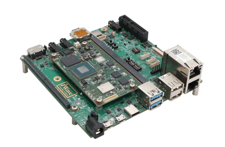
AAEON RICO-3568 is a Pico-ITX Plus single board computer powered by a Rockchip RK3568 quad-core Cortex-A55 AI SoC, up to 8GB LPDDR4, 16GB eMMC flash, four display interfaces (HDMI, LVDS, eDP, MIPI DSI), gigabit Ethernet, and various expansion headers for industrial applications.
Most have already heard about the Pico-ITX form factor, But it’s the first time I’ve ever come across a Pico-ITX Plus board. It looks like it’s an AAEON-specific “standard” right now, with the Pico-ITX Plus boards (100x8
AAEON RICO-3568 is a Pico-ITX Plus single board computer powered by a Rockchip RK3568 quad-core Cortex-A55 AI SoC, up to 8GB LPDDR4, 16GB eMMC flash, four display interfaces (HDMI, LVDS, eDP, MIPI DSI), gigabit Ethernet, and various expansion headers for industrial applications.
Most have already heard about the Pico-ITX form factor, But it’s the first time I’ve ever come across a Pico-ITX Plus board. It looks like it’s an AAEON-specific “standard” right now, with the Pico-ITX Plus boards (100x80mm) being slightly wider than Pico-ITX SBCs (100x72mm).
The T650 daughter board – also referred to as the PER-T650 – looks interesting, but I was unable to find any specifics at the time of writing. AAEON provides Android 12 and Debian 10 support for the board, and currently available documentation includes a datasheet and user manual mostly focusing on the hardware.
The company says the board is a robust, fanless industrial-grade solution for applications such as automation, digital signage, and edge computing.
Block Diagram
The only other “PICO-ITX Plus” SBC I could find is the upcoming RICO-MX8M (see PDF brief) with an NXP i.MX 8M Mini SoC, many of the same features, and a 40-pin Raspberry Pi header. It’s unclear why the company decided to create a new form factor unless the required features would not fit in the standard 100x72mm Pico-ITX form factor, and the extra 8mm made all the difference. I’ve asked, but I’ll update this post if I receive a reply. Having said that, it’s not the first company to mess with the Pico-ITX form factor, as Radxa designed a “PI-CO ITX SBC” that combines the benefits of Pico-ITX and Raspberry Pi form factors.
AAEON did not provide price and availability information. More details, including the aforementioned user manual and datasheet, can be found on the product page, and you may also get additional tidbits of information in the press release.
The reComputer R1025-10 is a Raspberry Pi CM4-based DIN Rail industrial gateway and edge IoT controller designed by Seeed Studio. The company mentions that the R1025-10 is the first module in the reComputer R1000 series and it’s equipped with 4GB RAM and 32GB of eMMC version of the CM4 module. That simply means the company will launch Edge IoT controllers in the series which will host different variants of the CM4 module.
The R1025-10 gateway is features rich and includes two Ethernet interfaces
The reComputer R1025-10 is a Raspberry Pi CM4-based DIN Rail industrial gateway and edge IoT controller designed by Seeed Studio. The company mentions that the R1025-10 is the first module in the reComputer R1000 series and it’s equipped with 4GB RAM and 32GB of eMMC version of the CM4 module. That simply means the company will launch Edge IoT controllers in the series which will host different variants of the CM4 module.
The R1025-10 gateway is features rich and includes two Ethernet interfaces, three isolated RS485 interfaces, and a variety of optional wireless modules including 4G, LoRa, Zigbee, or Wi-Fi/BLE. Other features include an HDMI port, two USB Type-A ports, and a USB Type-C 2.0 port.
Memory – 4GB DDR4 (1GB/2GB/4GB/8GB options for R1000 series)
Storage – 32GB eMMC storage (8GB/16GB/32GB options for the R1000 series)
Optional wireless module
Storage – M.2 slot for M.2 NVMe SSD
Video Output – 1 x HDMI 2.0 4Kp60
Networking
Wired
Gigabit Ethernet RJ45 port with optional PoE
10/100Mbps Ethernet RJ45 port (IEEE802.3/802.3u)
Wi-Fi 2.4/5.0 GHz on-chip Wi-Fi (optional)
BLE 5.0 on-chip BLE (optional)
LoRa: USB LoRa/SPI LoRa (optional)
Cellular: 4G LTE (optional)
Zigbee: USB Zigbee (optional)
USB
2 x USB-A 2.0 host
1 x USB-C 2.0 for flashing OS
Encryption – TPM 2.0 via ATECC608A chip (optional)
Additional Features
Hardware Watchdog – 1~255s
High Accuracy RTC
1 x Buzzer
6 x LED indicators
Reset Button
SuperCAP UPS LTC3350 Module (optional)
Powering options
Input – 2-pin Terminal Block
Supply Voltage: 12 – 24V AC / 9 – 36V DC
PoE (as powered device): IEEE 802.3af Standard 12.95W PoE
Power Consumption: Idle: 2.88W; Full Load: 5.52W
EMC Standards
ESD – EN61000-4-2, Level 3
EFT – EN61000-4-4, Level 2
Surge – EN61000-4-5, Level 2
Environmental specifications
Ingress Protection – IP40
Operating Temperature: -30~70°C
Operating Humidity – 10~95% RH
Storage Temperature: -40~80°C
Certifications – CE, FCC, TELEC, RoHS
Production Lifetime – Until December 2030
Dimensions – 130 x 93 x 45 mm
The company mentions that the body of the module is made up of high-impact resistant materials of 6061 aluminum alloy casing with transparent PC side panels to withstand harsh conditions. the device also has vibration and shock resistance standards and exceeds Electrostatic Discharge (ESD), Electrical Fast Transient (EFT), and Surge immunity levels.
The R1025-10 is a ready-to-deploy Industrial IoT (IIoT) controller with pre-configured firmware, simplifying setup and reducing time to deployment. Additionally, it offers flexible installation options with both wall mount and DIN rail mount compatibility.
The module has support for Modbus UDP/TCP and BACnet protocols, making it suitable for controlling HVAC systems and other subsystems like lighting, sensors, and access control in smart buildings. It also supports Yocto and Buildroot meaning you can customize Linux distribution to run on your device and provide a convenient solution for managing software updates. There is also support for Fleet management tools like Mender for easy device management and deployment. But at the time of writing, the GitHub page does not provide any specific OS image software for this specific gateway.
For more information about the reComputer R1025-10 IoT gateway, please visit the Getting Started guide with a hardware overview, project examples, additional module information, and other helpful resources. The reComputer R1025-10 Edge IoT Controller is currently available for backorder for $209.00 and is expected to ship on May 31, 2024.
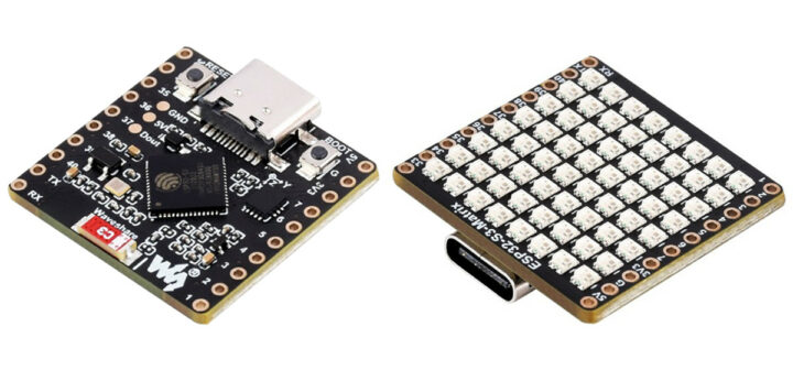
Voidbox FLIP_C3 is an open-source hardware board powered by an ESP32-C3 WiFi & BLE microcontroller that takes up to 60V DC power input feeding a 5V/2A DC-DC step-down converter and flashed with ESPHome firmware by default for Home Assistant support.
The board incorporates a push-in spring release connector which means stranded (ferrules or tinning are suggested) and solid wires can be used in deploying the device in off-grid/battery-powered systems with up to 16s LiFePO4 delivering 48V thro
Voidbox FLIP_C3 is an open-source hardware board powered by an ESP32-C3 WiFi & BLE microcontroller that takes up to 60V DC power input feeding a 5V/2A DC-DC step-down converter and flashed with ESPHome firmware by default for Home Assistant support.
The board incorporates a push-in spring release connector which means stranded (ferrules or tinning are suggested) and solid wires can be used in deploying the device in off-grid/battery-powered systems with up to 16s LiFePO4 delivering 48V through the 6-60V input port on the ESP32-C3 board. The onboard WS2812B LED can be used as a null pixel/level shifter for longer strings of addressable pixels.
The ESP32-C3 – due to its support for Wi-Fi and BLE connectivity – is a popular SoC for IoT solutions and powers home and industrial automation devices such as NanoCell v2.1, Spark Analyzer, LOLIN C3 Pico, and the LILYGO T-RSC3.
It is built for home automation applications and comes with ESPHome preloaded for easy integration with Home Assistant. However, it is easy to install other firmware such as Tasmota and WLED on the device via USB-C and over-the-air updates.
FLIP_C3 specifications:
Microcontroller – ESP32-C3 RISC-V MCU @ 160 MHz, with Wi-Fi and BLE 5 connectivity pre-loaded with ESPHome for Home Assistant
USB – USB-C for alternative power and programming; reverse current protection from DC input via diode
Expansion
I2C and UART on JST SH1.0 4-pin connectors compatible with Stemma QT and Qwiic modules
9-pin + 10-pin headers with GPIO, I2C, UART, 5V,. 3.3V, and GND
Onboard LEDs
WS2812B RGB LED with D-Out sent to L8 on pin header
Status LED
Buttons – Boot, Reset
Onboard 5V/2A buck converter
Power – Up to 10W (with cooling)
Tolerant up to 50V DC for direct connection
60V absolute max (with pre-charge resistor)
Push-in, spring terminal for DC input
Solid: 24 – 16 AWG
Stranded: 22 – 18 AWG
2x2P 2/54 pass-through power header for stacking
Typical applications of the FLIP_C3 board include:
Deploying short runs of addressable LEDs using level-shifted output from WS2182B, and
Reading Daly BMS data via UART and using the onboard buck converter to supply power from a 14s Li-ion or 16s LiFePo4 pack.
The board is open-source and hardware files are hosted on OSHWLab. A 3D DIN rail mount can be downloaded from printables.
First came the ROCK 5B pico-ITX SBC, then the Raspberry Pi 4-sized ROCK 5A board, and now Radxa has launched the Radxa ROCK 5C and 5C Lite single board computers powered by respectively Rockchip RK3588S2 octa-core and RK3582 hexa/octa-core “Lottery” processors.
The ROCK 5C (Lite) design is very similar to the ROCK 5A, but there are some notable differences. First, it replaces the two micro HDMI ports with a single HDMI port, then it removes the Key M socket for M.2 wireless modules to make place
First came the ROCK 5B pico-ITX SBC, then the Raspberry Pi 4-sized ROCK 5A board, and now Radxa has launched the Radxa ROCK 5C and 5C Lite single board computers powered by respectively Rockchip RK3588S2 octa-core and RK3582 hexa/octa-core “Lottery” processors.
The ROCK 5C (Lite) design is very similar to the ROCK 5A, but there are some notable differences. First, it replaces the two micro HDMI ports with a single HDMI port, then it removes the Key M socket for M.2 wireless modules to make place for a built-in WiFi 6 and Bluetooth 5.4 module plus a Raspberry Pi PCIe FFC connector, and finally, the ROCK 5C does not support an SPI flash module anymore.
The specifications of the ROCK 5C and ROCK 5 Lite SBC can be found in the table below.
Model
ROCK 5C
ROCK 5C Lite
SoC
Rockchip RK3588S2
Rockchip RK3582
CPU
Quad-core Cortex-A76 with up to 2.4 GHz
Quad-core Cortex-A55 at up to 1.8GHz
Dual-core Cortex-A76 with up to 2.4 GHz
Quad-core Cortex-A55 at up to 1.8GHz
GPU
Arm Mali‑G610MC4
N/A
NPU
6 TOPS NPU
5 TOPS NPU
RAM
2GB, 4GB, 8GB, 16GB, or 32GB 64-bit LPDDR4x
1GB, 2GB, 4GB, 8GB, or 16GB 64-bit LPDDR4x
Storage
eMMC module connector
microSD Card
No SPI flash
Video Output
HDMI 2.1 up to 8K
MIPI DSI up to 2K
Multimedia
H.265 and VP9 decoder up to 8Kp60
H.264 decoder up to 8Kp30
AV1 decoder up to 4Kp60
H.264 and H.265 encoder up to 8Kp30
H.264 and H.265 encoder up to 4Kp60
Camera
1x4 lane MIPI CSI
Ethernet
Gigabit Ethernet with optional PoE
Wireless
WiFi 6 and Bluetooth 5.4 with antenna connector
USB
2x USB 2.0 ports
1x USB 3.0 host port
1x USB 3.0 OTG port
Expansion
Raspberry Pi FFC PCIe 2.1 x1 connector
40-pin Raspberry Pi GPIO header
Power Supply
5V via USB-C port
Dimensions
86 x 56 mm
Radxa ROCK 5C with RK3588S2 SBC
Both processors are new, so let’s have a look. First, how does RK3588S2 differ from RK3588S? They are basically the same except the RK3588S2 comes with an additional MIPI CSI interface which is not used in the ROCK 5C. The Rockchip RK3582 is also an RK3588S SoC but with some missing and cut-down features. Why do I call it a “lottery” processor? First, when chips are manufactured they have different capabilities on the wafer, and that’s why Intel has processors with the same die and features but different CPU and GPU frequencies. Some processors that mostly work but miss some features may be discarded impacting the yield. As I understand it that’s what Rockchip did with the RK3582, those are just RK3588S parts that would be previously discarded. That also explains why Radxa says that in some cases RK3582 may get four Cortex-A76 cores and/or a GPU. That’s the RK3582 lottery
Having said that, all advertised features of the RK3582 will work, and people will get at least a hexa-core Cortex-A76/A55 processor, no GPU, a 5 TOP NPU, and a 4K video encoder. We previously received the Rockchip RK3582 datasheet and the 4K video decoders are listed there. Maybe it was a preliminary datasheet, and those are not guaranteed to work anymore on the RK3582.
Radxa ROCK 5C accessories
The presence of a 40-pin Raspberry Pi header and Raspberry Pi PCIe FFC connector means the ROCK 5C/5C Lite will also work with Raspberry Pi HAT+ including the ones made for the Raspberry Pi 5 such as the Waveshare PCIe to M.2 HAT or the official Raspberry Pi M.2 HAT+. It’s the second non-Pi single board computer with the 16-pin PCIe connector we’ve seen after the Kaki Pi, but the ROCK 5C will offer better compatibility since the connector is in the same position as the Pi 5. Radxa also made its own accessories with the heatsink 6540B active cooler, a PoE HAT, a few eMMC modules, and 8-inch and 10-inch displays.
Software-wise, Radxa provides the Debian-based Radxa OS and detailed documentation to get started, for low-level development, and for application development. You can also directly access the build script for Radxa OS on GitHub. Android is also being worked on but not available just yet, and I’m sure community-supported images will also be released.
Radxa OS
Radxa ROCK 5C Lite sells for $51.53 on Aliexpress with 4GB RAM(Note: the 1GB model would go for $34.35, but it’s out of stock), and the Raxa ROCK 5C starts at $57.11 (2GB) or $68.56 (4GB) on the same page, meaning variants with RK3582 are about $17 cheaper than the ones based on RK3588S. Accessories such as the heatsink, displays, and eMMC modules can also be purchased from the relevant section on the company’s Aliexpress store. Additional information may be found on the product page.
The e Foundation has just announced the release of the /e/OS v2 Android-based Google-free open-source mobile operating system with an improved launcher, support for Android Auto, a “Wall of Shame” to identify the most leaking apps and tracker, QR Code scanning support in the camera app, and more.
Most Android smartphones come with Google services which may be convenient (and help keep Android free), but come at the loss of the users’ privacy. That’s why the e Foundation started offering e/OS ove
The e Foundation has just announced the release of the /e/OS v2 Android-based Google-free open-source mobile operating system with an improved launcher, support for Android Auto, a “Wall of Shame” to identify the most leaking apps and tracker, QR Code scanning support in the camera app, and more.
Most Android smartphones come with Google services which may be convenient (and help keep Android free), but come at the loss of the users’ privacy. That’s why the e Foundation started offering e/OS over five years ago to offer a privacy-focused version of Android without Google services on specific phones. The project has evolved over the years, over 200 mobile devices are supported officially and unofficially, and Murena, a for-profit company, has also been established to sell e/OS smartphones and cloud services.
/e/os v1 screenshots (could not find any for /e/os v2)
/e/OS v2 highlights and changes:
Based on LineageOS 20 with the latest bug fixes and security updates (itself based on Android 13)
Upgraded Launcher with live wallpaper support, notifications improvements, and various bug fixes. It also comes with new icons and wallpapers
Support for Android Auto. See documentation for details (Note it’s relying on Google Maps)
QR code scanning is now available in Camera app
Advanced Privacy setting – Wall of Shame added to the homepage to identify the most leaking apps and trackers; UI improvements
Updated to version 1.5 of eDrive for more stability of file synchronization
Browser updated to version 123.0.6312.122 from upstream and sensor exposure is reenabled
You’ll find more changes and bug fixes in the release notes. You may also watch the launch video below for more information and some Q&A from viewers.
/e/OS v2 is apparently still using Google Maps (at least for Android Auto) and users can still log in to services with their Google/Gmail account, so here’s what “deGoogled OS” means:
/e/OS is a “deGoogled” version of Android OS. It has an open-source Android OS core, with no Google apps or Google services accessing your personal data.
Google default search engine has been removed from the OS everywhere and replaced with our meta-search engine
We do not use Google’s Network Time Protocol servers
We do not use Google’s Domain Name System servers
Geo-location uses Mozilla Location Services in addition to GPS.
Murena Fairphone 5
There are 250 devices currently supported /e/os mobile OS either by the community or with official support (22 devices). So the level of support may differ, and it’s unclear whether all are upgradable to /e/os v2. In most cases, you’ll need to install the mobile OS by ourself, but you can also purchase a Murena smartphone preinstalled with /e/os starting with the Murena One going for 199.99 Euros, and there are other higher-end devices such as the Murena Fairphone 5 available on the same shop. As mentioned in the introduction, Murena also offers a cloud service called “Murena Cloud” that acts as your personal email account, agenda and contacts, cloud drive, and office suite based on NextCloud and OnlyOffice.
The Waveshare ESP32-S3 1.69-inch touch display is a development board that uses an ESP32-S3 as the main controller. The board features a 240×280 touchscreen LCD that supports 262K colors and is equipped with an accelerometer, gyroscope, RTC, battery management IC, and a USB-C port for programming and power.
Previously we wrote about the Waveshare ESP32-S3-LCD-1.28 1.28-inch fully rounded LCD screen that is also built around an ESP32-S3 MCU, and we have also recently written about the similar-loo
The Waveshare ESP32-S3 1.69-inch touch display is a development board that uses an ESP32-S3 as the main controller. The board features a 240×280 touchscreen LCD that supports 262K colors and is equipped with an accelerometer, gyroscope, RTC, battery management IC, and a USB-C port for programming and power.
Previously we wrote about the Waveshare ESP32-S3-LCD-1.28 1.28-inch fully rounded LCD screen that is also built around an ESP32-S3 MCU, and we have also recently written about the similar-looking Waveshare 1.69-inch IPS touch LCD with no onboard MCU that is meant to connect to Raspberry Pi, ESP32-S3, Raspberry Pi Pico, Arduino, STM32, and other boards with I2C or SPI interfaces.
PWR Button with single-press, double-press, multi-press, and long-press operations.
The WaveshareESP32-S3-Touch-LCD-1.69 development board is compatible with CircuitPython and MicroPython, as well as C/C++ programming using Arduino and ESP-IDF. Users can easily download the MicroPython firmware and find additional resources on the Waveshare Wiki page to get started.
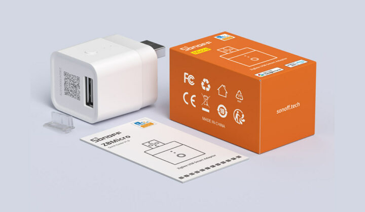
SONOFF Zigbee Bridge Ultra, also known as ZBBridge-U, is a Zigbee 3.0 gateway and Matter Bridge powered by a 1.5 GHz Rockchip RV1109 dual-core processor and equipped with Silicon Labs EFR32MG21 multiprotocol SoC.
The gateway also offers WiFi and Ethernet connectivity and supports up to 256 Zigbee 3.0 sub-devices improving on the 128 sub-devices supported by the earlier SONOFF ZBBridge-P (ESP32+CC2652P) that also lacks Matter support. The new ZBBridge-U gateway further implements a Turbo mode inc
SONOFF Zigbee Bridge Ultra, also known as ZBBridge-U, is a Zigbee 3.0 gateway and Matter Bridge powered by a 1.5 GHz Rockchip RV1109 dual-core processor and equipped with Silicon Labs EFR32MG21 multiprotocol SoC.
The gateway also offers WiFi and Ethernet connectivity and supports up to 256 Zigbee 3.0 sub-devices improving on the 128 sub-devices supported by the earlier SONOFF ZBBridge-P (ESP32+CC2652P) that also lacks Matter support. The new ZBBridge-U gateway further implements a Turbo mode increasing the line-of-sight range to up to 200 meters.
SoC – Rockchip RV1109 dual-core Arm Cortex-A7 @ 1.5 GHz with RISC-V MCU @ 400 MHz, 2D graphics engine, 1.2 TOPS NPU, 5MP H.264 and H.265 hardware video decoder and encoder
System Memory – 1GB DDR4
Storage – 8GB eMMC flash for the OS
Connectivity
10/100M Ethernet RJ45 port
2.4GHz WiFi 4
Zigbee 3.0 via Silicon Labs EFR32MG21 SoC with up to 200 meters range with Turbo mode
Acts as a Zigbee to Matter Bridge
Misc
Button
Press and hold for 3 seconds: enters pairing mode (for up to 30 minutes)
Press and hold for 10 seconds: Factory Reset
Single press button: Exit pairing mode or cancel alarm
Tri-color LED
Power Supply – 5V/1A via USB Type-C port
Dimensions – 82 x 82 x 28 mm (PC+ABS plastic enclosure)
Weight – 92.5 grams
Temperature Range – -10 to +40°C
Humidity – 5% to 95% RH, non-condensing
Certifications – CE/FCC/ISED/RoHS
Safety Standard – EN 62368-1
Based on the specifications alone, the ZBBridge-U looks like a cost-down SONOFF iHost hub without audio, a micro SD card, a USB Type-A port, and fancy RGB LEDs. The company confirmed with us the system primarily caters to users within the eWelink ecosystem and SONOFF products. It doesn’t support Zigbee devices from other manufacturers right now (I suppose except those that are Matter compatible) and there’s nothing about Home Assistant integration.
What users can do is keep the Zigbee Bridge Ultra and their Matter hub in the same LAN with SONOFF Zigbee sub-devices such as SNZB-06P human presence sensor, ZBMINIL2 Zigbee switch, S26R2ZB smart plug, SNZB-03P Zigbee motion sensor, etc… synchronizing with Matter-compatible hubs supporting Amazon Alexa, Google Home, Apple Home, or SmartThings. SONOFF also explains the gateway can be used as an alarm where the user sets a scene triggered by an NFC tap, a wireless button, or an app remote control. When an event is triggered, you will hear a beep and receive a notification push. The user manual has more information.
Switching from an ESP32 device to a Linux-capable bridge (plus Matter certification) does add to the cost, as while the previous generation SONOFF Zigbee Bridge Pro now goes for $19.90, the new SONOFF Zigbee Bridge Ultra sells for $59.90. As usual, you can lower the price by using CNXSOFTSONOFF coupon to get a 10% discount on any order on the ITEAD website or use the Zigbee15 coupon code for a 15% discount on Zigbee products for a limited time.
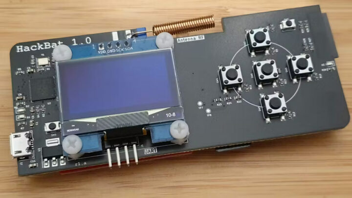
HackBat is an open-source hardware pen-testing device designed for hackers and makers and equipped with a Raspberry Pi RP2040 microcontroller, an ESP8266 WiFi module, a sub-GHz RF transceiver, NFC, an OLED display, and more… It’s basically a DIY alternative to the popular Flipper Zero wireless hacking tool, that you can produce and assemble yourself.
The Flipper Zero was the victim of its own success with the Canadian government (wrongly) claiming it could easily be used for car theft and planni
HackBat is an open-source hardware pen-testing device designed for hackers and makers and equipped with a Raspberry Pi RP2040 microcontroller, an ESP8266 WiFi module, a sub-GHz RF transceiver, NFC, an OLED display, and more… It’s basically a DIY alternative to the popular Flipper Zero wireless hacking tool, that you can produce and assemble yourself.
The Flipper Zero was the victim of its own success with the Canadian government (wrongly) claiming it could easily be used for car theft and planning to ban it (status still unclear right now), so Flipper Zero alternatives such as the M1 multitool device got some traction as backup solutions with some extra features. But any closed-source device could eventually be banned, something that’s close to impossible for an open-source hardware device like the HackBat although policymakers could still decide to impose heavy fines if they wanted to make this type of device illegal…
HackBat key features and specifications:
Microcontroller – Raspberry Pi RP2040 dual-core Cortex-M0 processor at 133MHz and 264kB RAM.
Storage
4MB (32Mbit) flash by default
MicroSD card slot
Display – 0.96-inch OLED with 128×64 resolution connected (SH110X driver); note: OLED with SSD1306 are also supported but the VCC and GND pins are reversed and two 0 Ohm resistors need to be soldered
Wireless
Texas instruments CC1101 sub-1 GHz transceiver with coil antenna (and optional SMA antenna connector) supporting 315, 433, 868, and 915 MHz bands as well as the 300-348 MHz, 387-464 MHz and 779-928 MHz bands
ESP-12F ESP8266 module connected over UART to RP2040 and programmable through the RP2040 used as USB-UART bridge.
USB – 1x micro USB port for power, programming (RP2040 and ESP8266), and keyboard emulation
User control – 5-key D-Pad
Misc – 2x user LEDs, two extra system buttons
Power Supply – 5V via micro USB port
Dimensions – 100 x 42 mm
Bottom side of the HackBat board with an NFC module, a microSD card slot, and an ESP12-F module
You’ll find the KiCad hardware design files including schematics, PCB layout, BoM, and Gerbers along with some documentation on GitHub, and as well as on Hackster.io. Since the HackBat is not for sale, you’d have to manufacture the PCB and do some soldering, or order the PCBA directly. If you’ve never done that, we reported our experience ordering PCBAs for another open-source hardware board using NextPCB a few years ago. It’s feasible, but you’ve never done that it will require some effort, even though the PCB design part is already done…
The other part of this DIY project would be the firmware, because Pablo Trujillo, the maker of the board, has yet to share any firmware, so unless things change, you’d also have to write your own RP2040 firmware to play with the HackBat. Luckily, it’s mostly based on off-the-shelf parts with available Arduino libraries which should somewhat simply the programming part.
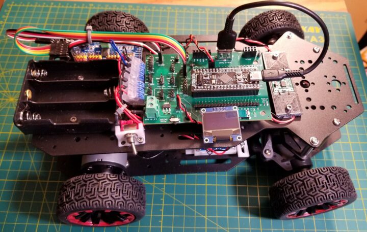
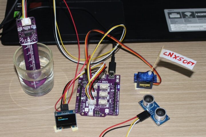
The Car Base Board from Applying Microcontroller Solutions is a modular platform for building robot car projects powered by the WeAct Studio Black Pill development board. The Black Pill board is an upgrade to the “Blue Pill 2” board and features the STM32F411CEU6 microcontroller running at 100MHz with 512 KB of flash memory, 128 KB SRAM, and a USB Type-C port for power and programming.
The Care Base Board printed circuit board is a base controller that takes hardware expansions such as wireless
The Car Base Board from Applying Microcontroller Solutions is a modular platform for building robot car projects powered by the WeAct Studio Black Pill development board. The Black Pill board is an upgrade to the “Blue Pill 2” board and features the STM32F411CEU6 microcontroller running at 100MHz with 512 KB of flash memory, 128 KB SRAM, and a USB Type-C port for power and programming.
The Care Base Board printed circuit board is a base controller that takes hardware expansions such as wireless modules, servos, and sensors to monitor and control a robot car. The onboard headers provide a straightforward way to wire these connections and help prevent a tangled mess (rat’s nest) of wires.
The PCB’s design makes it easy to use widely-available, “generic” devices and boards in development and to power all of them with batteries. It also allows the developer to select their favorite wireless communication device. The Car Base Board adds another option to robotics development platforms we have previously covered such as M5Stack BugC2, EVN Alpha, and the Qualcomm RB5 platform.
Applying Microcontroller Solutions Car Base Board specifications:
Supported MCU board – Weact Black Pill board based on STM32F411 Arm Cortex-M4F MCU @ 100 MHz with 512KB on-chip flash, 128KB on-chip SRAM, and 8 MB or 16 MB Flash (important since the flash is not present on all versions of the Black Bill)
Motor Control
6-pin connector for dual motor control
PCA9685 Servo Driver connector (6V servos)
2x 3-pin Servo connector (5V servos)
Monitors/Sensor for obstacle avoidance
Ultrasonic (SR-HC04/05)
2x infrared slotted optical speed sensor
3x infrared obstacle sensor/tracker
Communication
Infrared Receiver (IR1838)
6-pin UART port for connecting a Bluetooth module
NRF24 for 2.4GHz communication
Display – I2C port for OLED display
Power
4.5 – 5.0V USB power from desktop computer via USB-C connector on Black Pill (3.3V power to Car Base Board)
Battery power from an external source via onboard Phoenix connector (5V to several headers via 5V regulator)
The Black Pill development can be programmed in STM32 C, Arduino, or MicroPython. Working MicroPython examples for different devices are available in the Base Board’s Github repository.
Car Base board mounted on Ackermann robot car chassis ($69 on Amazon)
The Car Base Board is available for $14 on Tindie. Do note that the board is just the base controller, and you will need to acquire the STM32 BlackPill, vehicle chassis, modules, ribbon cables, battery, and other components yourself. The seller mentions that they may offer “an add-on product containing the devices, wiring, and chassis” if sufficient interest is indicated. More information is available in the GitHub repository.
Jean-Luc noted the MemryX MX3 edge AI accelerator module while covering the DeGirum ORCA M.2 and USB Edge AI accelerators last month, so today, we’ll have a look at this AI chip and corresponding modules that run computer vision neural networks using common frameworks such as TensorFlow, TensorFlow Lite, ONNX, PyTorch, and Keras.
MemryX MX3 Specifications
MemryX hasn’t disclosed much performance stats about this chip. All we know is it offers more than 5 TFLOPs. The listed specifications include
Jean-Luc noted the MemryX MX3 edge AI accelerator module while covering the DeGirum ORCA M.2 and USB Edge AI accelerators last month, so today, we’ll have a look at this AI chip and corresponding modules that run computer vision neural networks using common frameworks such as TensorFlow, TensorFlow Lite, ONNX, PyTorch, and Keras.
MemryX MX3 Specifications
MemryX hasn’t disclosed much performance stats about this chip. All we know is it offers more than 5 TFLOPs. The listed specifications include:
Bfloat16 activations
Batch = 1
Weights: 4, 8, and 16-bit
~10M parameters stored on-die
Host interfaces – PCIe Gen 3 I/O and/or USB 2.0/3.x
Power consumption – ~1.0W
1-click compilation for the MX-SDK when mapping neural networks that have multiple layers
Under the hood, the MX3 features MemryX Compute Engines (MCE) which are tightly coupled with at-memory computing. This design creates a native, proprietary dataflow architecture that utilizes up to 70% of the chip with just one click compared to 15-30% on traditional CPUs, GPUs, and DSPs that use legacy instruction sets and control-flow architectures after software tuning.
MemryX MX3 internal design
Form Factor
Form-factor-wise, this edge AI processor is offered either as a bare die, a single-die package, or in modules (mini PCIe or M.2) with one or more MemryX MX3 chips.
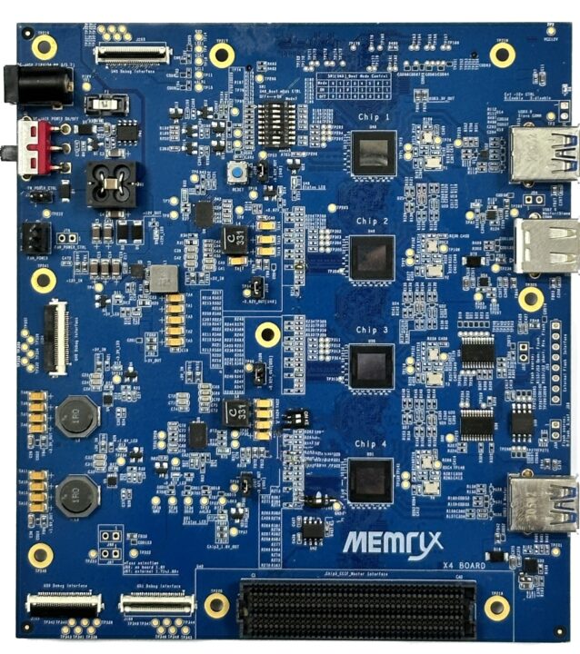
The MX3 EVB (Evaluation Board) is a PCBA with four MX3 chips, and you can cascade multiple EVB boards using a single interface to provide the required inferencing power. Each of these four chips has a single-die package.
MX3 SDK
The MX SDK helps in simulating and deploying the trained AI models. MemryX builds its products to:
Provide real-world performance per watt
Run models trained on any popular framework without requiring software changes or retraining
Provide high scalability and granularity
Run AI models equally as well on every host processor regardless of the system load
Provide the same 1-click SDK (compilation software)
This SDK’s developer hub consists of a compiler (for graph processing, mapping, and assembling), utility tools (a bit-accurate simulator, performance analyzer, profiler, chip helper tools, and template applications), and a runtime environment with APIs, OS drivers, and a dataflow runtime.
MX3-SDK architecture
You can use the MX3 EVB with Edge Impulse deployments after installing dependencies like Python 3.8+, MemryX tools and drivers, and Edge Impulse (for Linux). Next, connect the board to Edge Impulse, then verify it is connected by going to your projects and clicking “devices”.
MemryX MX3 demo
While the company hasn’t provided much detail about the chip’s performance, they did upload a video demo using the virtual camera input of AirSim – a software that creates datasets for autonomous driving and flying – comparing a computer fitted to an MX3 M.2 module to one equipped with NVIDIA 4060 GPU.
Latency was very low while running on the MX3 module, but increased drastically when switching over to the NVIDIA 4060 GPU, and the loud noise from the cooling fans was clearly noticeable.
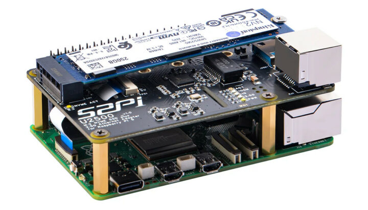
Designed specifically for the Raspberry Pi 5 SBC, the 52Pi W01 U2500 HAT offers support for M.2 M-key NVMe SSDs (2230, 2242, 2260, and 2280) along with a 2.5GbE (2.5 Gbps Ethernet port) using a Realtek RTL8156BG chipset.
The most interesting thing about this board is its connectivity – the M.2 SSD is driven directly by the Raspberry Pi’s PCIe port that supports Gen2 & Gen3 standards. However, the 2.5Gbps Ethernet port requires a connection to one of the Pi’s USB ports using a specialized USB
Designed specifically for the Raspberry Pi 5 SBC, the 52Pi W01 U2500 HAT offers support for M.2 M-key NVMe SSDs (2230, 2242, 2260, and 2280) along with a 2.5GbE (2.5 Gbps Ethernet port) using a Realtek RTL8156BG chipset.
The most interesting thing about this board is its connectivity – the M.2 SSD is driven directly by the Raspberry Pi’s PCIe port that supports Gen2 & Gen3 standards. However, the 2.5Gbps Ethernet port requires a connection to one of the Pi’s USB ports using a specialized USB-to-USB adapter included by 52Pi.
NVMe SSD support – Supports M-key NVMe SSDs in sizes 2230, 2242, 2260, and 2280
Networking – 2.5Gbps Ethernet with Realtek RTL8156BG chipset (externally connects to the Pi via USB adapter)
Host interfaces – Raspberry Pi 5 PCIe FFC connector (30mm FFC cable provided) up to PCIe Gen2 or Gen3 x1 speeds and 40-pin GPIO header
Misc – LED indicator for M.2 disk activity.
Power Management
Voltage regulator 3A on the 3.3V rail, compliant with M.2 standard.
Requirements
USB 2.5Gbps Ethernet: +5V, 650mA
NVMe SSD – Power consumption depends on the SSD used.
Dimensions – 85 x 56 x 15.15mm
The device is plug-and-play, so you just need to connect the power and it’ll work as intended. 52Pi also mentions the hollow design enables excellent ventilation and cooling, ensuring optimal performance. You can check out their wiki page for further information about the HAT.
W01 U2500 kit content
The package includes everything you need to attach the HAT to your Raspberry Pi 5. Inside, you’ll find the W01 U2500 USB 2.5Gbps Ethernet + NVMe HAT, eight M2.5x4mm flat head screws, two 8.5x40mm PCIe FFC cables, a 40-pin PC104 pin header, four M2.5x17mm copper pillars, an M2 iron pillar for securing your SSD, and a handy screwdriver.
Several companies have unveiled SMARC 2.1 compliant system-on-modules powered by the NXP i.MX 95 AI SoC, and today we’ll look at the ADLINK LEC-IMX95 and iWave Systems iW-RainboW-G61M and related development/evaluation kits.
The NXP i.MX 95 SoC was first unveiled at CES 2023 with up to six Cortex-A55 application cores, a Cortex-M33 real-time core, and a low-power Cortex-M7 core, as well as an eIQ Neutron NPU for machine learning applications. Since then a few companies have unveiled evaluation k
Several companies have unveiled SMARC 2.1 compliant system-on-modules powered by the NXP i.MX 95 AI SoC, and today we’ll look at the ADLINK LEC-IMX95 and iWave Systems iW-RainboW-G61M and related development/evaluation kits.
The NXP i.MX 95 SoC was first unveiled at CES 2023 with up to six Cortex-A55 application cores, a Cortex-M33 real-time core, and a low-power Cortex-M7 core, as well as an eIQ Neutron NPU for machine learning applications. Since then a few companies have unveiled evaluation kits and system-on-modules such as the Toradex Titan evaluation kit or the Variscite DART-MX95 SoM, but none of those were compliant with a SoM standard, but at least two SMARC 2.1 system-on-modules equipped with the NXP i.MX 95 processor have been introduced.
ADLINK LEC-IMX95
Specifications:
SoC – NXP i.MX 95
CPU
Up to 6x Arm Cortex-A55 application cores clocked at 2.0 GHz with 32K I-cache and D-cache, 64KB L2 cache, and 512KB L3 cache
1x Arm Cortex-M7 real-time core clocked at 800 MHz
1x Arm Cortex-M33 safety core clocked at 333 MHz
GPU – Arm Mali-G310 V2 GPU for 2D/3D acceleration with support for OpenGL ES 3.2, Vulkan 1.2, OpenCL 3.0
VPU
4Kp30 H.265 and H.264 encode and decode
JPEG Encoder, JPEG Decoder
AI Accelerator – NXP eIQ Neutron 2 TOPS neural processing unit (NPU) with 750 inf/sec
System Memory – 2GB, 4GB, or 8GB LPDDR5
Storage – 32GB, 64GB,128GB, or 256GB eMMC flash
Networking
2x RealTek RTL8211 GbE transceivers
Wireless (BoM option)
Wi-Fi 5 802.11ac/a/b/g/n 2X2 MIMO
Bluetooth 5.0 compliant with Bluetooth 2.1+Enhanced Data Rate (EDR)
314-pin MXM edge connector
Storage – SDIO (4-bit) compatible with SD/SDIO standard, up to version 3.0
Display interfaces
HDMI 2.0a (BoM option)
4-lane MIPI DSI
18/24 bit dual-channel LVDS
Camera – 4-lane MIPI CSI
Audio – 2x I2S or SWD audio codec located on carrier board; audio resolution from 16-bit to 32-bit and sample rate up to 192KHz
Networking
2x Gigabit Ethernet with Time Sensitive Networking (TSN)
Temperature Range – Standard: 0°C to 60°C; rugged: -40°C to 85°C
Humidity
Operating – 5-90% RH, non-condensing
Storage – 5-95% RH (and operating with conformal coating)
Shock and Vibration
EC 60068-2-64 and IEC-60068-2-27
MIL-STD-202F, Method 213B, Table 213-I, Condition A and Method 214A, Table 214-I, Condition D
HALT – Thermal Stress, Vibration Stress, Thermal Shock and Combined Test
The company provides standard support for Yocto Linux and Android, but extended support is also available for VxWorks. ADLINK will also offer the i-Pi SMARC iMX95 evaluation board with an I-Pi SMARC Plus carrier, an LEC-IMX95 SMARC module with NXP i.M95 and 4GB soldered LPDDR5 memory and 32GB eMMC, a 19V DC USB-C power adapter, and a micro USB cable. We have limited details about it but it will look like the I-Pi SMARC 1200 we’ve previously reviewed, just with a different system-on-module.
I-Pi SMARC 1200
All information is preliminary at this stage, and you can find more details on the product page for the NXP i.MX 95 SMARC 2.1 module as well as on the i-Pi website for the evaluation kit.
iWave iW-RainboW-G61M
iW-RainboW-G61M key features and specifications:
SoC – NXP i.MX 95 as described above
System Memory – 16GB LPDDR5
Storage – 16GB eMMC Flash and 16Mbit QSPI Flash
Wireless – Wi-Fi 6 & Bluetooth 5.3 connectivity
314-pin MXM edge connector
Storage – 4-bit SD
Display Interfaces – 2x LVDS, 1x HDMI
Camera – 4-lane MIPI CSI, 2-lane MIPI CSI
Audio – 2x I2S
Networking
2x Gigabit Ethernet interfaces
1x SerDes (10Gbps)
USB – 4x USB 2.0 Host, 1x USB 3.0 OTG
PCIe – 2x PCIe 3.0 x1
Other peripherals – 2x CAN, 3x I2C, 2x SPI, 2x UART with CTS & RTS, 1x UART without CTS & RTS, 14x GPIOs
Debug UART
Power Input – 5V/ 2.5A through SMARC Edge Connector
Software support is somewhat confusing as iWave Systems lists both a Linux 6.6 BSP and support for Linux 6.1.55… The company also provides an evaluation kit with access to all features from the SMARC system-on-module
Evaluation Kit main features:
Storage – SD card slot
Video Output – HDMI Type-A connector, 20-pin LVDS connector
Camera I/F – MIPI CSI camera connector
Audio – 2x Audio In & Out Jack through I2S codec
Networking – 2x Gigabit Ethernet RJ45 jacks
USB
2x USB 2.0 Host Type-A ports
1x USB 2.0 OTG Type microAB port
1x USB 3.0 Host Type-A port
1x USB 3.0 Type-C OTG port
2x CAN header
Expansion
1x PCIe slot
M.2 KEY-B PCIe socket
GPIO headers
Power Supply – 12V/2A via DC jack
Dimensions – 120x120mm (Nano-ITX motherboard)
i.MX 95 SMARC Development Kit Block Diagram
iWave Systems provides various enclosure and cooling solutions for the evaluation kit. More details about the SoM and devkit can be found on the product page.
We haven’t talked about pricing and availability yet. That’s because while NXP likely started offering i.MX95 processor samples to customers at the end of last year, the company is now expecting mass production to start in Q4 2024 or Q1 2025. I also noticed two other upcoming NXP i.MX95 SMARC modules, namely the Advantech ROM-5820 and Avnet SM2S-IMX95, so there will be plenty of options in due time.
Machdyne’s Blaustahl is a USB storage device equipped with a Raspberry Pi RP2040 MCU and 8KB of FRAM with a potential lifespan of over 200 years and designed for long-term storage of text up to about 8,000 characters.
FRAM (Ferroelectric RAM) has been around for years delivering ultra-low power consumption, faster writes, and ultra-long write endurance (one million billion read/write cycles) compared to EEPROM or NOR flash, but the cost is quite higher and it’s mostly used in applications that r
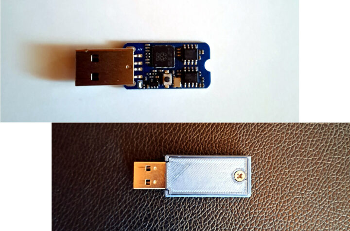
Machdyne’s Blaustahl is a USB storage device equipped with a Raspberry Pi RP2040 MCU and 8KB of FRAM with a potential lifespan of over 200 years and designed for long-term storage of text up to about 8,000 characters.
FRAM (Ferroelectric RAM) has been around for years delivering ultra-low power consumption, faster writes, and ultra-long write endurance (one million billion read/write cycles) compared to EEPROM or NOR flash, but the cost is quite higher and it’s mostly used in applications that require ultra-low power consumption and non-volatile storage write capabilities such as data logging, sensor networks, batteryless applications. The Blaustahl storage device and USB text editor is one of those.
Blaustahl bare board (top) and housed in an enclosure (bottom)
Blaustahl speciications:
Microcontroller – Raspberry Pi RP2040 dual-core Cortex-M0 processor at 133MHz and 264kB RAM.
Lifespan – 95 years @ +55°C, over 200 years @ +35°C
Endurance – 10^12 read/write cycles @ +85°C
Supports FRAM write protection via solder jumper
USB – 1x USB Type-A male port; USB-CDC interface requires no additional drivers on most OSes
Misc – Blue LED
Security – Encryption coming soon in updated firmware
Dimensions – Board: 30 x 16mm
Blue 3D-printed PLA case
USB text editor
The Blaustahl USB FRAM device runs a built-in text editor accessible through a serial communication program with VT100 emulation support such as PuTTY, Tera Term, Minicom, screen, etc… You’ll find the RP2040 firmware (code and binary), schematics (PDF), and SCAD file for the enclosure on GitHub. Potential applications include password storage, cryptocurrency private key/ seed phrase storage, note/list storage, geocaching, and time capsules, or users could simply use it as a small FRAM development board.
I also wondered how FRAM would compare to other storage solutions. We’ve already seen the Futjisu FRAM can last up to 200 years (if we stay within the huge read/write cycle limit) at 35°C, while a NOR flash is limited to up to 20 years at 55°C according to Infineon, and NAND flash is supposed to last 16 to 20 years in the same conditions according to data from Schweitzer Engineering Laboratories, Inc. EEPROM looks better with a 100 to 200 years data retention at 55°C, but with longer write times and significantly fewer write cycles than FRAM. All those will also depend on read/cycle cycles and other conditions like humidity levels. We also have to consider the complete device as if the RP2040 stops working after 30 years or the USB port becomes rusty to the point of being unusable, it does not matter that much to have a long-lasting FRAM chip although physical recovering methods (e.g. unsoldering) might still be possible.
Machdyne sells the Blaustahl USB FRAM storage device for 29.95 Euros and ships from Germany.
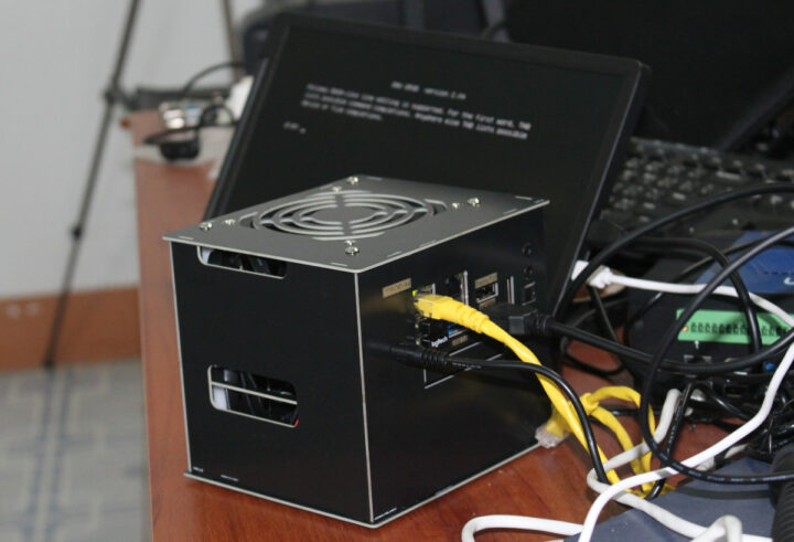
GEEKOM A8 is an AI mini PC based on the powerful AMD Ryzen 9 8945HS (or Ryzen 7 8845HS) AI processor with AMD Radeon 780M Graphics, up to 64GB DDR5 memory, up to 2TB M.2 NVMe SSD support for up to four display up to 8K resolution, and comes preloaded with Windows 11 Pro operating system.
The mini PC is equipped with two HDMI 2.1 ports, two USB-C ports with DisplayPort Alt mode, 4x USB 3.2 Type-A ports, 2.5GbE, a WiFi 6E and Bluetooth 5.3 module, and a stereo headset jack. GEEKOM sent us a sample
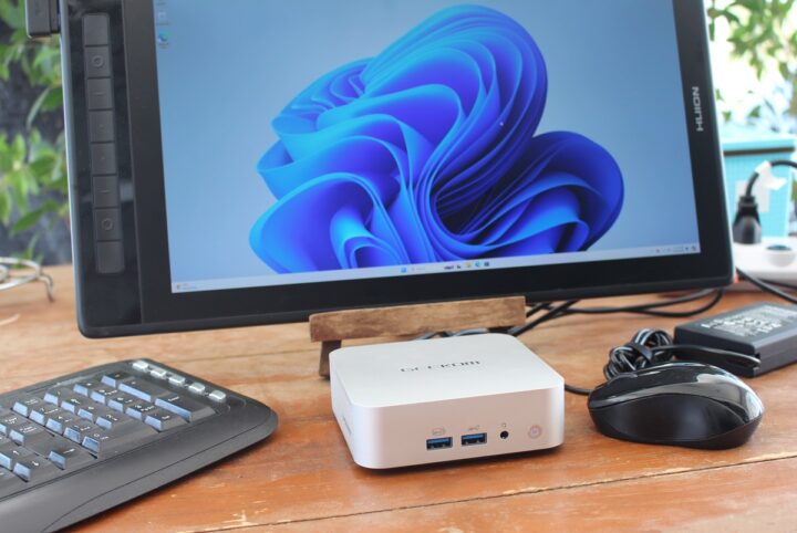
GEEKOM A8 is an AI mini PC based on the powerful AMD Ryzen 9 8945HS (or Ryzen 7 8845HS) AI processor with AMD Radeon 780M Graphics, up to 64GB DDR5 memory, up to 2TB M.2 NVMe SSD support for up to four display up to 8K resolution, and comes preloaded with Windows 11 Pro operating system.
The mini PC is equipped with two HDMI 2.1 ports, two USB-C ports with DisplayPort Alt mode, 4x USB 3.2 Type-A ports, 2.5GbE, a WiFi 6E and Bluetooth 5.3 module, and a stereo headset jack. GEEKOM sent us a sample of the A8 Mini PC with an AMD Ryzen 9 8945HS 8-core/16-thread processor, 32GB DDR5, and a 2TB M.2 NVMe SSD with Windows 11 Pro for review this time. We’ll start by listing some specifications, doing an unboxing, going through a teardown, and booting Windows 11. In the second and third parts of the review, we will test the performance and features on Windows 11 and Ubuntu 24.04 respectively.
CPU – 8-core/16-thread processor up to 3.8GHz / 5.1 (Turbo)
Cache – 16MB
GPU – AMD Radeon 780M Graphics
AI – NPU performance: 16 TOPS, total: 38 TOPS
TDP: 45W
System Memory – Dual-channel DDR5-5600 SODIMM, up to 64GB
Storage
M.2 2280 SSD socket (PCIe Gen4 x4 up to 2TB or SATA III up to 1TB)
Full-size SD card reader
Video Output
2x HDMI 2.0 ports
USB4 and USB 3.2 Type-C ports with DisplayPort Alt mode
Up to 4x independent displays
Audio – 3.5mm stereo headset jack; digital audio output via HDMI and USB-C
Networking
2.5GbE RJ45 port via RealTek RTL8125BG-CG controller
WiFi 6E and Bluetooth 5.3
USB
3x USB 3.2 Gen 2 Type-A
1x USB4 Type-C port with DisplayPort Alt mode, USB PD support
1x USB 3.2 Gen 2 Type-C port with DisplayPort Alt mode, USB PD support
1x USB 2.0 Type-A port
Misc – Power button
Power Supply – 19V power supply adapter (120W) with geo-specific AC cord (IEC C5)
Dimensions – 112 x 112 x 37 mm
The GEEKOM A8 is also one of the first mini PCs from the company to implement “IceFlow 1.5 Technology” which should deliver better cooling performance than in earlier models such as the GEEKOM A7 mini PC and consists of a CPU cooling fan, a large sink, dual heat pipes, and thermal grease. As with all other GEEKOM mini PCs so far, the A8 ships with Windows 11 Pro.
GEEKOM A8 unboxing
The GEEKOM A8 mini PC ships in a retail package with a new design (previous models used to ship in a mostly black box).
You may want to double-check the basic specifications on the bottom of the package to make sure you received the model you ordered. In our case, we received an A8 mini PC with an AMD Ryzen 9 8945HS, 32GB DDR5 SO-DIMM memory, and a 2TB M.2 SSD as expected.
The package includes the A8 mini PC itself, a 19V/6.32A (120W) power supply, a power cord, an HDMI Cable, a VESA mount with a screw set, a user guide, and a Thank You card.
The front panel features two 10 Gbps USB 3.2 ports including one with power deliver, a 3.5mm audio jack, and a power button.
The rear panel includes a 19V DC jack, two HDMI 2.0 ports, a 40 Gbps USB4 port with DisplayPort Alt mode, another 10 Gbps USB-C port with DisplayPort Alt Mode, a 2.5GbE RJ45 port, another 10Gbps USB 3.2 Type-A port, and a USB 2.0 port. We’ll also find some ventilation holes at the top.
One side comes with a full-size SD card reader and more ventilation holes. There’s nothing on the remaining side, except for more ventilation holes.
Teardown
GEEKOM mini PCs used to be designed to be opened easily with large screws and easy access to the memory, M.2 SSD, and wireless module. Their new designs since the A7 can still be opened to change RAM, storage, or wireless, but it’s a little more cumbersome, and damage can potentially occur doing so…
Opening the GEEKOM A8 requires used to remove four sticky rubber pads before accessing the screws, but the bottom cover would not come that easily. Finally, we found out that squeezing the sides would make a small opening and we could take out the bottom cover. Note you need to be extra careful here because one of the antennas is connected to the cover.
But we can’t access the mainboard just yet, and we need to remove four more screws to lift a metal plate and get access to the top of the motherboard with the memory and SSD sockets.
Our GEEKOM A8 comes with two 16GB Crucial CT16G56C46S5 DDR5-5600 (1.2V) memory sticks, an ACER N7000CN-2TB SSD, and the same Azurewave AW-XB591NF WiFi 6E and Bluetooth 5.3 module found in the A7 and XT12 Pro that work fine in Windows 11, but sadly I can already claim with 99.99% certainty that Bluetooth won’t work in Linux.
We can also see unpopulated M.2 2242 socket and SATA connector, as well as GL3590 USB 3.1 Gen 2 hub controller on the mainboard. I previously mentioned you had to be cautious when opening the device, and we were not careful enough since you’ll notice the wire to the “MAIN” antenna is broken and we’ll have to have that fixed although WiFi is still working.
First boot to Windows 11
We’ve then connected the GEEKOM A8 mini PC to HUION Kamvas Pro 16 (2.5K) drawing tablet through a USB-C cable and an RF dongle for a wireless keyboard and mouse combo, before inserting the power supply cord and pressing the power button to boot the system.
We went through the usual Windows 11 setup wizard and soon reached the Windows desktop with a working WiFi connection despite missing one of the antennas.
Going to System->About we can confirm we have an A8 mini PC with an AMD Ryzen 9 8945HS processor @ 4.0 GHz (base frequency) with AMD Radeon 780M Graphics, and 32GB RAM running the latest version of Windows 11 Pro 23H2.
After installing a new WiFi antenna, we will be reviewing Windows 11 Pro in detail in the second part of the review, and then test Ubuntu 24.04 to see how the GEEKOM A8 performs in Linux in the third part.
We’d like to thank GEEKOM for sending us the A8 mini PC for review with an AMD Ryzen 9 8945HS, 32GB DDR5, and a 2 TB SSD. The model reviewed here can be pre-ordered on the GEEKOM store for $899, and the Ryzen 7 8845HS model with 32GB RAM and a 1TB SSD goes for $749 on the same page with shipping scheduled to start by the end of the month. Unless you’re in a hurry, you may want to wait a few days or weeks, as Discount coupon codes are now available, see comments section. The AMD Ryzen 9 8945HS and Ryzen 7 8845HS mini PCs are also listed GEEKOM’s Amazon store.
PiEEG has launched the ardEEG shield specially designed for the Arduino UNO R4 WiFi and capable of measuring biosignals such as those used in electroencephalography (EEG), electromyography (EMG), and electrocardiography (ECG).
PiEEG, led by Ildar Rakhmatulin, Research Associate at Heriot-Watt University in Edinburgh, launched the PiEEG shield for Raspberry Pi to enable brain-computer interfaces last year, and now the company has been working on the equivalent design for Arduino with the ardEEG s
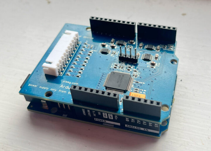
PiEEG has launched the ardEEG shield specially designed for the Arduino UNO R4 WiFi and capable of measuring biosignals such as those used in electroencephalography (EEG), electromyography (EMG), and electrocardiography (ECG).
PiEEG, led by Ildar Rakhmatulin, Research Associate at Heriot-Watt University in Edinburgh, launched the PiEEG shield for Raspberry Pi to enable brain-computer interfaces last year, and now the company has been working on the equivalent design for Arduino with the ardEEG shield equipped with eight channel taking input from wet or dry electrodes.
ardEEG Shield connected to Arduino UNO R4
ardEEG shield key features and specifications
ADC – Texas Instruments ADS1299 Analog-to-Digital Converter for biopotential measurements
8 channels for connecting wet or dry electrodes (Electrodes are positioned according to the International 10-20 system)
Host interface – Arduino headers with SPI used for data transfer with a frequency from 250 SPS to 16 kSPS and a resolution of 24 bits per channel
Programmable signal gain – 1, 2, 4, 6, 8, 12, 24
Ability to measure impedance
Power Supply + Safety – The device must operate only from a battery – 5 V. Complete isolation from the mains power is required.! The device MUST not be connected to any kind of mains power, via USB or otherwise.
Dimensions – Arduino UNO shield
Arduino UNO R4 WiFi with ardEEG shield connected to electrodes and power bank
The ardEEG shield is not a medical device and, as such, has not been certified by any government regulatory agency, so it’s better suited to the education and research markets although users can still create their own brain-computer interface projects for example to control robotic arm manipulation or for health monitoring.
PiEEG provides an Arduino sketch to read data from the electrodes plus a Python program for signal processing and visualization. Some examples include chewing and blinking and EEG signals monitoring, You’ll find everything to get started on GitHub. The video below also shows a short demo of the solution.
PiEEG sells the ardEEG shield on Elecrow for $240, but that does not include any electrodes so you’d have to bring your own or spend another $290 for the Cap EEG kit that you can place on the head of the subject. Additional details may also be found on the product page.
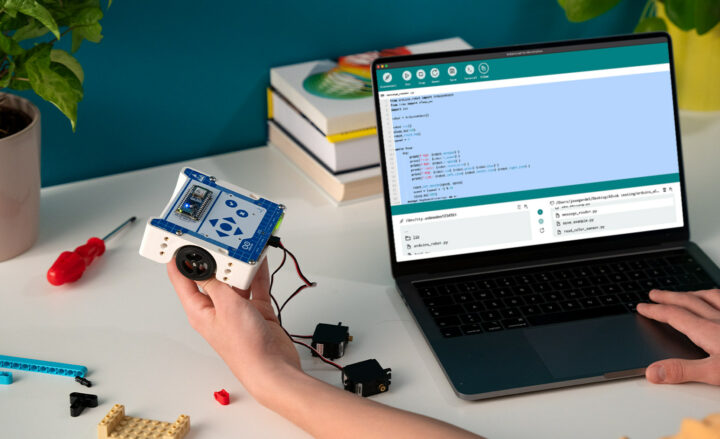
Arduino Education’s Arduino Alvik is a 3-wheel educational robot that was initially unveiled at the Bett 2024 show in London and designed to teach robotics, programming, and other STEAM subjects.
The robot is based on an Arduino Nano ESP32 board and comes with a set of nineteen lessons designed by Arduino Education’s team in collaboration with teachers so that students can learn the basics of IoT, get started with MicroPython, and get themselves familiar with various physics and engineering conc
Arduino Education’s Arduino Alvik is a 3-wheel educational robot that was initially unveiled at the Bett 2024 show in London and designed to teach robotics, programming, and other STEAM subjects.
The robot is based on an Arduino Nano ESP32 board and comes with a set of nineteen lessons designed by Arduino Education’s team in collaboration with teachers so that students can learn the basics of IoT, get started with MicroPython, and get themselves familiar with various physics and engineering concepts.
The company has yet to provide the full specifications for the Alvik robot, but here’s what we know at this stage:
Sensors – “High-quality sensors” that include a ToF ranging sensor, line-following sensors, a 6-axis accelerometer & gyroscope, a proximity sensor, and color sensors.
Expansion
2x Grove I2C connectors
2x Qwiic connectors
6-pin servo motor header for up to 2x micro servos (as shown in the photo above)
Misc
Capacitive touch buttons (D-Pad, OK, cancel)
On/off switch
Compatible with LEGO Technic and M3 screws
3D printing and laser cutting design-compatible
Power Supply – Rechargeable battery rechargeable through USB-C port on Arduino Nano ESP32
Arduino Education currently supports MicroPython programming, but work is being done to bring block-based programming and Arduino C lessons to the Arduino Alvik robot. The kit is suitable for primary school students up to advanced learners with lessons covering interactive game design, IoT, and AI projects. Besides the MicroPython lessons, more details may also be found on the documentation website.
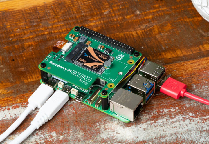
The official Raspberry Pi M.2 HAT+ is finally out for $12. The add-on board allows users to connect M.2 M-key peripherals, mainly NVMe SSDs, but also AI accelerators, to their Raspberry Pi 5 leveraging the PCIe connector on the(relatively) new SBC.
We have to stress “official” because it’s been possible to do the exact same thing with third-party boards from PineBerry (now PineBoards), Waveshare, Pimoroni, and Geekworm for about half a year. I also had the opportunity to review the GEEKWORM X100
The official Raspberry Pi M.2 HAT+ is finally out for $12. The add-on board allows users to connect M.2 M-key peripherals, mainly NVMe SSDs, but also AI accelerators, to their Raspberry Pi 5 leveraging the PCIe connector on the(relatively) new SBC.
Single-lane PCIe 2.0 interface (500 MB/s peak transfer rate) routed via Raspberry Pi PCIe FFC connector. (Note: PCIe 3.0 should also work fine on most Raspberry Pi 5 boards up to 800MB/s+, but this is not officially guaranteed).
Supplies up to 3A to connected M.2 devices
Expansion – 40-pin female/male header to extend the Raspberry Pi 5 GPIO header
The official Raspberry Pi M.2 HAT+ (M Key) board ships with a ribbon cable a 16mm GPIO stacking header, four threaded spacers, eight screws, and a knurled double-flanged drive attachment screw to secure and support the M.2 peripheral. The installation is straightforward, and you should make sure you have the latest firmware.
Raspberry Pi M2 HAT+ with 256GB NVMe SSD mounted on Raspberry Pi 5
Those commands may not be necessary if you have purchased a Raspberry Pi 5 recently, but in any case, they won’t hurt:
Great! But what took so long? Raspberry Pi explains they wanted to finalize the specifications of the 16-pin FFC connector and the new HAT+ form factor (preview for both released in December 2023), as there were still a few unresolved questions related to two “spare” pins initially carrying I2C signals, but finally used for power enable and board detect/wake signal. Some utilities (EEPROM utils) also had to be updated, and they tested a wide range of NVMe drives and other peripherals to investigate and solve various issues we found. They even got one SSD manufacturer to develop a fix for one of their SSDs (sadly and unsurprisingly they won’t say who).
Anyway, the good news is that the Raspberry Pi M.2 HAT+ Key M is now available from resellers for $12 plus taxes and shipping. Another somewhat related good news is that booting is now supported by the firmware on some HAT+ boards with a PCIe switch. This does not apply to the new M.2 HAT+ we’ve covered today, but several HAT with multiple drives or multiple functions such as the Geekworm X1004 with two M.2 sockets based on ASMedia ASM1182e switch, should now be able to boot Raspberry Pi OS or any other compatible operating system provided the specific PCIe switch is supported by the firmware.
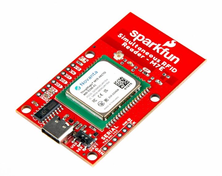
SparkFun has announced the M7E Hecto, a ‘simultaneous’ RFID reader in a compact form factor and high-performance capabilities. The RFID reader is powered by Jadak’s Hecto module (M7E-HECTO) from the ThingMagic series which offers a wide RF output range from 0 dBm to +27 dBm and reads up to 300 tags/second.
SparkFun M7E Hecto builds on the much older M6E Nano RFID reader, adding a USB-C port, increasing the read rate from 150 tags/second, and reducing power consumption. It supports an external a
SparkFun has announced the M7E Hecto, a ‘simultaneous’ RFID reader in a compact form factor and high-performance capabilities. The RFID reader is powered by Jadak’s Hecto module (M7E-HECTO) from the ThingMagic series which offers a wide RF output range from 0 dBm to +27 dBm and reads up to 300 tags/second.
SparkFun M7E Hecto builds on the much older M6E Nano RFID reader, adding a USB-C port, increasing the read rate from 150 tags/second, and reducing power consumption. It supports an external antenna (sold separately) which extends the scanning distance up to 16 ft (4.8m) from the 1 to 2 ft (0.3m – 0.6m) range supported by the onboard antenna.
It does come with a warning to ensure that personnel are not directly in the radiation beam of the antenna while they are within 21cm of the antenna (to adhere to FCC limits for long-term exposure to RF emissions).
The high read/write rates and extended range offered by the M7E Hecto can improve processing speed in applications such as asset tracking, inventory management, authentication, access control, and retail checkout.
ThingMagic M7E-HECTO
SparkFun M7E Hecto specifications:
RFID module – JADAK ThingMagic Hecto RAIN RFID module, supports EPCglobal Gen 2 (ISO 18000-6C) with a nominal backscatter rate of 250kbps
Separate read and write power levels, command adjustable from 0dBm to 27dBm in 0.01 dB steps
Read Rate – Up to 300 tags/sec to read 96-bit EPC format
Write Rate – 80ms for standard write of 96-bit EPC format
Power via USB-C
Supply Voltage – 3.3V to 5V
Supply Current – 1A max
Consumption @ 5V
Full: 0.665W
Minsave: 0.140W
Sleep: 0.080W
Operating Temperature Range – -40°C to 60°C (built-in thermal management)
Serial Interfaces – USB-C connector and 0.1”-spaced PTH header (3.3V logic), 2-way switch for interface selection
Enable and GPIO PTH pins
Antenna
Integrated PCB trace antenna (Default)
u.FL connector for external antenna connection
Dimensions – 60.96 mm x 35.56 mm
The M7E is supported by Jadak’s Universal Reader Assistant (only available on Windows) and the SparkFun Simultaneous RFID Tag Reader Arduino library which handles serial communication, byte manipulations, and CRC verifications. You can download the library through the Arduino library manager or SparkFun’s documentation website. The M7E Hecto is completely open-source and hardware schematics, production files, and documentation are hosted on GitHub.
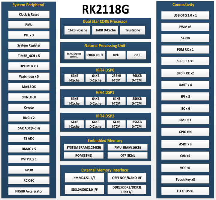
Rockchip RK2118G and RK2118M smart audio microcontrollers based on a dual-core Star-SE Armv8-M processor, an NPU for smart AI audio processor, three DSPs, 1024KB SRAM, optional DDR memory in package, and a range of peripherals.
I first noticed the RK2118M in slides from the Rockchip Developer Conference 2024 last March, but I did not have enough information for an article at the time. Things have now changed since I’ve just received a bunch of datasheets including the one for the RK2118G and RK2
Rockchip RK2118G and RK2118M smart audio microcontrollers based on a dual-core Star-SE Armv8-M processor, an NPU for smart AI audio processor, three DSPs, 1024KB SRAM, optional DDR memory in package, and a range of peripherals.
I first noticed the RK2118M in slides from the Rockchip Developer Conference 2024 last March, but I did not have enough information for an article at the time. Things have now changed since I’ve just received a bunch of datasheets including the one for the RK2118G and RK2118G microcontrollers, which look identical except for the DDR interface and optional built-in 64MB RAM for the RK2118G.
Rockchip Audio Roadmap 2023-2025 – Image source: BG5USN on X
The datasheets have only one reference to Arm with the string “Arm-V8M” and nothing else, and Cortex is not mentioned at all. But the slide above reveals the STAR-SE core looks to be an Arm Cortex-M33 core. We also learn the top frequencies for the “STAR-M33″/”STAR-SE” core (300MHz) and the DSPs (800MHz) neither are listed in the datasheet. The “STAR-SE” comes from Arm China, and while I could not find any detailed information about it, it’s also mentioned on Arm’s developer website for a vulnerability that also impacts Cortex-M33/M35/M55 cores which implies Arm is fine with it.
Rockchip RK2118G and RK2118M specifications:
CPU – Dual-core Star-SE (Cortex-M33) processor @ 300 MHzbased on Armv8M architecture with Thumb-2 support, FPU, MPU, Arm TrustZone, 16KB I-Cache and 16KB D-Cache
Neural Process Unit – 32x float point 16-bit MAC operations per cycle, 80KB internal buffer; supports TensorFlow, Caffe, Tflite, Pytorch, Onnx NN, Android NN, etc.
FIR/IIR Accelerator
Internal memory and storage
BootROM
1024KB System SRAM
16KB PMU SRAM
Optional integrated DDR memory, for example, 512 Mbit (64MB) DDR in RK2118G only
External memory and storage
16-bit DDR2/DDR3/DDR3L up to 1024MB (RK2118G only)
SPI NOR/NAND flash
eMMC 4.51 flash
SD Card (SD 3.0, MMC ver 4.51, SDIO 3.0 protocol)
Display Interface
RGB888/RGB565 source data format
RGB888/RGB565/RGB666 display data format
i8080 MCU serial interface up to 480×480 resolution
Audio
8x SAI components (I2S, PCM, TDM)
5-wire PDM interface for up to 8x mono microphones with 16 to 24-bit sample resolution
Temperature Range (Tj) – -40 to +125°C (in RK2118G datasheet, shown as TBD in RK2118M datasheet, and 0 to 80 for RK2118 in the slide above…)
Certifications – AEQ-100 Grade 3 expected in Q4 2024
Rockchip RK2118M block diagram
As one would expect, there’s nothing about software in the datasheet, but the slide lists an unnamed RTOS and RK_Studio support. It’s unclear what the latter is, but I would suspect it might be an IDE developed by Rockchip. I could also find the RK2118 mentioned in the same rknn-toolkit2 framework used by AI SoCs from the company such as RK3568 or RK3588.
It’s not Rockchip’s first venture into microcontrollers, but the company has not exactly been successful in this specific market in the past, as for instance, the Rockchip RKi6000 low-power WiFi microcontroller does not seem to have even come to market, and I’ve seldom seen the company’s RKNano microcontrollers in products or boards. We’ll see how it goes with the new RK2118 series.
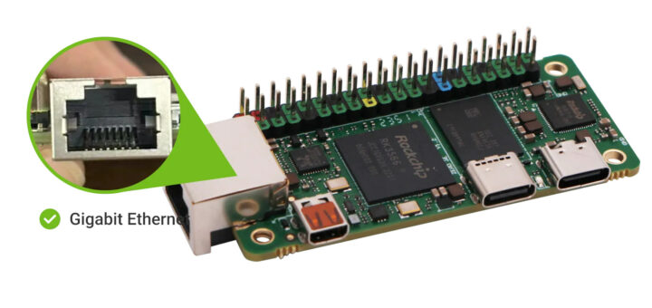
Last December, we wrote about the Rockchip RK3566-powered Radxa Zero 3W WiFi 6 SBC and noted that the Radxa Zero 3E with gigabit Ethernet and optional PoE supports would be coming soon with about the same dimensions as the Raspberry Pi Zero 2 W. “Soon” is now as the Radxa Zero 3E is now available on Aliexpress or Amazon with RAM capacities from 1GB to 8GB LPDDR4.
The small SBC also comes with optional eMMC flash up to 64GB, a microSD card slot for storage, a micro HDMI video output port, a MIPI
Last December, we wrote about the Rockchip RK3566-powered Radxa Zero 3W WiFi 6 SBC and noted that the Radxa Zero 3E with gigabit Ethernet and optional PoE supports would be coming soon with about the same dimensions as the Raspberry Pi Zero 2 W. “Soon” is now as the Radxa Zero 3E is now available on Aliexpress or Amazon with RAM capacities from 1GB to 8GB LPDDR4.
The small SBC also comes with optional eMMC flash up to 64GB, a microSD card slot for storage, a micro HDMI video output port, a MIPI CSI connector compatible with Raspberry Pi Camera V1 and V2, two USB-C ports, and a 40-pin GPIO header for expansion.
CPU – Quad-core Arm Cortex-A55 processor @ 1.6 GHz
GPU – Arm Mali G52-2EE GPU with support for OpenGL ES 1.1/2.0/3.2, Vulkan 1.1, OpenCL 2.0
NPU – 0.8 TOPS AI accelerator
VPU – 4Kp60 H.265/H.264/VP9 video decoding, 1080p100f H.265/H.264 video encoding
System Memory – 1GB, 2GB, 4GB, or 8GB LPDDR4
Storage
Optional 8GB, 16GB, 32GB, or 64GB eMMC 5.1 flash (Note: flash module is only available on the Radxa Zero 3W board, not the 3E variant)
MicroSD card slot (SDR104 capable)
Video Output – Micro HDMI port up to 1080p60 (Not sure why 4Kp60 is not listed since the processor supports it)
Camera – 4-lane MIPI CSI connector with support for Raspberry Pi Camera V1.3 (OV5647) and Raspberry Pi Camera V2 (IMX219).
Networking – Gigabit Ethernet RJ45 port via RTL8211F-CG transceiver; optional PoE support through HAT expansion board
USB – 1x USB 3.0 Type-C host port, 1x USB 2.0 Type-C OTG port
Expansion – Optional 40-pin color-coded GPIO header with up to 28x GPIO, 5x UART, 1x SPI, 2x I2C, PCM/I2S, 6x PWM, 5V, 3.3V, and GND
Misc – MaskROM button
Power Supply
5V/2A (recommended) via USB-C OTG port
Optional PoE support
Dimensions – 65 x 30mm (72 x 30mm when taking the RJ45 jack into account)
Radxa Zero 3E ports descriptionROCK Zero 3E Block Diagram
Radxa officially supports an image with Debian 11 using XFCE desktop environment, but Ubuntu XFCE and Ubuntu CLI images are also available and “provided as-is except for critical issues”. You’ll find schematics, OS images, and other resources to get started on the documentation website.
Radxa just launched its Aliexpress store and the Radxa Zero 3E is in stock with either 2GB or 4GB RAM there for respectively $20.97 and $30.97 plus shipping, while the 1GB RAM version is in stock on Amazon for $16. Sadly the Radxa 3E PoE HAT is not sold on either platform, but you can still get it from Arace for $9.99, or wait a few more weeks…
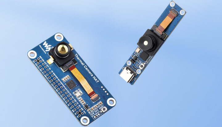
The Waveshare Thermal Imaging Camera module comes in two variants, namely the Thermal-45/90 Camera Raspberry Pi HAT and Thermal-45/90 USB Camera. The main difference between the two is that the HAT is designed to be attached to a Raspberry Pi, Pi Zero, or any other SBC that features a Pi-compatible pin layout like the Sipeed Longan Pi3H, Banana Pi BPI-M4, Radxa Zero 3W SBC, and others. On the other hand, the USB module can be connected to any PC, Android, or other device with a USB connection.
T
The Waveshare Thermal Imaging Camera module comes in two variants, namely the Thermal-45/90 Camera Raspberry Pi HAT and Thermal-45/90 USB Camera. The main difference between the two is that the HAT is designed to be attached to a Raspberry Pi, Pi Zero, or any other SBC that features a Pi-compatible pin layout like the Sipeed Longan Pi3H,Banana Pi BPI-M4, Radxa Zero 3W SBC, and others. On the other hand, the USB module can be connected to any PC, Android, or other device with a USB connection.
The camera features a shutterless design, which is why it can produce a thermal imaging video stream output of up to 25 frames per second (FPS). Additionally, Waveshare offers options for different fields of view (FOV) – a basic version with a 45° FOV and a wide-angle version with a 90° FOV, making it suitable for applications like IR thermometers, industrial temperature control, security & safety, intruder/motion detection, and more.
Waveshare Thermal Imaging Camera specifications:
Thermal image processor – MI48x3 with SenXor Bus, I2C, SPI, and USB Interface
Thermal camera module – MI0801 with Radiometric output, and Screw-type mount
Video stream – Up to 25FPS (Max) thermal imaging video stream output
Measuring accuracy – ±2°C (ambient temp. 10~70°C)
Operating voltage – 5V
Operating current – 61mA @ 5V
Temperature specs
Operating temperature: -20 to 85°C
Target temperature: -20 to 400°C
Dimensions
Thermal Camera HAT / Thermal-90 Camera HAT – 65.0×30.5mm
Thermal USB Camera / Thermal-90 USB Camera – 62.0×13.0mm
The camera HAT communicates with the Raspberry Pi using both I2C and SPI connections. I2C is utilized to configure the camera’s settings and registers, while SPI efficiently transfers the captured thermal data to the Raspberry Pi for processing and display.
HAT module connected to Raspberry Pi 4 (left) and USB module connected to PC (center) and Android (left)
Waveshare provides software packages for its Thermal Camera HAT and Thermal USB Camera modules for Windows, Android, Raspberry Pi (including Pi 5), and other Linux systems to capture, visualize, and analyze thermal data. The software packages along with the camera schematics, demo code, and datasheets for the MI48x3 Thermal image processor and Thermal camera module MI0801 can all be found on the Waveshare’s wiki.
The Waveshare Thermal Camera HAT and Thermal USB Camera modules are available on Amazon for $149.99 and $139.99 respectively with shipping included, at least to the US. Alternatively, the Thermal Camera HAT and USB module can be purchased on Aliexpress for $126.29 with free shipping, or directly on the Waveshare store for $119.99 plus shipping.
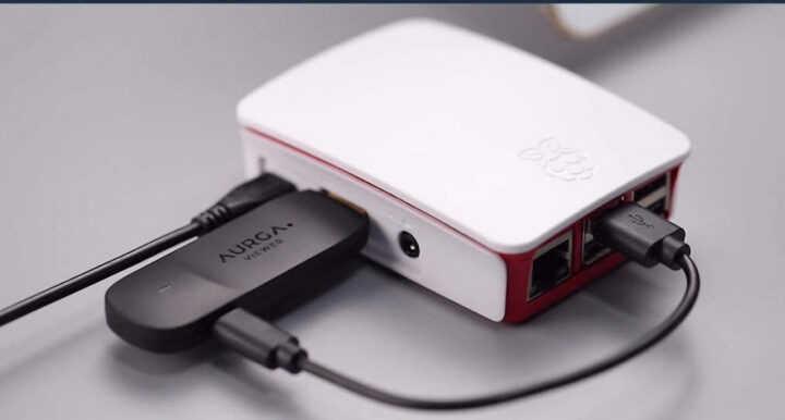
The AURGA viewer is an HDMI and USB dongle with WiFi and Bluetooth connectivity that plugs into any system with HDMI output and can convert any smartphone, tablet, or laptop with a touchscreen display into a KVM solution by sending video data, as well as keyboard and mouse events wirelessly.
We’ve recently written about Openterface Mini-KVM KVM-over-USB device that allows users to use their laptop to control another device with HDMI output locally without any additional display, keyboard, and mo
The AURGA viewer is an HDMI and USB dongle with WiFi and Bluetooth connectivity that plugs into any system with HDMI output and can convert any smartphone, tablet, or laptop with a touchscreen display into a KVM solution by sending video data, as well as keyboard and mouse events wirelessly.
We’ve recently written about Openterface Mini-KVM KVM-over-USB device that allows users to use their laptop to control another device with HDMI output locally without any additional display, keyboard, and mouse. But I’ve just been informed the AURGA Viewer, launched in 2022 on Kickstarter, can do something similar wirelessly.
AURGA Viewer specifications and features:
SoC – Allwinner S3 Cortex-A7 processor with 128MB DDR3
HDMI input – Male HDMI port with Toshiba TC35874x HDMI to MIPI CSI-2 bridge internally (See comments section); Works with VGA, mini HDMI, micro HDMI, etc… using adapters
Wireless – Broadcom BCM4345C5 SDIO 802.11AC WiFi 5 and Bluetooth 5 chip.
USB – USB port for power and data
Supported features
Wireless video streaming (1920x1080p 60Hz/48K Audio)
Mouse
Keyboard
Touch screen
Digitizer pen on phone/tablet
Stream wirelessly or through USB
Compatible devices (basically anything hardware with video output and USB)
Computer/Laptop
SBCs such as Raspberry Pi, Jetson Nano, Orange Pi, Banana Pi, Rock Pi
Gaming consoles such as PS3/PS4/PS5/Xbox Series/Wii U/Nintendo Switch
Mini PCs
Camera/DSLR
TV boxes etc..
Dimensions – 79.4 x 26 x 11mm
Weight – 14.5 grams
The company provides software for the host device running on Windows 64-bit, iOS, macOS, and Linux 64-bit Arm/x86 which you’ll find on the Download page. Note that most versions were updated last month (April 2024), but the Linux version is older (July 2023) and may not work as well.
The product may have been introduced about two years ago, but the company does a poor job of explaining how it all works… But the way I understand it, the target device views the AURGA Viewer as an HDMI display and USB mouse and keyboard, while the host runs the software to receive video and HID events over WiFi (and maybe Bluetooth), so the touchscreen display of the device is used as a monitor, keyboard, and mouse. The best is to watch one of the videos such as the one embedded below with an x86 motherboard with the AURGA Viewer controlled wirelessly from an iPad to install Windows. No need for an extra display, a mouse, and a keyboard, since everything is handled on the iPad.
It can also fully work with a laptop (without touchscreen) taking into account the trackpad and keyboard instead of the the touchscreen of a smartphone or tablet.
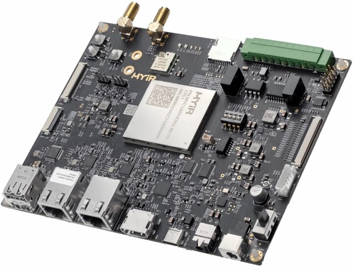
We have covered announcements about early NXP i.MX 93-based system-on-modules such as the ADLINK OSM-IMX93 and Ka-Ro Electronics’ QS93, as well as products integrating the higher-end NXP i.MX 95 processor such as the Toradex Titan Evaluation kit. Three additional NXP i.MX 93 SoMs from Variscite, Dart, and Compulab are now available.
Targeted at industrial, IoT, and automotive applications, the NXP i.MX 93 features a 64-bit dual-core Arm Cortex-A55 application processor running at up to 1.7GHz an
Targeted at industrial, IoT, and automotive applications, the NXP i.MX 93 features a 64-bit dual-core Arm Cortex-A55 application processor running at up to 1.7GHz and a Cortex-M33 co-processor running at up to 250MHz. It integrates an Arm Ethos-U65 microNPU, providing up to 0.5TOPS of computing power, and supports EdgeLock secure enclave, NXP’s hardware-based security subsystem. The heterogeneous multicore processing architecture allows the device to run Linux on the main core and a real-time operating system on the Cortex-M33 core.
The processor is designed for cost-effective and energy-efficient machine learning applications. It supports LVDS, MIPI-DS, and parallel RGB display protocols for industrial and non-industrial uses. It is also compatible with Linux, FreeRTOS, Greenhills, QNX, and VxWorks.
MYC-LMX9X System-on-Module
MYIR MYD-LMX9X development board
MYIR Tech’s MYC-LMX9X system-on-module is one of the most compact NXP i.MX 93 modules, at only 37mm by 39mm. It comes with 1 or 2GB LPDDR4 RAM, 8GB of eMMC storage, 32Kbit EEPROM, and an onboard power management IC (PMIC). The 218-pin expansion interface offers several connectivity options, including 2x USB 2.0, 3x SD/SDIO 3.01, 2x Gigabit Ethernet, and 2x CAN-FD interfaces.
MYIR MYD-LMX9X block diagram
The MYC-LMX9X is bound for applications in sectors such as healthcare equipment, human-machine interfaces, motion control, EV charging stations, and engineering machinery. It supports the Linux 6.1 operating system. The system-on-module is currently available in two SKUs on MYIR’s website, priced at $43 and $49 respectively. The development board comes with a USB to TTL cable, a 12V/2A Power adapter, and a quick start guide, and is available for $105 and $115.
DART-MX93 “DART Pin2Pin” System-on-Module
DART-MX93 SoM
Variscite’s DART-MX93 is the newest addition to its DART Pin2Pin family. It is described as a “rugged, cost-optimized solution for machine learning on edge devices for markets like industrial, IoT, smart devices, and wearables.” Carrier boards can be reused for all members of the DART Pin2Pin family, offering future-proofing and seamless scalability.
It measures 55 x 30mm – about half the size of a bank card – and integrates 2x camera interfaces (CSI2, ISI), 2x CAN bus, 2x GbE, audio in/out, 2x USB, Wi-Fi 6 dual-band 802.11 ax/ac/a/b/g/n with optional 802.15.4 and BT/BLE 5.3, in the industrial temperature grade of -40 to 85𝆩C. It supports Linux, Android, and FreeRTOS operating systems.
DART MX93 development board
The DART-MX93 is currently only available to Variscite’s alpha customers in production quantities at $39 per unit and the public release is said to be “coming soon.” Evaluation kits are also available, including the scalable VAR-DT8MCustomBoard and an optional LVDS display with a touch panel. More information is available on the product page.
MCM-iMX93 System-on-Module
Compulab MCM-IMX93 carrier board
Compulab’s MCM-iMX93 system-on-module comes in a solderable QFN form factor and is the smallest module in this list, measuring only 30 x 30 x 3 mm and weighing 5g. The SoM’s compact form factor makes it suitable for portable and space-tight applications. It is also designed to be resistant to shocks and vibrations.
It offers up to 2GB LPDDR4 RAM and 64GB eMMC flash. It features 2x GbE ports, three display interfaces (DSI, LVDS, and RGB), an externally powered real-time clock, 2x SD/SDIO, 2x CAN, 2x USB 2.0, 8x UART, 4x ADC, 6x PWM, and up to 80x GPIO. It runs Yocto Linux, Debian Linux, and RTOS, and supports over-the-air updates via Mender.
MCM-iMX93 System on Module Block Diagram
The module is available from $32 for bulk orders and the evaluation kit is priced at a base price of $245. You can find more details and ordering information on the company’s website.
Linus Torvalds has just announced the release of Linux 6.9 on LKML:
So Thorsten is still reporting a few regression fixes that haven’t made it to me yet, but none of them look big or worrisome enough to delay the release for another week. We’ll have to backport them when they get resolved and hit upstream.
So 6.9 is now out, and last week has looked quite stable (and the whole release has felt pretty normal). Below is the shortlog for the last week, with the changes mostly being dominated by som
Linus Torvalds has just announced the release of Linux 6.9 on LKML:
So Thorsten is still reporting a few regression fixes that haven’t made it to me yet, but none of them look big or worrisome enough to delay the release for another week. We’ll have to backport them when they get resolved and hit upstream.
So 6.9 is now out, and last week has looked quite stable (and the whole release has felt pretty normal). Below is the shortlog for the last week, with the changes mostly being dominated by some driver updates (gpu and networking being the big ones, but “big” is still pretty small, and there’s various other driver noise in there too).
Outside of drivers, it’s some filesystem fixes (bcachefs still stands out, but ksmbd shows up too), some late selftest fixes, and some core networking fixes.
And I now have a more powerful arm64 machine (thanks to Ampere), so the last week I’ve been doing almost as many arm64 builds as I have x86-64, and that should obviously continue during the upcoming merge window too. The M2 laptop I have has been more of a “test builds weekly” rather than “continuously”.
Not that I really expect that to really show any issues – the laptop builds never did – but I feel happier having a bit more coverage.
Anyway, please keep testing, and obviously this means that tomorrow the merge window for 6.10 opens. I already have a few dozen pull requests pending, I appreciate the early birds,
Linus
Released about two months ago, Linux 6.8 brought us a new experimental Intel Xe drm driver that aims to replace the legacy i915 driver for new Intel GPUs, the ability for the zswap subsystem to force cold pages out to (real) swap when memory gets tight, rust support for the creation of network PHY drivers, better cache efficiency for networking thanks to the reorganization of data structures, and many more changes. Linux 6.8 also happens to be the default kernel in the just-released Ubuntu 24.04 OS.
Main changes in Linux 6.9
Some notable changes for the new Linux 6.9 kernel include:
Added support for Intel Flexible Return and Event Delivery (FRED) which aims to improve low-level event delivery and allows for simpler and more reliable code; See documentation commit for additional details
Added support for running AMD Secure Nested Paging (SNP) guests (see PDF documentation), part of AMD’s confidential-computing solution. However, full support requires KVM changes which have been deferred until Linux 6.10.
Mitigations for the latest x86 hardware vulnerability “Register File Data Sampling” (RFDS) impacting Intel Atom CPUs have been merged. More details may be found in this documentation commit.
Linux 6.9 can make use of GCC’s named address spaces feature to optimize access to per-CPU data.
Initial support for FUSE passthrough has been merged. This feature allows I/O to files served by a user-space FUSE server to be handled directly by the kernel resluting in significant performance increases under some conditions. The passthrough mode only supports privileged servers in Linux 6.9.
Linux 6.9 changelog for the Arm architecture
The Rust language is now supported on 64-bit Arm processors.
It is now possible to run 64-bit Arm CPUs in LPA2 mode, which sets up a 52-bit virtual address space.
Clock driver – Fix clock listing Oops on Amlogic axg
Amlogic T7 – GPIO and IRQ drivers
Amlogic ARM64 DT changes for Linux 6.9:
Add reset controller for Amlogic C3
Set initial rate for the NPU on Amlogic G12 SoCs
Set initial clocks for USB on Amlogic A1
Initialize Amlogic AXG SoC capacitance
Drop unstable remark on Amlogic Bindings
Add all Amlogic maintainers/reviewers on Amlogic SoCs bindings
Cleanups – T7 whitespaces, underscore in names
New device – Freebox Pop Player (IPTV Set-To-Box from Free French internet provider based on Amlogic Meson G12A S905X2)
Samsung
Extend Exynos PMU (Power Management Unit) driver being also the syscon to main system controller registers block, to support Google GS101. The Google GS101 has PMU registers protected and writing is available only via SMC. The Exynos PMU will register its own custom regmap for such case of mixed MMIO+SMC.
Rework Samsung watchdog driver to get the regmap to PMU block not via syscon API, but from the Exynos PMU driver. This is necessary for the watchdog driver to work on Google GS101.
DTS Arm changes for Linux 6.9
Disable thermal polling by Linux in Eynos5422 Odroid XU3 boards, because drivers implement proper dynamic trip points management.
Mark crosc-ec-spi in Peach Pi and Peach Pit as wake-up source, to reflect the hardware capabilities.
Samsung P4 Note (Exynos4412): add accelerometer.
Samsung Galaxy Tab (Exynos5420)
Reduce available RAM to avoid conflict with TrustZone.
Add WiFi on MMC.
Samsung DTS ARM64 changes
Mostly work around Google GS101 SoC and Pixel phone (Oriole) adding support for:
Multi Core Timer (MCT) clocksource.
Several clock controllers (DTS and DT bindings) and use new clocks in several other device nodes.
More serial-interface instances: USI8 and USI12 with I2C.
Exynos850 – SPI and DMA controllers (PL330).
Defconfig changes – N/A
New Devices – N/A
Qualcomm
PHY driver – Qualcomm X1E80100 PCIe phy support, SM8550 PCIe1 PHY, SC7180 UFS PHY and SDM630 USB-C support
WiFi
Qualcomm (ath11k):
Support 6 GHz station power modes: Low Power Indoor (LPI), Standard Power) SP and Very Low Power (VLP)
QCA6390 & WCN6855: support 2 concurrent station interfaces
QCA2066 support
Qualcomm (ath12k):
Refactoring in preparation for Multi-Link Operation (MLO) support
1024 Block Ack window size support
firmware-2.bin support
support having multiple identical PCI devices (firmware needs to have ATH12K_FW_FEATURE_MULTI_QRTR_ID)
QCN9274: support split-PHY devices
WCN7850: enable Power Save Mode in station mode
WCN7850: P2P support
ARM32 DTS updates
MSM8226 – SAW and ACC nodes are introduced to enable SMP support. Watchdog definition is also added, and all nodes are sorted and cleaned
up. rmtfs memory is defined on HTC One Mini 2, vibrator support is added to LG G Watch R, touch keycodes are defined for Samsung Galaxy Tab 4. The Samsung Galaxy Tab 4 DeviceTree is refactored to allow more variants to be introduced easily.
The SAW nodes across APQ8064, IPQ8064, MSM8960 and MSM8974 are updated based on recent work on the binding and driver.
IPQ8064 – SAW nodes are cleaned up, and unused reset-names is dropped from DWC3.
MSM8960 – GSBI3 and the I2C bus therein is introduced, in order to introduce touchscreen support on the Samsung Galaxy Express SGH-I437. gpio-keys are introduced on the same.
MSM8974 – The QFPROM register size is corrected. The order of the clocks in the SDX65 DWC3 node is corrected to match the binding.
The mach-qcom Kconfig options are cleaned up, to avoid unnecessary per-platform options.
Arm64 DTS updates for Linux 6.9
Snapdragon X Elite – Audio and compute remoteprocs, IPCC, PCIe, AOSS QMP, SMP2P, TCSR, USB, display, audio, and soundwire support is introduced, and enabled across the CRD and QCP devices.
SM8650 – PCIe controllers are moved to GIC-ITS and msi-map-mask is defined. Missing qlink-logging reserved-memory region is added for the modem remoteproc. FastRPC compute contexts are marked dma-coherent. Audio, USB Type-C and PM8010 support is introduced across MTP and QRD devices.
GPU cooling devices are hooked up across MSM8916, MSM8939, SC8180X, SDM630, SDM845, SM6115, SM8150, SM8250, SM8350, and SM8550.
UFS PHY clocks are corrected across MSM8996, MSM8998, SC8180X, SC8280XP, SDM845, SM6115, SM6125, SM8150, SM8250, SM8350, SM8550, and SM8650.
PCI MSI interrupts are wired up across SM8150, SM8250, SM8350, SM8450, SM8550, SM8650, SC7280, and SC8180X
IPQ6018 – QUP5 I2C, tsens sand thermal zones are defined.
The Inline Crypto Engine (ICE) is enabled for IPQ9574.
MSM8953 – The GPU and its IOMMU is introduced, the reset for the display subsystem is also wired up.
VLS CLAMP registers are specified for USB3 PHYs on MSM8998, QCM2290, and SM6115.
QRB4210 RB2 – USB Type-C port management is enabled.
SA8295P ADP – The MAX20411 regulator powering the GPU rails is introduced and the GPU is enabled. The first PCI instance on SA8540P Ride is disabled for now, as a fix for the interrupt storm produced here has not been presented.
SA8775P – The firmware memory map has changed and is updated. Safety IRQ is added to the Ethernet controller.
SC7180 – UFS support is introduced and the cros-ec-spi is marked as wakeup source.
SC7280 – Capacity and DPC properties are added, cryptobam definition is improved to work in more firmware environments, more Chrome-specific properties are moved out from main dtsi, and cros-ec-spi is maked as a wakeup source. Slimbus definition is added to the platform.
A missing reserved-memory range is added to Fairphone FP5, PMIC GLINK and Venus are enabled. LEDs are introduced and voltage settings corrected on the QCM6490 IDP, and RB3gen2 sees the same voltage changes and GCC protected clocks are introduced to make the board boot properly.
RPMh sleep stats and a variety of cleanups and fixes are introduced for SC8180X.
SC8280XP – The additional tsens instances are introduced. Camera Subsystem and Camera Control Interface (CCI) are added. PMIC die-temp vadc channels are introduced on the CRD, to allow ADC channels to be tied to the shared PMIC temp-alarms, to actually report temperature.
SDM630 – USB QMP PHY support is introduced and enabled on the Inforce IFC6560 board. On the various Sony Xperia XA2 variants WLED is enabled and configured.
SM6350 – Display subsystem interconnects and tsens-based thermal zones are added.
SM7125 – UFS support is added.
Fairphone FP4 (SM7225) – Display and GPU are enabled, and firmware paths are corrected.
SM8150 – PCIe controller definitions are corrected.
SM8550 – As with SM8650, the SM8550 the fastrpc compute contexts are marked dm-coherent, and PCIe controllers are moved to use GIC-ITS. The UFS controller frequency definition is moved to the generic opp-table. Touchscreen is enabled on the QRD device.
Variety of smaller cleanups and corrections to match DeviceTree bindings and style guidelines are introduced across the various files.
Arm64 defconfig updates
Enable the Qualcomm PBS driver to resolve the dependency from the Light Pulse Generator (LED-driver) on modern Qualcomm platforms. Enable the X1E multimedia clock controllers, to provide clocks for the various multimedia blocks. Enable Global clock controller and interconnect drivers for the QDU1000/QRU1000 platforms.
Enable the audio drivers and the Goodi Berlin touchscreen driver, used on SM8650 QRD.
Enable the MAX20411 regulator driver drive the GPU rail on SA8295P.
Mark the Qualcomm interconnect providers that feeds UART instances as builtin, to ensure the console exists when userspace is launched.
New devices and boards
Samsung Galaxy Tab 4 10.1 LTE
Four variants of Samsung Galaxy Core Prime and Grand Prime, built on MSM8916
SM8550 (Snapdragon 8 Gen 2) Hardware Development Kit (HDK)
MediaTek
Added support for Mediatek MT7981B (Filogic 820) and MT7988A (Filogic 880) networking SoCs designed to be used in wireless routers, and similar to the already supported MT7986A (Filogic 830).
PHY driver – Mediatek MT8365 CSI phy driver
DMA engine – Yaml conversion for MediaTek High-Speed controller binding
Add support for Sound to MediaTek MT6357 CODEC
mt76 wifi driver:
mt7915: newer ADIE version support
mt7925: radio temperature sensor support
Defconfig updates
Arm Devicetree updates for Linux 6.9
Adds more support for the MediaTek MT8186 SoC’s Video and JPEG encoders
Adds MT7988 clocks
Enables wakeup support for the CrOS EC on SPI in all MediaTek Chromebooks
Performs some cleanups and includes some spare fixes.
The Waveshare ESP32-S3-Matrix is a microcontroller development board designed for AIoT applications, featuring a larger 8×8 RGB LED matrix (64 LEDs) compared to the 5×5 RGB LED matrix (25 LEDs) on the ESP32-C3/ESP32 based “C3FH4 RGB” / “PICO D4 RGB” board. In addition to that the Waveshare board features two 10-headers for GPIOs, UART, and power signals, along with an integrated QMI8658C attitude sensor (9-axis IMU sensor), making it ideal for robotics and motion control projects.
Recently we ha
The Waveshare ESP32-S3-Matrix is a microcontroller development board designed for AIoT applications, featuring a larger 8×8 RGB LED matrix (64 LEDs) compared to the 5×5 RGB LED matrix (25 LEDs) on the ESP32-C3/ESP32 based “C3FH4 RGB” / “PICO D4 RGB” board. In addition to that the Waveshare board features two 10-headers for GPIOs, UART, and power signals, along with an integrated QMI8658C attitude sensor (9-axis IMU sensor), making it ideal for robotics and motion control projects.
Like other waveshare boards, the company provides a detailed specification diagram, making it easy to identify every major component of the board. This diagram also works as a troubleshooting guide, as you can now quickly pinpoint any faulty components using the diagram as a reference.
The company also provides a pinout diagram making it easy for you to get started with the board or add other peripherals to the board.
Regarding software support, the board can be programmed with ESP-IDF, Arduino IDE, and MicroPython, which are available from their respective websites. Additional documentation, such as the pinout diagram, installation guide, live example images, and links for all the resources can be found on their wiki page.
Oak Development Technologies has recently announced Lattice FeatherWing – An iCE40-based development board designed to be controlled by Adafruit Feather. Previously we wrote about the IcyBlue Feather V2, a standalone development built around a Lattice Semi iCE5LP4K FPGA. But this FeatherWing board is designed to add functionality to your existing Adafruit Feather board.
The Lattice FeatherWing expands your Adafruit Feather with a Lattice iCE5LP4K FPGA. It connects and gets programmed over SPI so
Oak Development Technologies has recently announced Lattice FeatherWing – An iCE40-based development board designed to be controlled by Adafruit Feather. Previously we wrote about the IcyBlue Feather V2, a standalone development built around a Lattice Semi iCE5LP4K FPGA. But this FeatherWing board is designed to add functionality to your existing Adafruit Feather board.
The Lattice FeatherWing expands your Adafruit Feather with a Lattice iCE5LP4K FPGA. It connects and gets programmed over SPI so you can use all the FPGA’s GPIO pins through the header blocks. There’s also a built-in RGB LED directly connected to the FPGA’s open-drain pins, for visual feedback.
Integrates two hardware I2C and SPI blocks for enhanced functionality
Supported I/O Standards – LVCMOS33, LVCMOS25, and LVCMOS18
Communication Blocks
2x I2C hard blocks
2x SPI hard blocks
Indicators – RGB LED as status indication (24 mA Current Drive)
Clock Management
One Phase-Locked Loop (PLL) for advanced clock management
Multiple on-chip oscillators for standalone operation
GPIO – 47 Accessible GPIOs
Form Factor – Adafruit Feather form factor
Like the previous IcyBlue Feather V2 board, this board is also compatible with open-source tools like IceStorm and proprietary software from Lattice Semiconductor, such as the Diamond Programmer.
Other than that not much information is available, but the company says all the previous examples on their GitHub repos will be compatible with this board. At the time of writing no such schematics or design files for the board are available, but they should be available in the future. you can get your hands on this unique development board at Oak Development Technologies Tindie store priced at $24.95.
Today, We will review the Cytron Maker Uno RP2040 development board combining the Arduino UNO form factor with the Raspberry Pi RP2040 microcontroller that makes it programmable with the Arduino IDE (C/C++), Micropython, or CircuitPython.
The board is suitable for both beginners and advanced users with a convenient port layout that includes a “Maker” connector plus six Grove connectors for sensor modules and a header for four servos besides the Arduino UNO headers. The board offers two power opt
Today, We will review the Cytron Maker Uno RP2040 development board combining the Arduino UNO form factor with the Raspberry Pi RP2040 microcontroller that makes it programmable with the Arduino IDE (C/C++), Micropython, or CircuitPython.
The board is suitable for both beginners and advanced users with a convenient port layout that includes a “Maker” connector plus six Grove connectors for sensor modules and a header for four servos besides the Arduino UNO headers. The board offers two power options: USB (5V) via the USB-C connector or a single-cell LiPo/Li-Ion battery via the LiPo connector.
Cytron Maker Uno RP2040 specifications
SoC – Raspberry Pi RP2040 dual-core Arm Cortex-M0+ processor @ up to 133 MHz with 264 KB SRAM
Storage – 2MB flash
USB – USB-C port for power and programming
Expansion
Arduino UNO headers for shields
6x Grove Ports (Digital I/O, PWM Output, UART, I2C, Analog Input)
1x Maker port compatible with Qwiic, STEMMA/QT, and Grove module (the latter via conversion cable)
12-pin header for 4x servos
Misc
16x Status LEDs for GPIO
1x Piezo Buzzer with mute switch
User programmable keypad
Reset button
Boot button
2x RGB LEDs (WS2812)
Power Supply
5V via USB-C port
Single-cell LiPo connector with built-in overcharge/discharge protection circuitry
Dimensions – 60.96 x 9.40 cm (Arduino UNO form factor)
Pinout diagram
Unboxing of the Cytron Maker Uno RP2040 kit
The Maker Uno RP2040 can be purchased as a standalone board, but we requested a few modules to make the review more interesting and received everything in a single package.
Our kit includes the Maker Uno RP2040 itself, four Grove to jumper cables, a USB-A to USB-C cable, a soil moisture sensor with one Grove cable, an HC-SR04 ultrasonic sensor with a Grove cable, a SG90 micro servo with accessories, a 0.96-inch I2C OLED display (128×64 resolution), and four silicon rubber feet.
Here’s a closer look at the top of the board…
… and the bottom side with the Raspberry Pi RP2040 microcontroller and a white area to let students write their names.
All modules are well-known off-the-shelf parts so we won’t go into details this time.
Getting started with the Maker Uno RP2040 board using the Arduino IDE
As mentioned in the introduction, the Maker Uno RP2040 can be powered with either a USB Type-C cable (5V) or a single-cell Li-Po/Li-Ion battery (3.7V). In this review, we will use a USB Type-C cable for power and to program the board with a laptop running Windows 11.
The Maker Uno RP2040 supports Arduino, Micropython, and CircuitPython programming, but in this review, we will be focusing on the former. So the first step is to download and install the Arduino IDE for your operating system. We used the latest version available at the time of the review, namely Arduino IDE 2.3.2 for Windows.
Arduino IDE configuration
We’ll be mostly following Cytron’s tutorial to work with the Cytron Maker UNO RP2040 using the Arduino IDE. Three steps are needed for the initial configuration.
Add Maker Uno RP2040 to the Arduino IDE.
Go to File->Preferences menu, and add the URL “https://github.com/earlephilhower/arduino-pico/releases/download/global/package_rp2040_index.json” in the “Additional Boards Manager URLs”
Select OK and search for “Uno RP2040” to install the board package.
Once installed, you will find the Maker Uno RP2040 board in the Arduino IDE. Just select it from Tools > Board > Raspberry Pi Pico/RP2040 > Cytron Maker Uno RP2040 or in the drop-down menu.
Enter Bootloader mode by connecting the Maker Uno RP2040 to your laptop. Press and hold the BOOT button and press RESET (just one press!) and a new drive named RPI-RP2 will appear in the File Manager.
Select the board and COM port
Select the Maker Uno RP2040 board from Tools > Board > Raspberry Pi Pico/RP2040 > Cytron Maker Uno RP2040
Select the COM port by going to Tools > Port (the first time the COM port will be “UF2_Board”). After uploading the sketch, the board will reset and the COM port will appear under a name such as “COM12”. Now we are ready to start coding.
Blinking some LEDs
Make sure the correct board and COM port are selected in the Arduino and copy the following code to blink two LEDs every 500ms:
/*
DESCRIPTION:
This example code will use Maker Uno RP2040 to light up any of two onboard GPIOs LEDs alternately.
For this code, GPIOs LED for GPO and GP1 pin are selected.
Each LED will be blinking every each 0.5 second alternately.

AUTHOR   : Cytron Technologies Sdn Bhd
WEBSITE  : www.cytron.io
EMAIL    : support@cytron.io
*/

 // Pin assignments for LEDs
const int ledPin1 = 0;
const int ledPin2 = 1;

void setup() {
  // initialize leds on GP0 and GP1 pins as output.
  pinMode(ledPin1, OUTPUT);
  pinMode(ledPin2, OUTPUT);
}

void loop() {
  // led GP0 is light up for 0.5s then turned off.
  digitalWrite(ledPin1, HIGH);
  delay(500);
  digitalWrite(ledPin1, LOW);
  delay(500);

  // led GP1 is light up for 0.5s then turned off.
  digitalWrite(ledPin2, HIGH);
  delay(500);
  digitalWrite(ledPin2, LOW);
  delay(500);
}
Select Verify to check the code compiles and then Upload the sketch to your Maker Uno RP2040 board.
Two LEDs should now be blinking on the board (connected to GP0 and GP1) alternating every 0.5 seconds. (Note GP2 is always on, and we can’t see GP1 clearly in the animated WebP file above but it’s blinking too).
Controlling the RGB LEDs
Here’s an Arduino sketch to cycle the colors of the two RGB LEDs on the board going to Red, Green, Blue, and off:
/*
DESCRIPTION:
This example code will use Maker Uno RP2040 to light up the on-board RGB leds.
The RGB LEDs will sequentially changing their colors individually.

AUTHOR   : Cytron Technologies Sdn Bhd
WEBSITE  : www.cytron.io
EMAIL    : support@cytron.io

REFERENCE:
Adafruit_NeoPixel library link:
https://github.com/adafruit/Adafruit_NeoPixel/tree/master

*/

#include <Adafruit_NeoPixel.h>

// Declare pin number of the Neopixel LED and the number of the LED
const int neoPin = 25;
const int numPixels = 2;

// Initialize the NeoPixel RGB LEDs on pin GP25
Adafruit_NeoPixel pixels(numPixels, neoPin, NEO_GRB + NEO_KHZ800);

void setup() {

  pixels.begin(); // Initialize NeoPixel library
  pixels.clear(); // Set all pixel colors to 'off'
  pixels.show();  // Send the updated pixel colors to the hardware.
}

void loop() {

  // pixels.Color() takes RGB values, from 0,0,0 up to 255,255,255
  // NeoPixels are numbered from 0 to (number of pixels - 1).

  pixels.setPixelColor(0, pixels.Color(200, 0, 0)); // Red
  pixels.setPixelColor(1, pixels.Color(200, 0, 200)); // Magenta
  pixels.show();   // Send the updated pixel colors to the hardware.
  delay(1000);

  pixels.setPixelColor(0, pixels.Color(0, 200, 0)); // Green
  pixels.setPixelColor(1, pixels.Color(200, 200, 0)); // Yellow
  pixels.show();   // Send the updated pixel colors to the hardware.
  delay(1000);

  pixels.setPixelColor(0, pixels.Color(0, 0, 200)); // Blue
  pixels.setPixelColor(1, pixels.Color(0, 200, 200)); // Cyan
  pixels.show();   // Send the updated pixel colors to the hardware.
  delay(1000);

  pixels.setPixelColor(0, pixels.Color(0, 0, 0)); // Black (turn off the LED)
  pixels.setPixelColor(1, pixels.Color(0, 0, 0)); // Black (turn off the LED)
  pixels.show();   // Send the updated pixel colors to the hardware.
  delay(1000);
}
Let’s now Upload the sketch to the maker Uno RP2040 board…
The RGB LEDs will change color and turn off in a loop as expected.
Controlling an LED with the user button
The Arduino sketch below turns on or off the LED connected to the GP1 pin when pressing the user button (GP2) on the Maker Uno RP2040 board:
/*
DESCRIPTION:
This example code will show how to use the User button on the Maker Uno RP2040 as an Input.
In this code, the button will be used to control an on-board LED.
If the button is pressed, the LED will light up for 0.5 second then turned off

AUTHOR  : Cytron Technologies Sdn Bhd
WEBSITE  : www.cytron.io
EMAIL    : support@cytron.io
*/

  // Declare pin assignments for LED and button.
const int ledPin1 = 8;
const int btn1 = 2;


void setup() {
  // initialize leds GP8 pins as output and the user button GP2 as input
  pinMode(ledPin1, OUTPUT);
  pinMode(btn1, INPUT_PULLUP);

}

void loop() {
  // check button 1 (GP2) is pressed
  if (!digitalRead(btn1)) {
    // led GP0 is light up for 0.5s then turned off.
    digitalWrite(ledPin1, HIGH);
    delay(500);
    digitalWrite(ledPin1, LOW);
  }

}
Buzzer testing
We’ll play some sound through the buzzer when pressing the user button (GP2) using this code:
/*
DESCRIPTION:
This example code will use the the buzzzer on the Maker Uno RP2040 to play the tones.
The User button also used in this code. Upon startup, a short melody will be played
and then the code will wait for the button press to play another set of short tones.

AUTHOR   : Cytron Technologies Sdn Bhd
WEBSITE  : www.cytron.io
EMAIL    : support@cytron.io
*/

// Declare pin assigment for buzzer and button
const int buzzerPin = 8;
const int btn1 = 2;

// Create an array of the melody note frequency with its corresponding duration for each note
int melody_note[10] = {659, 659, 0, 659, 0, 523, 659, 0, 784, 0}; // [E5, E5, REST, E5, REST, C5, E5, REST, G5]
int melody_duration[10] = {150, 150, 150, 150, 150, 150, 150, 150, 200, 150};

void setup(){
  // Initialize buzzer pin as output
  pinMode(buzzerPin, OUTPUT);

  // Initialize buttons
  pinMode(btn1, INPUT_PULLUP);

  // Play melody during start up
  play_melody(buzzerPin);
}

void loop(){
  // Check button 1 (GP2) is pressed
  if (!digitalRead(btn1)) {
    // Play tones
    tone(buzzerPin,262,100);
    delay(100);
    tone(buzzerPin,659,100);
    delay(100);
    tone(buzzerPin,784,100);
    delay(100);
    noTone(buzzerPin);
  }
}

void play_melody(int pin){
  for(int i=0; i<10; i++){
    if(melody_note[i] == 0){
      noTone(pin);
    }
    else{
     tone(pin, melody_note[i], 100);
    }
    delay(int(melody_duration[i]));
  }
}
After uploading the sketch, we should hear a short snippet of Mario Bros theme melody each time we press the user button
Arduino sketch to control a micro servo from the Maker Uno RP2040
We’ve only tested hardware built-in on the Maker Uno RP2040 board so far, but we’ll now start testing expansion capabilities by connecting an S90 micro servo to the GP14, +, and – pins of the SERVO header.
The Arduino sketch below will rotate the four servos from 0 degrees to 180 degrees and back in an infinite loop:
/*
DESCRIPTION:
This example code will use Maker UNO RP2040 to control four servo motors connected to the onboard servo ports.
The servo motor will sweep from 0° to 180° with an increment of 1° every 10 milliseconds.
Then  the servos moves back from 180 degrees to 0 degrees with a decrement of 1 degree every each 10 milliseconds.

AUTHOR   : Cytron Technologies Sdn Bhd
WEBSITE  : www.cytron.io
EMAIL    : support@cytron.io
*/

  // Include the servo library
#include <Servo.h>

  // Create servo objects for each servos
Servo servo1;
Servo servo2;
Servo servo3;
Servo servo4;

void setup() {

  // Attach each servo object to their corresponding pins
  servo1.attach(14);
  servo2.attach(15);
  servo3.attach(16);
  servo4.attach(17);
}

void loop() {

   // Move the servos from 0 degress to 180 degrees with with an increment of 1 degree per step
  for (int pos = 0; pos <= 180; pos += 1) {
  servo1.write(pos);     // Set Servo 1 position to 'pos' degrees
  servo2.write(pos);     // Set Servo 2 position to 'pos' degrees
  servo3.write(pos);     // Set Servo 3 position to 'pos' degrees
  servo4.write(pos);     // Set Servo 4 position to 'pos' degrees
  delay(10);  // Pause for 15 milliseconds to control the speed of servo movement
  }

   // Move the servos from 180 degress to 0 degrees with with a decrement of 1 degree per step
  for (int pos = 200; pos >= 0; pos -= 1) {
  servo1.write(pos);     // Set Servo 1 position to 'pos' degrees
  servo2.write(pos);     // Set Servo 2 position to 'pos' degrees
  servo3.write(pos);     // Set Servo 3 position to 'pos' degrees
  servo4.write(pos);     // Set Servo 4 position to 'pos' degrees
  delay(10);   // Pause for 15 milliseconds to control the speed of servo movement
  }
}

/*
NOTE:
This code is written for standard servo motors. If you are using  360 degree continous rotation servo,
the servo.write (pos) function behave differently than standard servo. It controls speed rather than position.
A value near 90 means no movement, 0 is full speed in one direction and  180 is full speed in other direction

*/
We only have one micro servo which we connected to GP14 (S1) and added a small flag for dramatic effect
The servo motor rotates smoothly from 0° to 180° in increments of 1° every 10 ms. When it reaches 180°, it reverses direction and moves back to 0° in increments of 1° every 10 ms.
Reading analog values from a soil moisture sensor
The Maker Uno RP2040 board comes with various Grove connectors with digital, analog, or I2C interfaces.
We’ll first test an analog connector (Grove 5) using a Maker soil moisture sensor to measure humidity in a glass of water.
There are dry, moist, and wet LEDS on the sensor module, but the following code will report the raw and voltage values from the A3 (GP29) pin in the serial monitor:
/*
DESCRIPTION:
This example code will use Maker Uno RP2040 to read the analog input from Maker Soil Module
and then show the result on serial monitor. This code also applicable to any analog sensor.

CONNECTION:

Grove 5 of Maker Uno RP2040 : Maker Soil Module
GP29 - OUT pin of the Maker Soil Module

AUTHOR   : Cytron Technologies Sdn Bhd
WEBSITE  : www.cytron.io
EMAIL    : support@cytron.io
*/

int sensorPin = 29;    // select the input pin for the potentiometer
int raw_value = 0;
float voltage_value = 0;

void setup() {
  // declare the sensorPin as an OUTPUT:
  pinMode(sensorPin, INPUT);
  Serial.begin(9600);
  // enable adc resolution to 12-bit (default 10-bit)
  analogReadResolution(12);
}

void loop() {

  // read the value from the sensor:
  raw_value = analogRead(sensorPin);
  // Convert the raw ADC value to voltage (3.3V is the board's voltage reference)
  voltage_value = (raw_value * 3.3) / 4095;

  Serial.print("Raw Value : ");
  Serial.println(raw_value);
  Serial.print("Voltage Value : ");
  Serial.println(voltage_value);
  Serial.println("---------------------------");

  delay(1000);
}
Once the sketch is running, we can open the Serial Monitor to check out the values updates in a loop every 1 seconds.
Reading digital values from an HC-SR04 ultrasonic sensor
While only two of the Grove connectors support analog, any of the 6 Grove connectors and the Maker port can be configured to take a digital sensor. In this review, we will be using an HC-SR04 ultrasonic sensor module connected to pins 20 (ECHO signal), 21 (TRIG signal), and 3.3V and GND of the Grove 6 connector on the Maker Uno RP2040 board in order to measure the distance to the Cytron retail box.
Here’s the Arduino sketch to measure the distance and output the value in the serial monitor:
/*
DESCRIPTION:
This example code will use Maker UNO RP2040 with Ultrasonic Sensor HC-SR04P
to measure distance and then display the readings on serial monitor.

CONNECTION:

HC-SR04P - Grove 6 of Maker UNO RP2040
           or
GP20 - Echo pin of HC-SR04P
GP21 - Trig pin of HC-SR04P

AUTHOR   : Cytron Technologies Sdn Bhd
WEBSITE  : www.cytron.io
EMAIL    : support@cytron.io

REFERENCE:
Code adapted from www.HowToMechatronics.com:
https://howtomechatronics.com/tutorials/arduino/ultrasonic-sensor-hc-sr04/

*/

// defines pins numbers
const int echoPin = 20;
const int trigPin = 21;

// defines variables
long duration;
int distance;

void setup() {
  pinMode(trigPin, OUTPUT); // Sets the trigPin as an Output
  pinMode(echoPin, INPUT); // Sets the echoPin as an Input
  Serial.begin(9600); // Starts the serial communication
}
void loop() {
  // Clears the trigPin
  digitalWrite(trigPin, LOW);
  delayMicroseconds(2);

  // Sets the trigPin on HIGH state for 10 micro seconds
  digitalWrite(trigPin, HIGH);
  delayMicroseconds(10);
  digitalWrite(trigPin, LOW);

  // Measure the response from the echoPin
  duration = pulseIn(echoPin, HIGH);

  // Calculate the distance from duration value
  // Use 343 metres per second as the speed of sound

  distance = duration * 0.034 / 2;

  // Prints the distance on the Serial Monitor
  Serial.print("Distance : ");
  Serial.print(distance);
  Serial.println(" cm");
  delay(100);
}
Let’s upload the code to the board and move the box at different distances from the package.
The distance will be shown in the serial monitor in centimeters.
Connecting an I2C OLED module to the Maker Uno RP2040.
We’ve already tested analog input and digital I/O interface, and we’ll now switch to I2C using the small SSD1315 OLED display provided in our kit connected to the Grove 6 I2C connector.
Here’s a simple Arduino sketch to write some messages on the OLED module:
/*
DESCRIPTION:
This example code will demonstrate how to use Maker UNO RP2040 with OLED Display SSD1315 to display text.

CONNECTION:
Grove 6 of Maker UNO RP2040 - OLED Display SSD1315 Grove

GP20 - SDA
GP21 - SCL

AUTHOR   : Cytron Technologies Sdn Bhd
WEBSITE  : www.cytron.io
EMAIL    : support@cytron.io

REFERENCE:
Code adapted from:
https://wiki.seeedstudio.com/Grove-OLED-Display-0.96-SSD1315/
*/
#include <Arduino.h>
#include <U8g2lib.h>
#ifdef U8X8_HAVE_HW_SPI
#include <SPI.h>
#endif
#ifdef U8X8_HAVE_HW_I2C
#include <Wire.h>
#endif

U8G2_SSD1306_128X64_NONAME_F_SW_I2C u8g2(U8G2_R0, /* clock(SCL)*/ SCL, /*data(SDA)*/ SDA, /* reset=*/ U8X8_PIN_NONE);

void setup(void) {
  u8g2.begin();
}

void loop(void) {
  u8g2.clearBuffer();
  u8g2.setFont(u8g2_font_ncenB08_tr);

  // Adjusted coordinates for better positioning
  u8g2.drawStr(5, 15, "Hello");
  u8g2.drawStr(5, 30, "Cnx-Software");

  u8g2.sendBuffer();
  delay(1000);
}
The first time we tried to compile the code it ended up in failure due to u8g2lib.h file missing.
That’s because we’ve yet to install the U8g2 graphics library. It can be installed by going to Tools->Manage Libraries and searching for u8g2.
After loading the code to the board, the display would still stay dark. We eventually tried another similar display OLED module (also 0x7B I2C address) and the text was shown properly.
In this review of the Maker Uno RP2040 board with the Arduino IDE we could blink LEDs, control RGB LED lights, press the user button to turn on one LED or make the buzzer output some melody, control a micro servo, read sensor values from a soil moisture sensor (analog) and an ultrasonic sensor (digital I/O), as well as display text to an I2C OLED module.
All that could be done relatively easily thanks to tutorials by Cytron that are fairly easy to follow even for a beginner. The board is suitable for STEM education with built-in LEDs, RGB LEDs, a buzzer, and expansion capabilities through Arduino headers and Grove and Maker connectors.
We’d like to thank Cytron for sending us the Maker Uno RP2040 kit for review. The Maker Uno RP2040 board can be purchased for $14.90 with some local distributors in Europe, India, Japan, and Egypt. They don’t sell the kit we’ve received directly, but you’ll find the Maker soil moisture sensor, HC-SR04 ultrasonic sensor, SG90 micro Servo, and 0.96-inch I2C OLED display on the company’s online store.
CNXSoft: This review is a translation of the original tutorial on CNX Software Thailand by Suthinee Kerdkaew. Note that Suthinee has limited experience with this type of hardware, having only reviewed the Cytron Maker Nano RP2040 kit with CircuitPython two years ago and no formal IT education. I just gave her the kit and link to Cytron tutorial, and said “Good luck”. I ended up providing some very limited support (maybe 5 to 10 minutes of my time) for some blocking issues, but as a relative beginner, she mostly managed to complete the review on her own.
I’ve just received a kit comprised of an ODROID-H4+ SBC along with a Type 3 enclosure taking up to four 2.5-inch SATA drives and related accessories for review. I’ll start with an unboxing, followed by an assembly guide, and a quick first boot in the first part of the review, before testing performance, features such as IBECC memory, power consumption, and more in the second part of the review.
ODROID-H4+ kit unboxing
The package I received included small packages for the “H4 Type 3” enclosure a
I’ve just received a kit comprised of an ODROID-H4+ SBC along with a Type 3 enclosure taking up to four 2.5-inch SATA drives and related accessories for review. I’ll start with an unboxing, followed by an assembly guide, and a quick first boot in the first part of the review, before testing performance, features such as IBECC memory, power consumption, and more in the second part of the review.
ODROID-H4+ kit unboxing
The package I received included small packages for the “H4 Type 3” enclosure and the ODROID-H4 PLUS SBC, a 15V/4A (60W) power supply with US plug adapter, a large fan with screws, as well as four sets of SATA data and power cables.
We’ve already provided the ODROID-H4, H4+, and H4 Ultra specifications in the announcement post, but let’s have another quick look at the Intel Processor N97 fanless SBC. The rear panel comes with a DC jack, two 2.5GbE RJ45 ports, two USB 2.0 ports, two USB 3.0 ports, three video outputs (1x HDMI and 2x DisplayPort), and an audio combo hack with audio input, audio output, and optical S/PDIF.
The other side of the board comes with four SATA data ports, four SATA power connectors, the power and reset buttons, and an RTC backup battery (not included by default).
The ODROID-H4+ SBC will not come with RAM by default, but since I don’t have any spare one, I asked Hardkernel to send the review sample with memory, and they told me they added a “32GB Samsung DDR5” memory… The bottom side also features an M.2 NVMe socket and I’ll add my own SSD during the assembly.
The H4 Type 3 enclosure comes as a kit with PCB-like parts, plastic standoffs, a few screws, and four rubber feet.
ODROID-H4 Type 3 case assembly instructions
The only assembly instructions I could find were a YouTube video… If like me, you’re not a big fan of video instructions with having to pause and rewind the video frequently, I’ll go through the main assembly steps below.
We’ll start by attaching the fan to the top cover with four of the five screws that ship with the fan. Make sure the fan is orientated as shown in the photo above. Hardkernel recommends the use of an electric screwdriver. I didn’t have any on hand, so I did that manually
The next step is to mount the SATA drives to the two brackets. I only have three 2.5-inch drives (2x HDD and 1x SSD), but there’s room for four. The main point is to pay attention to the orientation of the drives. Somehow I struggled to fully tighten the two screws at the front part of the SSD, maybe the threads are damaged on my drive after being used in so many reviews…
We can now work on the ODROID-H4+ SBC. I started by installing a 128GB MAKERDISK NVMe SSD, as once the kit is assembled, it will be a pain to install or replace the memory or storage (See photo below). I also mounted four long standoffs with female threads to four short standoffs with female and male threads through the four mounting holes of the board.
Time to install the middle plate and secure it with long female/make standoffs before clipping the SATA drive brackets on top.
At this stage, we can install the bottom plate and secure it with four screws. It might also be a good time to stick the four rubber feet on the white circles, although I did not do it at this step of the assembly myself.
Now place the kit on its side, and connect the power and data cables between the drives and the ODROID-H4+ board making sure to pass the cables through the large opening of the middle plate, and not around it (one mistake I made the first time).
The H4 Type 3 enclosure is designed to work with all ODROID-H4 boards including the variant with only one RJ45 port, so we’ll need to cut off the bit covering one of the RJ45 ports on the rear plate to access the two Ethernet ports on the ODROID-H4+. We can now insert all sides in the small opening of the bottom plate, and connect the fan to the connector on the SBC as shown in the photo above.
ODROID-H4+ vs ODROID-H2 Type 3 Case
The final step is to push all side panels and insert the top cover on top before securing it with four more screws. The results can be seen above with the ODROID-H4+ with Type 3 case on the left, and the ODROID-H2+ with Type 3 Case on the right. The new design is sturdier but also bigger because it’s designed to take the Net Card with four 2.5 GbE ports. You’ll see another detachable panel under the USB and HDMI ports for this purpose.
Another improvement over the Type 3 case for the ODROID-H2 is much easier access to the Reset and Power buttons thanks to an opening. A round opening is still there for people wanting to add a large power button. It took me about one hour to complete the assembly including taking photos for the review. I estimate it would have taken around 45 minutes otherwise.
ODROID-H4+ first boot
Time to give it a try. I’ve connected the ODROID-H4+ to an HDMI display (CrowView laptop monitor), two RF dongles for a wireless mouse and a wireless keyboard, and an Ethernet cable to one of the 2.5GbE ports. I finally connected the 60W power supply and pressed the power button.
I could immediately see the Hardkernel logo on the monitor, and the boot quickly ended up in Grub which should not be surprising since the system did not ship with storage (except for the 128Mbit SPI flash). I’ll have to install Ubuntu 24.04 on the M.2 NVMe SSD I installed in the kit. Important note: according to the Wiki, the first boot may take 3 minutes after you install the RAM, but mine already came equipped with RAM so the “RAM timing check” part was already done.
The power consumption is around 16.1 Watts at this stage, so I might have to take the ODROID-H4+ SBC out of its enclosure for further power consumption tests and fanless benchmarks parts of the review.
That will be all for today. I’d like to thank Hardkernel for sending the ODROID-H4+ kit for review. Readers can reproduce this exact setup with the following items:
15V/4A power adapter – $9.40 as an option when ordering the board. Note a 19V~20V laptop power supply would also work. Just make sure to check the polarity.
SATA data and power cables – $3 per set, or $12 in total
Samsung 32GB DDR5-5600 SO-DIMM – $95 on Hardkernel. Not a bad deal when we compare the price to the Samsung 32GB DDR5-5600 memory sticks sold on Amazon. CRUCIAL ones are a little cheaper
That would be $278.90 plus shipping in total to which you’d have to add an M.2 SSD for the OS (unless you’re fine running the OS from one of the SATA drives) and a few SATA drives.
Banana Pi BPI-F3 single board computer (SBC) is powered by the same SpacemiIT K1 octa-core 64-bit RISC-V SoC with 2TOP AI accelerator found in the upcoming Muse Book RISC-V laptop.
The board comes with up to 4GB RAM and 16GB eMMC flash, supports NVMe or SATA storage via its M.2 socket, is equipped with HDMI and MIPI DSI display interfaces, two MPI CSI camera interfaces, two gigabit Ethernet ports, a WiFi 5 and Bluetooth 4.2 module, and can also take a PCIe module for 4G LTE cellular connectivity
Banana Pi BPI-F3 single board computer (SBC) is powered by the same SpacemiIT K1 octa-core 64-bit RISC-V SoC with 2TOP AI accelerator found in the upcoming Muse Book RISC-V laptop.
The board comes with up to 4GB RAM and 16GB eMMC flash, supports NVMe or SATA storage via its M.2 socket, is equipped with HDMI and MIPI DSI display interfaces, two MPI CSI camera interfaces, two gigabit Ethernet ports, a WiFi 5 and Bluetooth 4.2 module, and can also take a PCIe module for 4G LTE cellular connectivity. Other features include four USB 3.0 Type-C ports, a microSD card slot, a 26-pin GPIO header, and optional support for PoE.
Power Supply – 12V/3A via DC jack or USB Type-C port (strangely placed at opposite corners of the board)
Dimensions – 148×100 mm
Weight – 200 grams
Banana Pi provides a Linux BSP with pi-opensbi RISC-V Open Source Supervisor Binary Interface, U-boot 2022.10, Linux 6.1.15, and an Armbian 24.04 build script. “Bianbu” NAS/Desktop images based on the Debian distribution and optimized to run on the SpacemiT K1 SoC can also be downloaded directly as well as unofficial Armbian images based on Ubuntu 24.04 Noble, Ubuntu 24.11 Mantic, or Ubuntu 22.04 Jammy.
You’ll find all these resources, PDF schematics, and DXF files on the documentation website which looks better than before (aesthetically speaking), but don’t worry, it still has a few errors here and there as per the long-established tradition for Banana Pi boards. Banana Pi says the BPI-F3 SBC – and the SpacemiT K1 SoC in general – can be used for NAS, laptops, smart robotics, industrial control, edge AI computing, and more.
Banana Pi BPI-F3 block diagram
Banana Pi sells the 4GB/16GB variants of the BPI-F3 single board computer on Aliexpress for $73.69 plus shipping, and the 2GB/8GB model is listed for $63.16 but is currently out of stock. The RISC-V SBC can also be found on Amazon for $89 (4GB/16GB model). The BPI-F3 will be a cheaper platform for evaluation than the complete Muse Book laptop since the software maturity of the RISC-V ecosystem is still something to consider although it has progressed a lot in recent years.
Banana Pi uploaded a few videos on YouTube showing the SBC in action, including the one below with nine Full HD videos playing simultaneously while drawing about 12 Watts of power.
XGO-Rider is a two-wheel self-balancing robot with an ESP32 controller for motor and servo control, USB-C charging, etc… and a choice between a Raspberry Pi CM4 module or a BBC Micro:bit board for display, audio, and camera (CM4-only).
It’s not the first robot from Luwu Intelligence, since the company launched the XGO-Mini robot dog in 2021, followed by the XGO 2 Raspberry Pi CM4-powered desktop robotic dog with an arm which we reviewed last year. The new XGO-Rider builds on these earlier models
XGO-Rider is a two-wheel self-balancing robot with an ESP32 controller for motor and servo control, USB-C charging, etc… and a choice between a Raspberry Pi CM4 module or a BBC Micro:bit board for display, audio, and camera (CM4-only).
Raspberry Pi CM4 with 2GB RAM + ESP32 for main control, USB-C charging port, DIP switch
BBC Micro:bit V2 + ESP32 for main control, USB-C charging port, DIP switch
Raspberry Pi CM4 model (XGO-Rider)
Display – 2-inch color TFT screen
Camera – 5MP camera based on OV5647 sensor
Audio
Dual MEMS digital microphone
8 Ohm/3W chambered speaker
micro:bit XGO-Rider
Display – 5×5 LED matrix
Capacitive touch logo
Audio
Onboard MEMS microphone
8 Ohm/3W chambered speaker
Hub motor – 8.4V magnetic encoded outer rotor brushless motor; rated torque: 0.1N.m
Servo motor – 6V 4.5Kg.cm metal shell steel gear with 360˜ magnetic encoded dual-axis serial servo motor
Battery – 1200mAh 18500 2S battery good for up to 2 hours under mixed conditions
Dimensions – 135 x 118 x 116 to 158mm
Weight – About 600 grams
Materials – 1mm aluminum alloy, PC, carbon fiber
The Raspberry Pi CM4 version of the robot supports programming with Python, Blockly, and ROS, and can run various AI computer vision workloads such as Gesture Recognition, Face Detection, Skeleton Recognition, and more, as well as ChatGPT. The micro:bit XGO-Rider was developed in collaboration with ELECFREAKS to support MakeCode/MicroBlocks visual programming IDE which is especially suited to children’s STEM education.
The company points to its GitHub account for more details, but I don’t see anything specific to the new XGO-Rider at this time. Backers and users will also be able to get supported through a dedicated Facebook group. Watch the video below to better understand some of the capabilities of the self-balancing “AI” robot.
Luwu Intelligence has launched the XGO-Rider self-balancing robot on Kickstarter with an 80,000 HKD ($10850 US) funding goal that has already been reached. “Super Early Bird” rewards start at about $250 US for the micro:bit XGO-Rider, and around $300 for the CM4-powered XGO-Rider. Shipping adds from $10 to China up to $40 to most of the world, and backers should expect their perks to ship in August if everything goes according to plans.
SONOFF Micro Zibgee USB Smart adapter, or SONOFF ZBMicro for shorts, is a Zigbee 3.0 USB adaptor to remotely control USB devices via your smartphone app or home automation solution based on Home Assistant or other solution to turn on/off the device, set timers to control charging times, configure smart scenes, or control with voice commands.
The new home automation device from ITEAD is based on a Silicon Labs EFR32MG21 multiprotocol SoC, works with the usual eWelink app, as well as Home Assitant
SONOFF Micro Zibgee USB Smart adapter, or SONOFF ZBMicro for shorts, is a Zigbee 3.0 USB adaptor to remotely control USB devices via your smartphone app or home automation solution based on Home Assistant or other solution to turn on/off the device, set timers to control charging times, configure smart scenes, or control with voice commands.
The new home automation device from ITEAD is based on a Silicon Labs EFR32MG21 multiprotocol SoC, works with the usual eWelink app, as well as Home Assitant and OpenHAB open-source solutions when the server is fitted with a compatible Zigbee 3.0 USB dongle
MCU core – Arm Cortex-M33 microcontroller @ 80 MHz
Memory – 96KB SRAM
Storage – 352KB flash, 1024KB ROM for protocols and library functions
Wireless – Zigbee 3.0
USB – USB 2.0 Type-A port
Misc
User Button – single press: Turn on/off the smart device; Press and hold for 5 seconds: the device enters the pairing mode.
Network LED indicator (Green) – Steady on: Normal connection with the gateway; slow flash: the device is in pairing mode; fast flash: abnormal connection with the gateway
The SONFFOFF ZBMicro is supposed to prevent overcharging although it’s unclear whether that’s an issue with the latest smartphones
The SONOFF ZBMicro requires a Zigbee 3.0 hub such as the SONOFF iHost, SONOFF NSPanel Pro, Echo Plus 2nd, Philips Hue, or SmartThings hub V3… It works with the eWelink mobile app, but it is also compatible with open-source automation platforms such as Home Assistant with Zigbee2MQTT integration and openHAB as long as those are fitted with a compatible Zigbee Dongle such as the SONOFF ZBDongle-E or the SkyConnect USB stick. ITEAD also explains the ZBMicro can work as a Zigbee router to extend the range of your Smart Home Zigbee network. A user manual is available but with limited information.
ITEAD sells the SONOFF ZBMicro for $12.99 plus shipping, but as usual, you can get a 10% discount when using the coupon code CNXSOFTSONOFF, and orders over $89 get free shipping. Paisit will soon get a sample along with the upcoming ZBbridge-U “Zigbee Bridge Ultra and Matter Bridge” supporting up to 256 Zigbee sub-devices, so you can expect a review within the next few weeks on CNX Software.
Sipeed MaixCAM is an AI camera based on SOPHGO SG2002 RISC-V (and Arm, and 8051) SoC with a 1 TOPS NPU that takes up to 5MP camera modules and comes with a 2.3-inch color touchscreen display.
The development kit also comes with WiFi 6 and BLE 5.4 connectivity, optional Ethernet, audio input and output ports, a USB Type-C port, and two 14-pin GPIO headers for expansion that makes it suitable for a range of computer vision, Smart audio, and AIoT applications.
Sipeed MaixCAM specifications:
SoC –
Sipeed MaixCAM is an AI camera based on SOPHGO SG2002 RISC-V (and Arm, and 8051) SoC with a 1 TOPS NPU that takes up to 5MP camera modules and comes with a 2.3-inch color touchscreen display.
The development kit also comes with WiFi 6 and BLE 5.4 connectivity, optional Ethernet, audio input and output ports, a USB Type-C port, and two 14-pin GPIO headers for expansion that makes it suitable for a range of computer vision, Smart audio, and AIoT applications.
1 GHz RISC-V C906 processor or Arm Cortex-A53 core (selectable at boot) running Linux
700 MHz RISC-V C906 core running an RTOS
25 to 300 MHz low-power 8051 processor
NPU – 1 TOPS @ INT8 with support for models such as Mobilenetv2, YOLOv5, YOLOv8, etc…
Video Codec – H.264, H.265, MJPEG hardware encoding and decoding up to 2K @ 30fps
Memory – 256MB DDR3
Storage
MicroSD card slot (bootable)
SD NAND flash (bootable)
Display – 2.3-inch IPS capacitive touchscreen display with 552×368 resolution; connected through a 31-pin, 2-lane MIPI DSI connector and a 6-pin capacitive touch connector
Camera I/F – 4-lane MIPI CSI input via 22-pin connector for up to 5MP cameras. Supports 4MP GC4653 and OS04A10 cameras out of the box
Audio Output – On-board power amplifier for 1W speakers via headers
Mechanical – 3D printed enclosure, two threaded holes
The MaixCAM builds on the company’s board based in LicheeRV-Nano board powered by the SG2002 SoC and all software for the board can run on the camera including the Debian and Qt-based Linux images. Willy – a regular CNX Software reader and commenter – tried one of those two months ago, but was rather unimpressed with usability (e.g. no SSH) and the delta compared to the latest Linux 5.10, and ended up rebasing the code to Linux 5.10.251. There’s a very large number of changes (about 25,000), and the git pull request has yet to be processed by SOPHGO.
There’s also software specific to the Sipeed MaixCAM which we are told won’t work on the LicheeRV-Nano or other SG2002 boards which are better suited for Linux development:
MaixPy – Python development package with an API optimized for MaixCAM that supports hardware acceleration
MaixVision – AI Vision IDE for programming, running code, real-time image preview, and even block-based programming
MaixCDK – C++ version of MaixPy
MaixVision IDE (it’s also possible to switch to English)
You’ll find all three along with other technical details in the wiki. To make things even easier, Sipeed provides the MaixHub with a list of pre-trained AI models that can be directly uploaded to the MaixCAM hardware. Example apps include a simple HTTP streamer, face detection, fire detection, and a few others, as the list is not super long right now. You can also access those by tapping on the “App Store” button in the user interface on the 2.3-inch display.
Sipeed has started selling the MaxiCAM RISC-V AI camera on Aliexpress for about $40 for a kit with a 4MP camera and accessories.
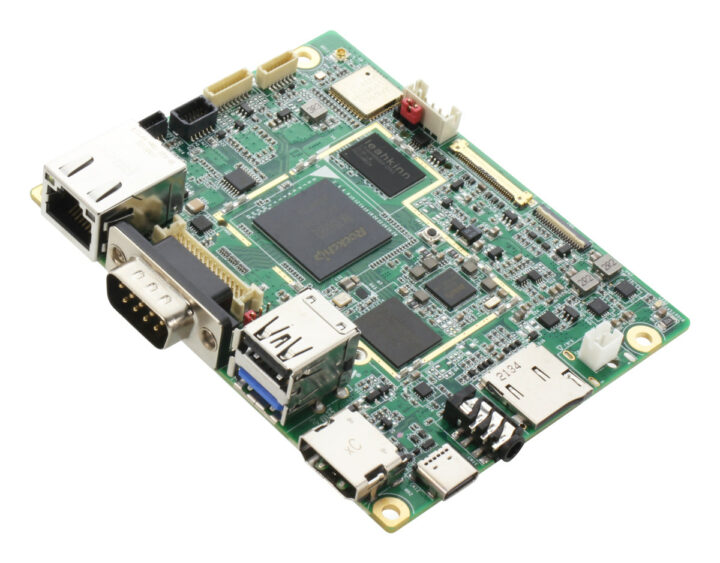


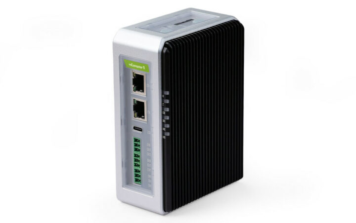


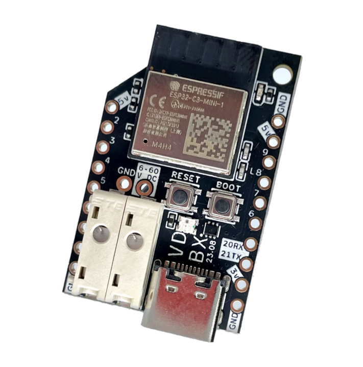


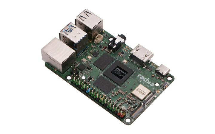


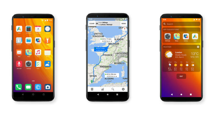


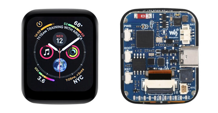


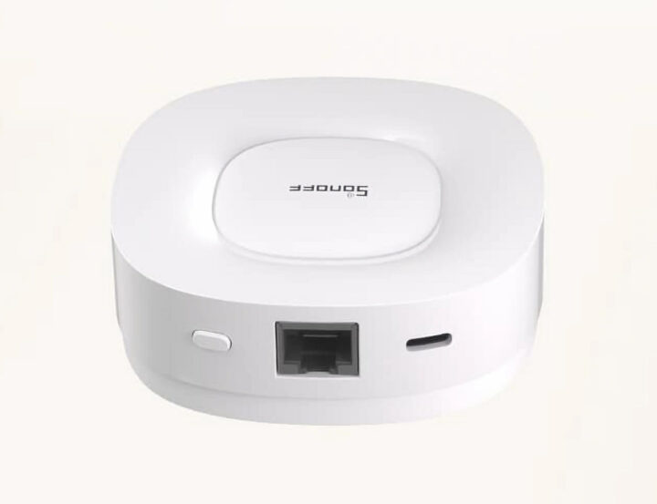
")