We previously noted the ESP32 Arduino Core 3.0.0 Alpha release added support for ESP32-C6 and ESP32-H2 among other changes. The good news is that Arduino ESP32 Core 3.0.0 is now considered stable, and was released a few days ago based on the ESP-IDF 5.1.4 framework. Users of the Arduino IDE can use it straight away, but as we’ll discuss in more detail below it’s unclear whether PlatformIO will be (officially) supported.
There have been many changes since we wrote about the Alpha2 release in Nov
We previously noted the ESP32 Arduino Core 3.0.0 Alpha release added support for ESP32-C6 and ESP32-H2 among other changes. The good news is that Arduino ESP32 Core 3.0.0 is now considered stable, and was released a few days ago based on the ESP-IDF 5.1.4 framework. Users of the Arduino IDE can use it straight away, but as we’ll discuss in more detail below it’s unclear whether PlatformIO will be (officially) supported.
There have been many changes since we wrote about the Alpha2 release in November 2023 with 327 commits from 96 contributors. Some of the most recent changes (compared to RC3) include:
Updated ESPDuino with extra options (CPU freq and Partition)
Add support for WeAct Studio ESP32C3
Attach ETH events at the correct place
Enable the possibility to use SPI ETH with only 4 wires
Fix ETH.end()
Fix ETH.stop() with IDF SPI
Nano ESP32: delete programmer.default entry (on main) due to unintended consequences for CLI users
Update Kconfig.projbuild to fix LittleFS selective compilation
Fixed outdated function signature (ledcWrite)
Remove masking for ADC channel number
Add GPIO pin mappings for M5Stack CamS3 Unit and select OPI PSRAM by default
Provide a default TAG name for USE_ESP_IDF_LOG logging macro
Update merge_package.py to use packaging.version instead of the deprecated distutils.version
You’ll find the release on GitHub for installation in the Arduino IDE just as we did for the Alpha2 release. More ESP32-C6 and ESP32-H2 boards are now supported out of the box, since last time I tried there were only two ESP32-C6 boards and one ESP32-H2 board…
That’s great for users relying on the Arduino IDE, but some prefer working with PlatformIO, and there’s currently an open issue on PlatformIO about support for Arduino ESP32 Core v3.0.0 which may never be officially supported:
The ESP32 Core for Arduino 2.x is the most recent major version currently recommended for use with PlatformIO. The decision to discontinue support was made by the Espressif company, as indicated in their official statement
That’s a long thread, but there seem to be some ongoing commercial discussions between Espressif Systems and PlatformIO developers that are not resolved yet:
[…]
The current supported version is Arduino Core v2.x for ESP32. Our collaboration with Espressif, including discussions about renewal, is ongoing. It’s worth noting that we have @VojtechBartoska, a project manager from Espressif, in this thread. We’re all working together to ensure you receive the best features and support. We’ll keep everyone posted on any updates to ensure a smooth continuation of our services.
[…]
PlatformIO is a commercial open-source project. In the past, it used to be a paid service before 2020, following a business-to-consumer (B2C) model. Unexpectedly, PlatformIO gained widespread popularity among millions of developers globally. Consequently, we shifted our strategy to make powerful tools for professional embedded development freely accessible to everyone.
The active development and maintenance of PlatformIO, along with its infrastructure, are now supported by technology partners dedicated to delivering an excellent developer experience. Espressif was one such partner, and we appreciate their long-standing collaboration.
Currently, Espressif has ceased support for new products in PlatformIO, but rest assured, we are committed to providing support for existing Espressif products integrated before this change, as per our technology licensing policy. Your projects won’t face disruptions, and services will continue as usual.
But it’s unclear whether all features will work, as another user chimed in:
Yep, for the c6 just the entry arduino needs to be added. Anyways C6 does not work “out of the box”. The needed changes to support C2, H2 and C6 are not so many
We’ll have to see how it goes. So it’s possible to use the new Arduino ESP32 Core 3.0.0 with Platform.io with some effort, but if the companies don’t come to an agreement soon, the long-term future of PlatformIO for ESP32 boards is uncertain. Arduino ESP32 Core 2.x is still supported in PlatformIO, so no issues here for existing boards and projects.
The M5Stack CoreS3 SE, also called M5CoreS3 SE, is a cost-down version of the M5Stack CoreS3 IoT controller based on the ESP32-S3 wireless microcontroller with a 2-inch capacitive touch display, a microSD card slot, a USB-C port, a speaker, two microphones, and one Grove connector for expansion.
The M5Core S3 SE loses the DIN Base so the associate features are gone and DIN rail mounting is not possible by default anymore. That also means the M5Stack CoreS3 SE controller is about twice as thin, a
The M5Stack CoreS3 SE, also called M5CoreS3 SE, is a cost-down version of the M5Stack CoreS3 IoT controller based on the ESP32-S3 wireless microcontroller with a 2-inch capacitive touch display, a microSD card slot, a USB-C port, a speaker, two microphones, and one Grove connector for expansion.
The M5Core S3 SE loses the DIN Base so the associate features are gone and DIN rail mounting is not possible by default anymore. That also means the M5Stack CoreS3 SE controller is about twice as thin, and the color is also different (medium grey vs black grey). Major internal changes include the removal of the camera and the three sensors found in the original model.
M5Stack CoreS3 SE specifications with highlights in bold and strikethrough showing differences against the CoreS3 model:
CPU – Dual-core 32-bit Xtensa LX7 microcontroller with AI vector instructions up to 240MHz, RISC-V ULP co-processor
Memory – 512KB SRAM, 8MB PSRAM
Storage – 16MB flash
Connectivity 2.4GHz WiFi 4 (802.11b/g/n), Bluetooth 5.0 BLE + Mesh,
Antenna – Internal “3D” antenna
Storage – MicroSD card slot
Display – 2-inch display with 320×240 resolution via ILI9342C driver, capacitive touch support
Camera – 0.3MP VGA camera @ 30 fps using GC0308 CMOS sensor
Audio
1W speaker connected to AW88298 I2S power amplifier chip
Dual microphones connected to ES7210 audio decoding chip
USB – 1x USB Type-C port
Sensors (none)
LTR-553ALS-WA proximity sensor
BMI270 6-axis gyroscope and accelerometer
BMM150 magnetometer
Expansion
30-pin female header connected to DIN base with
4-pin GPIO Grove connector
4-pin UART Grove connector
4-pin I2C Grove connector
Misc
Power and Reboot buttons
Power switch
BM8563 RTC
Power Supply
5V via USB Type-C port
9V-24V DC input via DC jack (previously in DIN Base)
Built-in 3.7V/500mAh battery (previously in DIN Base)
AXP2101 power management chip
Power consumption
Battery
Standby mode: 4.2V/104.64uA
Active mode: 4.2V/109.67mA
USB power supply – 5V/166.27mA while active
Dimensions – 54x54x16 mm; DIN rail mountable; M3 mounting screws
Weight – 73.3 grams38.4 grams
The M5Stack CoreS3 SE remains programmable with the Arduino IDE or UIFlow visual programming tool, and users can reuse the Arduino library for the CoreS3 available on GitHub as well as some of the Arduino sketches. As one would expect, the code samples making use of the camera and sensors won’t work… Further technical details can be found on the documentation page.
I first found the M5Stack CoreS3 SE on the company’s Aliexpress store where it is sold for $38.90 plus shipping, but you’ll also find it on the M5Stack shop for $38.60. For reference, the original M5Stack CoreS3 IoT controller sells for $59.90, so the discount is significant if you don’t need any of the extra features.
Radxa Fogwise Airbox, also known as Fogwise BM168M, is an edge AI box powered by a SOPHON BM1684X Arm SoC with a built-in 32 TOPS TPU and a VPU capable of handling the decoding of up to 32 HD video streams. The device is equipped with 16GB LPDDR4x RAM and a 64GB eMMC flash and features two gigabit Ethernet RJ45 jacks, a few USB ports, a speaker, and more.
Radxa sent us a sample for evaluation. We’ll start the Radxa Fogwise Airbox review by checking out the specifications and the hardware with an
Radxa Fogwise Airbox, also known as Fogwise BM168M, is an edge AI box powered by a SOPHON BM1684X Arm SoC with a built-in 32 TOPS TPU and a VPU capable of handling the decoding of up to 32 HD video streams. The device is equipped with 16GB LPDDR4x RAM and a 64GB eMMC flash and features two gigabit Ethernet RJ45 jacks, a few USB ports, a speaker, and more.
Radxa sent us a sample for evaluation. We’ll start the Radxa Fogwise Airbox review by checking out the specifications and the hardware with an unboxing and a teardown, before testing various AI workloads with Tensorflow and/or other frameworks in the second part of the review.
Radxa Fogwise Airbox specifications
The specifications below come from the product page as of May 30, 2024:
SoC – SOPHON SG2300x
CPU – Octa-core Arm Cortex-A53 processor up to 2.3 GHz
VPU
Decoding of up to 32x 1080p25 channels with H.265/H.264
Full processing of 32x 1080p25 channels with decoding and AI analysis
Encoding of up to 12x 1080p25 channels with H.265/H.264
JPEG up to 1080p600 (no typo, that’s 600 FPS) up to 32768 x 32768
Video post-processing such as image CSC, Resize, Crop, Padding, Border, Font, Contrast, and Brightness adjustments.
TPU – Tensor Processing Unit with up to 24 TOPS (INT8), 12 TFLOPS (FP16/BF16) and 2 TFLOPS (FP32) with support for TensorFlow, Caffe, PyTorch, Paddle, ONNX, MXNet, Tengine, and DarkNet
System Memory – 16GB LPDDR4X
Storage
64GB onboard eMMC flash
M.2 M Key connector for 2230 NVMe SSD
MicroSD Card slot
Networking
2x Gigabit Ethernet ports
Optional WiFi and Bluetooth via M.2 E Key module
USB
2x USB 3.0 host ports
1x USB Type-C Debug UART port
Power Supply – 20V via USB Type-C port, at least 65W
Dimensions – 104 x 84 x 52mm (metal case with active cooling)
Temperature Range – 0°C to +45°C
Compliance Certification – FCC / CE
The specifications and design are almost exactly the same as the Firefly AIBOX-1684X, but except for the SOPHON BM1684X (32 TOPS) used instead of the SOPHON SG2300x (24 TOPS), and the two M.2 sockets that don’t seem to be available in the Firefly AI box. At the time of the Firefly article (April 2024), I was told that “SG2300X supports open-source generative AI, while the BM1684X does not”, but it appears both chips are interchangeable for more on that below…
Based on the documentation, the Radxa Fogwise Airbox AI micro-server runs the CasaOS lightweight operating system offering a private cloud storage solution for home users. The company also offers a “Radxa Model Zoo” with ResNet-50, YOLOv5-det, YOLOv8-seg for object detection, recognition, and segmentation, and provides instructions to run LVMs or LLMs such as Stable Diffusion and Llama-3.
Fogwise “BM168M” unboxing
The Fogwise Airbox ships in a retail box that reads “Fogwise BM168M Edge Micro-Sever for AI”. Besides the typo, I was surprised by the size of the package as I expected something a bit larger similar to mini PC packages. The other thing is that it’s not called “Fogwise Airbox”, but “Fogwise BM168M” on the package.
In addition, if we look at the bottom side of the package, we can see the basic specifications that read “Power by SOPHON BM1684X” instead of “Powered by SOPHON SG2300X” as I would have expected. The package also lists the supported frameworks: PyTorch, ONNX, Baidu PaddlePaddle, Cafee, Tensforflow, MXNET, and Darknet.
Radxa Fogwise Airbox is shown on the sticker at the bottom, but since the teardown below will reveal more BM1684X strings, I asked Radxa if it was normal I have received a BM1684X device instead of one with SG2300x. I was eventually told I had received the latter as when the Model contains the string “R31” the system is based on SG2300x, while if there’s R22 it is powered by BM1684X. SG2300x and BM1684X are essentially the same chips and the main difference is that SG2300x is a SOPHGO device, while BM1684X refers to Bitmain. The latter is now focused on (crypto) mining hardware.
Raspberry Pi 5 for scale
There’s nothing much inside the case, as the device itself takes 99% of the space, and we only have a “QC passed” sticker and a Warranty card (back side not shown on the photo above) with QR codes on the other side pointing to documentation (link not working, but I found it with a web search, see specifications section) and the community forum. This explains why the package can be so small as users will need to get their own 65W+ USB-C power adapter.
The rear panel includes two USB 3.0 ports, WAN and LAN gigabit Ethernet ports, and a USB-C port for power plus ventilation holes. The left side features a microSD card slot and a USB-C debug port.
The right side has a few holes for the built-in speaker.
Radxa Fogwise Airbox teardown
Let’s have a look inside.
We’ll need to remove the four stick rubber pads and loosen four screws to remove the bottom cover.
This reveals the M.2 Key M and Key E sockets listed in the specifications as well as the cables from two WiFi antennas. There’s a thick thermal pad that covers a chip in the middle.
It happens to be an ASMedia ASM2806 PCIe Gen3 x2 switch with four downstream ports. Let’s remove four standoffs to take the main board out of the enclosure. I also had to disconnect the wire to the speaker (shown on the left in the photo below).
The SOPHGO SG2300x processor is on the CPU module and in contact with the metal case through some thermal paste.
The top of the AIM_1684X_V1 system-on-module also features two Realtek RTL8211FG gigabit Ethernet transceivers and two Micron MT53E1G32D4NQ-053 32Gbit (4GB) LPDDR4 memory chips, meaning there are also two others underneath for a total of 16GB.
A Monolithic Power Systems (MPS) MP7475 PMIC can be found on the bottom right of the module, and a VL805 PCIe to USB 3.0 bridge is present on the mainboard for the two USB 3.0 ports.
The last notable part on the board is the APW8713 8W step-down converter. I did not remove the CPU module which is attached through a single B2B connector to the mainboard.
First try
I reassembled the device to give it a try. None of my USB-C phone chargers will reach 45W and the Raspberry Pi 5 USB-C power supply is limited to 27W, so I used a 100W GaN USB-C power supply from MINIX. I also connected an Ethernet cable to the WAN port. The system automatically started upon applying the power.
I searched for the device with nmap but nothing new showed up…
jaufranc@CNX-LAPTOP-5:~$ nmap -sP 192.168.31.0/24
Starting Nmap 7.80 ( https://nmap.org ) at 2024-05-31 11:03 +07
....
Nmap done: 256 IP addresses (10 hosts up) scanned in 3.88 seconds
So I connected a USB-A to USB-C to the Debug port to access the console and see what was going on…
NOTICE:  GPIO0: 3600
PCIe 33861041007
NOTICE:  BOOT: 7000000/5/0
NOTICE:  Booting Trusted Firmware
NOTICE:  BL1: v2.5(release):bm1686_rom_v6
NOTICE:  BL1: Built : 19:08:47, Jan 24 2022
INFO:    BL1: RAM 0x10002000 - 0x1000d000
INFO:    BL1: Loading BL2
NOTICE:  Try SPIF section B
NOTICE:  Locate FIP in SPI flash (DMMR)
WARNING: Firmware Image Package header check failed.
ERROR:   No suitable image source for 1
WARNING: Failed to obtain reference to image id=1 (-2)
ERROR:   Failed to load BL2 firmware.
NOTICE:  GPIO0: 3600
PCIe 34398516996
NOTICE:  BOOT: 7000000/5/0
NOTICE:  Booting Trusted Firmware
NOTICE:  BL1: v2.5(release):bm1686_rom_v6
The system is stuck in a boot loop… So it looks like I have to install the image myself…
So I downloaded the Fogwise Airbox B4 image and we’re told to flash it to a microSD card with tools like Etcher, but USBImager won’t take the file… and looking into the tarball it’s not your typical img file…
So I think I’ll stop for today and carry on once the documentation has been updated… So I prepared a microSD card with a FAT32 parition and copied the file on it. After that I turned off the device, inserted the microSD card, and restarted it to start the flashing process.
PCIe 110999
NOTICE:  BOOT: 7000000/5/0
NOTICE:  Booting Trusted Firmware
NOTICE:  BL1: v2.5(release):bm1686_rom_v6
NOTICE:  BL1: Built : 19:08:47, Jan 24 2022
INFO:    BL1: RAM 0x10002000 - 0x1000d000
NOTICE:  SD initializing 100000000Hz
NOTICE:  GPIO0: 3600
PCIe 110999
NOTICE:  BOOT: 7000000/5/0
NOTICE:  Booting Trusted Firmware
NOTICE:  BL1: v2.5(release):bm1686_rom_v6
NOTICE:  BL1: Built : 19:08:47, Jan 24 2022
INFO:    BL1: RAM 0x10002000 - 0x1000d000
NOTICE:  SD initializing 100000000Hz
NOTICE:  GPIO0: 3600
PCIe 110999
NOTICE:  BOOT: 7000000/5/0
NOTICE:  Booting Trusted Firmware
NOTICE:  BL1: v2.5(release):bm1686_rom_v6
NOTICE:  BL1: Built : 19:08:47, Jan 24 2022
INFO:    BL1: RAM 0x10002000 - 0x1000d000
NOTICE:  SD initializing 100000000Hz
NOTICE:  GPIO0: 3600
PCIe 110999
NOTICE:  BOOT: 7000000/5/0
NOTICE:  Booting Trusted Firmware
NOTICE:  BL1: v2.5(release):bm1686_rom_v6
NOTICE:  BL1: Built : 19:08:47, Jan 24 2022
INFO:    BL1: RAM 0x10002000 - 0x1000d000
NOTICE:  SD initializing 100000000Hz
NOTICE:  boot from SD
INFO:    BL1: Loading BL2
NOTICE:  Locate FIP in SD FAT
INFO:    Loading image id=1 at address 0x10020000
INFO:    Image id=1 loaded: 0x10020000 - 0x1003e32c
NOTICE:  BL1: Booting BL2
INFO:    Entry point address = 0x10020000
INFO:    SPSR = 0x3c5
NOTICE:  BL2: v2.7(release):83702b19-dirty
NOTICE:  BL2: Built : 06:35:55, May 17 2024
INFO:    BL2: Doing platform setup
NOTICE:  BM1684X board type: 139/54/0x11
NOTICE:  interleave mode 1
NOTICE:  LPDDR4x(rank: 2 + 2, freq: 4000M) init start
NOTICE:  Done.
NOTICE:  Setup A53 Lite Reset Address 00000000101ffff0
NOTICE:  Release A53 Lite
NOTICE:  SD initializing 100000000Hz
INFO:    BL2: Loading image id 3
NOTICE:  Locate FIP in SD FAT
INFO:    Loading image id=3 at address 0x300000000
INFO:    Image id=3 loaded: 0x300000000 - 0x300009124
INFO:    BL2: Loading image id 5
NOTICE:  Locate FIP in SD FAT
INFO:    Loading image id=5 at address 0x308000000
INFO:    Image id=5 loaded: 0x308000000 - 0x3080bba24
NOTICE:  BL1: Booting BL31
INFO:    Entry point address = 0x300000000
INFO:    SPSR = 0x3cd
NOTICE:  BL31: v2.7(release):83702b19-dirty
NOTICE:  BL31: Built : 06:35:55, May 17 2024
INFO:    ARM GICv2 driver initialized
ERROR:   disable secure firewall
INFO:    BL31: Initializing runtime services
INFO:    BL31: Preparing for EL3 exit to normal world
INFO:    Entry point address = 0x308000000
INFO:    SPSR = 0x3c9
found dtb@139: bitmain-bm1684x-sm7m-v1.0
Selecting config 'bitmain-bm1684x-sm7m-v1.0'


U-Boot 2022.10 83702b19-dirty (May 17 2024 - 06:35:49 +0000) Sophon BM1684

DRAM:  1 GiB
Relocation Offset is: 37f49000
Relocating to 33ff49000, new gd at 33f7ffd60, sp at 33f7fe4d0
Core:  38 devices, 20 uclasses, devicetree: fit
WDT:   Started bm16xxwdt@69 with servicing (60s timeout)
MMC:   sdhc@50100000: 0, sdhc@50101000: 1
Loading Environment from FAT...
...
## Executing script at 300040000
fs reading //gpt.gz
446 bytes read in 8 ms (53.7 KiB/s)

Uncompressed size: 17408 = 0x4400


MMC write: dev # 0, block # 0, count 34 ... 34 blocks written: OK

fs reading //boot_emmc-boot.scr
1362 bytes read in 10 ms (132.8 KiB/s)
## Executing script at 300040000
fs reading //boot.1-of-2.gz
24653775 bytes read in 3073 ms (7.7 MiB/s)

Uncompressed size: 102760448 = 0x6200000


MMC write: dev # 0, block # 8192, count 200704 ... 200704 blocks written: OK

fs reading //boot.2-of-2.gz
30566 bytes read in 14 ms (2.1 MiB/s)

Uncompressed size: 31457280 = 0x1E00000
....
This will take a few minutes and end with:
MMC write: dev # 0, block # 29650944, count 200704 ... 200704 blocks written: OK

fs reading //data.2-of-2.gz
10588 bytes read in 11 ms (939.5 KiB/s)

Uncompressed size: 10866688 = 0xA5D000


MMC write: dev # 0, block # 29851648, count 21224 ... 21224 blocks written: OK

eMMC update done
bm savelog 452 bytes written in 10 ms (43.9 KiB/s)
all done
LED 'status' not found (err=-19)
LED 'error' not found (err=-19)
LED 'status' not found (err=-19)
Please remove the installation medium, then reboot
Let’s turn off the device, remove the microSD card (the case is hot so I used a pencil to do so), and boot it again. This time I got to a login prompt:
jaufranc@CNX-LAPTOP-5:~$ bt
No port specified, using ttyUSB0 (last registered). Use -l to list ports.
Trying port ttyUSB0... Connected to ttyUSB0 at 115200 bps.
Escape character is 'Ctrl-]'. Use escape followed by '?' for help.
         Starting Hold until boot process finishes up...
         Starting Terminate Plymouth Boot Screen...
[  OK  ] Finished Hold until boot process finishes up.
[  OK  ] Finished Terminate Plymouth Boot Screen.
[  OK  ] Started Serial Getty on ttyS0.
         Starting Set console scheme...
[  OK  ] Started Hostname Service.
[  OK  ] Finished Set console scheme.
[  OK  ] Started A high performance…er and a reverse proxy server.
[  OK  ] Created slice system-getty.slice.
[  OK  ] Started Getty on tty1.
[  OK  ] Reached target Login Prompts.
         Starting Authorization Manager...
[  OK  ] Started OpenBSD Secure Shell server.
[  OK  ] Started Authorization Manager.

Ubuntu 20.04 LTS Airbox ttyS0

Airbox login: [  OK  ] Finished Resize root files…m to fit available disk space.
And the Airbox also shows with an IP address:
jaufranc@CNX-LAPTOP-5:~/Downloads$ nmap -sP 192.168.31.0/24
Starting Nmap 7.80 ( https://nmap.org ) at 2024-05-31 14:13 +07
...
Nmap scan report for Airbox (192.168.31.71)
Host is up (0.00069s latency).
...
Nmap done: 256 IP addresses (9 hosts up) scanned in 2.33 seconds
But no port 81 opened as we have installed Ubuntu 20.04 and not CasaOS (as advertised in the documentation):
jaufranc@CNX-LAPTOP-5:~/Downloads$ nmap -F 192.168.31.71
Starting Nmap 7.80 ( https://nmap.org ) at 2024-05-31 14:16 +07
Nmap scan report for Airbox (192.168.31.71)
Host is up (0.0011s latency).
Not shown: 97 closed ports
PORT     STATE SERVICE
22/tcp   open  ssh
80/tcp   open  http
8888/tcp open  sun-answerbook

Nmap done: 1 IP address (1 host up) scanned in 0.03 seconds
We can use the command line through the serial console or SSH using linaro username and linaro password, and run a few commands to get system information:
linaro@192.168.31.71's password:
Welcome to Ubuntu 20.04 LTS (GNU/Linux 5.4.217-bm1684-g18c6a7c915a2-dirty aarch64)

 * Documentation:  https://help.ubuntu.com
 * Management:     https://landscape.canonical.com
 * Support:        https://ubuntu.com/advantage

 * Strictly confined Kubernetes makes edge and IoT secure. Learn how MicroK8s
   just raised the bar for easy, resilient and secure K8s cluster deployment.

   https://ubuntu.com/engage/secure-kubernetes-at-the-edge
overlay / overlay rw,relatime,lowerdir=/media/root-ro,upperdir=/media/root-rw/overlay,workdir=/media/root-rw/overlay-workdir 0 0
/dev/mmcblk0p5 /media/root-rw ext4 rw,relatime 0 0
/dev/mmcblk0p4 /media/root-ro ext4 ro,relatime 0 0

Last login: Fri May 31 15:14:48 2024
linaro@Airbox:~$ cat /etc/issue
Ubuntu 20.04 LTS \n \l

linaro@Airbox:~$ uname -a
Linux Airbox 5.4.217-bm1684-g18c6a7c915a2-dirty #4 SMP Thu May 16 09:59:04 UTC 2024 aarch64 aarch64 aarch64 GNU/Linux
linaro@Airbox:~$ sudo inxi -Fc0
System:    Host: Airbox Kernel: 5.4.217-bm1684-g18c6a7c915a2-dirty aarch64 bits: 64
           Console: tty 0 Distro: Ubuntu 20.04 LTS (Focal Fossa)
Machine:   Type: ARM Device System: Radxa AICore BM1684x IO Board details: N/A
CPU:       Topology: 8-Core (2-Die) model: bm1684x variant: cortex-a53 bits: 64
           type: MCP MCM
           Speed: 2300 MHz min/max: 1150/2300 MHz Core speeds (MHz): 1: 2300 2: 2300
           3: 2300 4: 2300 5: 2300 6: 2300 7: 2300 8: 2300
Graphics:  Message: No Device data found.
           Display: server: No display server data found. Headless machine? tty: 95x33
           Message: Advanced graphics data unavailable in console for root.
Audio:     Device-1: Realtek type: USB driver: hid-generic,snd-usb-audio,usbhid
           Sound Server: ALSA v: k5.4.217-bm1684-g18c6a7c915a2-dirty
Network:   Device-1: ethernet driver: bm_dwmac
           Device-2: ethernet driver: bm_dwmac
           IF-ID-1: docker0 state: down mac: 02:42:cc:48:f3:4a
           IF-ID-2: dummy0 state: down mac: 5a:73:15:58:ea:4e
           IF-ID-3: eth0 state: up speed: 1000 Mbps duplex: full mac: 00:e0:4c:05:7b:70
           IF-ID-4: eth1 state: down mac: 00:e0:4c:05:7b:71
           IF-ID-5: sit0 state: down mac: 00:00:00:00
Drives:    Local Storage: total: 58.24 GiB used: 3.02 GiB (5.2%)
           ID-1: /dev/mmcblk0 model: CUTB42 size: 58.24 GiB
Partition: ID-1: / size: 5.82 GiB used: 170.2 MiB (2.9%) fs: overlay source: ERR-102
           ID-2: /boot size: 127.7 MiB used: 62.2 MiB (48.7%) fs: vfat dev: /dev/mmcblk0p1
           ID-3: /opt size: 1.90 GiB used: 166.8 MiB (8.6%) fs: ext4 dev: /dev/mmcblk0p6
Sensors:   Message: No sensors data was found. Is sensors configured?
Info:      Processes: 188 Uptime: 5m Memory: 3.83 GiB used: 377.3 MiB (9.6%) Init: systemd
           runlevel: 5 Shell: bash inxi: 3.0.38
There’s also a web dashboard on port 80.
This time I’ll stop for now, and I have to figure out what to do next and learn how to use the system.
[One more small update… I’ve just realized CasaOS is not an OS, but a program installed on top of Ubuntu, Debian, etc…..
wget -qO- https://get.casaos.io | sudo bash
]
In the second part of the review, I plan to install the OS and run large language models (LLM) and large vision models (LVM) on the system. I’d like to thank Radxa for sending the Fogwise Airbox for review. It’s now available on Allnet and Arace for $321 plus shipping, and it looks like people who order now on Arace may get a gift set that includes a 20V/3A power adapter, a USB microphone, and a WiFi 6 module.
Waveshare 2-CH CAN MiniPCIe is a compact, CAN bus card featuring dual independent CAN channels with a wide baud rate range (10Kbps to 1Mbps). Unlike the esd electronics CAN-PCIeMiniHS/402, this Waveshare card is isolated, supports CAN2.0A/B protocols, and offers easy integration with laptops, industrial computers, and SBCs like Raspberry Pi via Mini PCIe or USB through an adapter. Additionally, the card supports Windows and Linux operating systems, making it ideal for applications like industria
Waveshare 2-CH CAN MiniPCIe is a compact, CAN bus card featuring dual independent CAN channels with a wide baud rate range (10Kbps to 1Mbps). Unlike the esd electronics CAN-PCIeMiniHS/402, this Waveshare card is isolated, supports CAN2.0A/B protocols, and offers easy integration with laptops, industrial computers, and SBCs like Raspberry Pi via Mini PCIe or USB through an adapter. Additionally, the card supports Windows and Linux operating systems, making it ideal for applications like industrial automation and automotive diagnostics and development.
Waveshare 2-CH CAN MiniPCIe CAN bus card specifications
CAN Bus
CAN channel – Dual-channel: CAN1 and CAN2 (independent and isolated)
Connector – CAN bus screw terminal (standard 1.25mm pitch)
Terminal resistor – Each CAN channel has a 120Ω terminal resistor
Baud Rate – 10Kbps~1Mbps (Configurable via software)
Protocol Support – CAN2.0A and CAN2.0B protocols, complies with ISO/DIS11898-1/2 standards
Hardware Support – High-speed CAN
Transfer speed – The receiving and sending of each CAN channel can reach: 8500 frames/s
Transmit buffer – 2000 frames receiving buffer and 1000 frames sending buffer per channel (automatically retransmit when transmission fails)
Mini PCIe Interface
Operating voltage – 3.3V
Communication method – USB 2.0 pins of the Mini PCIe interface
Indicators
PWR – Power indicator
SYS – System status indicator, normally off; keeps on when there is a bus error
CAN1 – CAN1 channel indicator (blinking when sending and receiving data)
CAN2 – CAN2 channel indicator (blinking when sending and receiving data)
Dimensions – 51×30 mm (mini PCIe module)
Operating Temperature – -40 to +85°C
The CAN protocol is fully compliant with the CAN2.0B specification, including backward compatibility with CAN2.0A, and complies with ISO11898-1/2 standards. Furthermore, it includes support for Windows XP/7/8/10/11 (32/64 bits) as well as various Linux distributions such as Raspberry Pi OS, Ubuntu (Jetson Nano), and VMware virtual PC environments.
Pinout diagram
for simplicity, the company also provides a pinout diagram of the mini PCIe interface for those who want to check things out in more detail.
The 2-CH CAN MiniPCIe adapter can directly be connected to the MiniPCIe slot of a CM4 baseboard or used with a laptop via a USB to MiniPCIe adapter board. Additionally, it connects to a Raspberry Pi using the same USB to MiniPCIe adapter, providing flexible solutions for a wide range of applications and ensuring robust CAN bus communication across different platforms.
The company provides examples for C++Builder, C#, VC, VB, VB.NET, Delphi, LabVIEW, LabWindows/CVI, Qt, and Matlab. Additionally, there are Python and Python-can samples, as well as Qt examples for Linux. This ensures that developers can easily work with CAN bus communication in their preferred development environments. more information about that can be found on the wiki page.
The LILYGO T-Camera-Plus-S3 is an ESP32-S3 development board designed for building smart home devices, monitoring systems, and other connected projects. The board features a 1.3-inch TFT LCD and the option to choose from OV2640 or OV5640 camera modules.
The T-Camera-Plus-S3 can be considered an upgrade from the T-Camera S3, which was introduced in 2022. The upgraded features include a 1.3″ SPI TFT LCD (240×240), a microphone with MAX98357A codec and external speaker support, support for a micro
The LILYGO T-Camera-Plus-S3 is an ESP32-S3 development board designed for building smart home devices, monitoring systems, and other connected projects. The board features a 1.3-inch TFT LCD and the option to choose from OV2640 or OV5640 camera modules.
The T-Camera-Plus-S3 can be considered an upgrade from the T-Camera S3, which was introduced in 2022. The upgraded features include a 1.3″ SPI TFT LCD (240×240), a microphone with MAX98357A codec and external speaker support, support for a micro SD card, a battery connector, and many other features.
SoC – ESP32-S3R8 dual-core Tensilica LX7 microcontroller @ 240 MHz (Note: this SKU is not listed in the official ESP32-S3 datasheet) with
2.4 GHz 802.11n WiFI 4 and Bluetooth 5.0 LE connectivity
Memory – 8MB PSRAM
Storage – 16MB SPI flash
Storage – MicroSD card socket
Camera – 2MP OV2640 camera (Optional 5MP OV5640) with IR-Cut for enhanced low-light performance
Display
1.3″ 240 x 240 fp-133h0M1d TFT display with ST7789V driver chip controlled via SPI
Touch – CST816S chip controlled via I2C
Speaker – 3.2W 14×7.1×3.9cm FS2011NB0807x speakers driver via I2S with MAX98357A driver chip
Microphone – Standard microphone driven via MSM261S4030H0R driver chipo
USB – 1x USB Type-C port for power and programming
Expansion – 2x QWIIC connectors
Misc – Boot button (under the camera), Power and reset buttons
Power Supply
5V via USB Type-C port
2-pin 1.25mm JST-GH connector for battery
Dimensions
Board only: 69 x 28 x 18.5 mm (including PIR dome)
Shell: 75 x 35 x 12 mm
The board features two Qwiic connectors and multiple exposed GPIO pins on the board to support protocols like I2C, SPI, and serial connections.
In terms of software and programming the board supports programming with the Arduino IDE, VS code, and platform IO. Usually, the company provides links to resources but this time it was a little hard to find, upon looking I found a GitHub repository with examples of the camera, SD music, touchscreen, and more.
The LILYGO T-Camera-Plus-S3 is available for purchase through LILYGO’s official AliExpress store with a price tag of $37.98 including shipping. The company also posted a live demonstration video on its X account.
The Dusun DSGW-130 smart home controller is a Rockchip PX30-powered, touch-enabled control panel designed to fit into an 86-type junction box. It runs on Android 11 and can connect to your home network using Wi-Fi and Zigbee, similar to the SONOFF NSPanel Pro. The only glaring difference I can see from the specifications is that the DSGW-130 has a few extra features like more storage, a wired network connection, RS485, and support for newer 5GHz Wi-Fi, which the SONOFF doesn’t have.
We’ve also w
The Dusun DSGW-130 smart home controller is a Rockchip PX30-powered, touch-enabled control panel designed to fit into an 86-type junction box. It runs on Android 11 and can connect to your home network using Wi-Fi and Zigbee, similar to the SONOFF NSPanel Pro. The only glaring difference I can see from the specifications is that the DSGW-130 has a few extra features like more storage, a wired network connection, RS485, and support for newer 5GHz Wi-Fi, which the SONOFF doesn’t have.
Dusun DSGW-130 smart home controller specifications
SoC – Rockchip PX30 quad-core Cortex-A35 processor with Arm Mali-G31 GPU
System Memory – 1GB DDR3
Storage – 8GB eMMC 5.1 flash
Display – 4-inch capacitive touchscreen color TFT display with 480×480 resolution
Audio – Dual microphones and 1 speaker
Connectivity
Zigbee 3.0
Built-in Wi-Fi Module (2.4GHz / 5GHz)
1 WAN/LAN variable port with 10/100 Mbps connectivity
1x RS485
Power Input – 100-240V AC 50/60Hz
Installation Method – Wall mounting
IP Rate – IP22
Dimension (W x D x H):
With Base: 86 x 86 x 40 MM
Without Base: 86 x 86 x 10.5MM
Weight – 225g
Operating Temperature: -10℃~60℃
Storage Temperature: -20℃~65℃
Operating Humidity – 10%~90% non-condensing
Storage Humidity – 5%~90% non-condensing
Certification – CE, FCC, RoHS
The Dusun DSGW-130 smart home also has voice control, enabled by dual built-in microphones and speakers, allowing users to develop custom voice command features. Additionally, Dusuniot’s specifications page confirms that the module has a transmission range of up to 50 meters and a maximum speed of 300Mbps.
Regarding software and development tools the company mentions that DSGW-130 supports secondary development meaning users can create their applications with the help of development resources and documentation, which are not available at the time of writing.
The Dusun DSGW-130 smart home controller is priced at $162.00 and can be directly purchased through the Dusun online store.
We previously tested Edge Impulse machine learning platform showing how to train and deploy a model with IMU data from the XIAO BLE sense board relatively easily. Since then the company announced support for NVIDIA TAO toolkit in Edge Impulse, and now they’ve added the latest GPT-4o LLM to the ML platform to help users quickly train TinyML models that can run on boards with microcontrollers.
What’s interesting is how AI tools from various companies, namely NVIDIA (TAO toolkit) and OpenAI (GPT-4o
We previously tested Edge Impulse machine learning platform showing how to train and deploy a model with IMU data from the XIAO BLE sense board relatively easily. Since then the company announced support for NVIDIA TAO toolkit in Edge Impulse, and now they’ve added the latest GPT-4o LLM to the ML platform to help users quickly train TinyML models that can run on boards with microcontrollers.
What’s interesting is how AI tools from various companies, namely NVIDIA (TAO toolkit) and OpenAI (GPT-4o LLM), are leveraged in Edge Impulse to quickly create some low-end ML model by simply filming a video. Jan Jongboom, CTO and co-founder at Edge Impulse, demonstrated the solution by shooting a video of his kids’ toys and loading it in Edge Impulse to create an “is there a toy?” model that runs on the Arduino Nicla Vision at about 10 FPS.
Another way to look at it (hence the title of the video embedded below) is that they’ve shrunk GPT-4o LLM with over 175 billion parameters to a much smaller specialized model with only 800K parameters suitable to run on MCU hardware.
There are five basic steps to achieve this:
Data Collection: shooting a video
Data Processing: Uploading the video to Edge Impulse to split it by frames with data unlabeled.
Labeling with GPT-4o: Using the new transformation block “Label image data using GPT-4o” in Edge Impulse, users can ask GPT-4o to label the images automatically, discarding any blurry or uncertain images to provide a clean dataset. The question was “is there any toy?”, and the answer could only be “yes” or “no”.
Model Training: Once the images are labeled (there are about 500 labeled items in the demo), NVIDIA TAO is used to train a small (MobileNet) model with these images. The model in the demo ended up having about 800,000 parameters.
Deployment: The model can now be deployed on the hardware from the web interface. In this case, an Arduino Nicla Vision could accurately detect toys on-device, in real-time (10FPS) without requiring cloud services. That model was also tested in a web browser at 50 FPS and on an iPhone.
You can watch the video below with Jan going through the main steps in about 14 minutes.
While some features of Edge Impulse are free to use, the GPT-4o labeling block and TAO transfer learning models are only available to enterprise customers in Edge Impulse. If you have a company email address, there’s a 2-week free trial available. More details may be found in the announcement.
Example of SoC with Arm’s 2024 IP (TCS 2024)
Arm has just announced new Armv9 CPUs and Immortalis GPUs for mobile SoCs, as well as the Kleidi AI software optimized for Arm CPUs from Armv7 to Armv9 architectures.
New Armv9.2 CPU cores include the Cortex-X925 “Blackhawk” core with significant CPU and AI performance improvements, the Cortex-A725 with improved performance efficiency, and a refreshed version of the Cortex-A520 providing 15 percent efficiency improvements. Three new GPUs have also bee
Arm has just announced new Armv9 CPUs and Immortalis GPUs for mobile SoCs, as well as the Kleidi AI software optimized for Arm CPUs from Armv7 to Armv9 architectures.
New Armv9.2 CPU cores include the Cortex-X925 “Blackhawk” core with significant CPU and AI performance improvements, the Cortex-A725 with improved performance efficiency, and a refreshed version of the Cortex-A520 providing 15 percent efficiency improvements. Three new GPUs have also been introduced namely the up-to-14-core Immortalis-G925 flagship GPU which delivers up to 37% 3D graphics performance improvements over last year’s 12-core Immortalis-G720, the Mali-G725 with 6 to 9 cores for premium mobile handsets, and the Mali-G625 GPU with one to five cores for smartwatches and entry-level mobile devices.
Arm Cortex-X925
The Arm Cortex-X925 delivers 36 percent single-threaded peak performance improvements in Geekbench 6.2 against a Cortex-X4-based Premium Android smartphone, and about 41 percent better AI performance using the time-to-first token of tiny-LLama (Q4). The Cortex-X925 core was implemented on an FPGA platform with the following configuration: Cortex-X925 @ 3.8 GHz with 2MB L2 cache, 16MB L3, 32MB SLC, DSU @ 2 GHz, and LPDDR5x-8533 memory.
The AI performance was measured to be improved by 46 percent using the time-to-first token for Phi3, and Arm also says X925 SoCs can deliver 33 percent faster application launch times on average across five of the top 10 applications (in Android), and 60 percent faster web browsing measured using the Speedometer 2.1 browser benchmark. The slides shared by Arm mention support for Android, Linux, and Windows operating systems, so it will not only be used in smartphones but also mobile and AI PCs.
The Arm Cortex-X925 core is optimized for 3nm manufacturing processes. You’ll find more technical details about the new core on the developer’s website.
Arm Cortex-A725 and improvements for the Cortex-A520 core.
The Cortex-A725 further improves the performance and efficiency compared to the Cortex-A720 and Cortex-A78 cores. The new core delivers a 35 percent performance efficiency boost over the Cortex-A720, a 25 percent better power efficiency, and 20% L3 traffic improvements. Performance efficiency is defined as the ratio between the improvement in Performance and the improvement in Power for the said performance. The Cortex-A725 peak performance was apparently measured on a 3nm test chip with 64KB K1 and 8MB L3 caches, and compared to a 4nm Cortex-A720 chip. Besides the different process nodes, Arm claims most of the improvements to performance efficiency are due to the microarchitecture of the Cortex-A725.
The Cortex-A520 has been refreshed with updated implementation and a 3nm process delivering up to 15 percent efficiency improvements compared to Cortex-A520 in TCS23.
Immortalis-G925, Mali-G725, and Mali-G625 GPUs
Like the Arm Cortex-X925 CPU, the Immortalis-G925 offers significant performance improvements over the previous generation Immortalis-G720 with 37% better performance in graphics apps, 34% faster AI inference (testing in fp16 mode), and 52% faster ray tracing. Arm further states that the Immortalis-G925 GPU delivers 46 percent performance improvements in mobile, on average, compared to the Immortalis-G720. Some examples include Genshin Impact with a 49 percent boost and Roblox which is 46 percent faster, and the company also tested Call of Duty Mobile, Diablo Immortal, the Day After Tomorrow, Fortnite, and PUBG Mobile with improvements ranging from 29 to 72 percent. We’re also told efficiency has improved by 30 percent on average in leading games.
Immoratlis-G925 AI performance improvements with image classification, image segmentation, object detection, natural language processing, and more…
Arm did not expand on the Mali-G725 and Mali-G625 GPUs. Those look to be smaller variants of the Immortalis-G925 with fewer cores and now ray tracing capabilities optimized for mid-range and entry-level devices.
Kleidi AI software
Arm Kleidi is a suite of software libraries and developer communities designed to accelerate AI development. The Arm Kleidi libraries support popular AI frameworks and are optimized for Arm CPUs from the Armv7 architecture using the Advanced Single Instruction Multiple Data (SIMD) Extension for machine learning (ML) workloads up to the new Armv9 architecture with more advanced features enabling generative AI workloads on the Arm CPU.
Kleidi is comprised of two main projects for now: KleidiAI for neural networks and inference engines and KleidiCV for OpenCV computer vision library.
KleidiAI is a collection of highly optimized AI kernels that work through MediaPipe (via XNNPACK), LLAMA.cpp, PyTorch (via ExecuTorch), and TensorFlow Lite (via XNNPACK). Arm says KleidiAI can accelerate the time-to-first token for Meta’s Llama 3 and Microsoft’s Phi-3 LLMs using llama.cpp by 190 percent on the new Arm Cortex-X925 CPU compared with the reference implementation based on llama.cpp. KlaidiAI is also being integrated into Unity Sentis on-device AI inference engine for game developers
KleidiCV is developed in partnership with OpenCV to optimize over 2500 computer vision algorithms in the popular open-source library. NEON/SVE2-optimized implementations deliver a 75 percent performance uplift on average. Android builds are also being submitted to the Maven Central repository of open-source software components and libraries for Java development
You’ll find a few more details about Kleidi in the announcement.
All those new IP blocks and software make the Arm Compute Subsystems for Client (Arm CSS for Client) that will be integrated into SoCs for AI PCs, smartphones, consumer devices, and more. We’ll likely have to wait until 2025 at least before the first devices with Arm Cortex-X925 or Cortex-A725 come to market.
Ochin V2 is an update to the tiny Ochin Raspberry Pi CM4 carrier board for robotics applications and drones that adds a micro HDMI port, support for Fast Ethernet through pads or a GHS connector (no RJ45 connector), two user LEDs, and a few other changes.
The form factor remains the same at just 55 x 40 x 4.7mm, or about the size of a Raspberry Pi Compute Module 4, which in combination with a range of USB, UART, I2C, and SPI interfaces, makes it an ideal candidate for space-constrained applicati
Ochin V2 is an update to the tiny Ochin Raspberry Pi CM4 carrier board for robotics applications and drones that adds a micro HDMI port, support for Fast Ethernet through pads or a GHS connector (no RJ45 connector), two user LEDs, and a few other changes.
The form factor remains the same at just 55 x 40 x 4.7mm, or about the size of a Raspberry Pi Compute Module 4, which in combination with a range of USB, UART, I2C, and SPI interfaces, makes it an ideal candidate for space-constrained applications such as robotics system or UAVs.
Ochin v2 carrier board with small USB-C board
Ochin V2 specifications (differences against Ochin v1 shown in bold or strikethrough):
Supported modules – Raspberry Pi CM4 with Broadcom BCM2711 quad-core Cortex-A72 processor, up to 8GB RAM, up to 32GB eMMC flash (the CM4 Lite is not supported since there’s no microSD card on the board), 4Kp60 H.265 decode, 1080p30 H.264 encode, and optional WiFi 5 and Bluetooth 5.0
Networking – 6-pin SPI GHS connector or soldering pads for 10/100M Ethernet (See pinout diagram below)
USB – 1x USB 2.0 Type-C port available through a small external board with RGB LED, button, and a USB Type-C port
I/Os
4x USB 2.0 GHS connectors
6-pin SPI GHS connector (Shared with 10/100M Ethernet)
4-pin I2C GHS connector
GHS Connector with UART 0/1 (only one interface selectable), composite video out, 5V, 3.3V, and GND
UART 3/5 GHS connector (both interfaces) replaced by USB ext GHS connector with USB 2.0, I2C, nRPIBoot, VOTG, 3.3V, and GND
USART4/5 GHS connector
14-pin expansion header with 2x UART, composite video out, Vin-/Vin+, GNS
Misc
Boot mode button
IN219 current sensor
Current limiter bypass
2x general-purpose LEDs
Power Supply
7.5V to 28V via DC power supply
2S to 6S LiPo battery
DC-DC regulator that provides up to 7Amp
Dimensions – 55 x 40 x 4.7mm
Ochin V2 carrier board pinout diagramExample of a transformerless Ethernet cable from Ochin V2 documentation
The Ochin V2, also called Ochin CM4v2, is designed to work with OpenHD open-source software that makes it possible to transmit an HD video stream with low latency from a mobile station such as a rover, a drone, a plane, etc… to a ground station. A web interface is also provided to simplify the configuration and management of the CM4 module. As for the Ochin V1, a Raspberry Pi CM4’s heatsink is recommended.
Like its predecessor, the Ochin V2 board is partially open-source with the KiCad PDF schematics and 3D models for accessories such as camera mounts and an extractor for the CM4 module available on Github along with documentation and some Python scripts.
Botton sides of the Ochin CM4v2 and “USB-C” board
The Ochin V2 Raspberry Pi CM4 robotics carrier board is sold on Seeed Studio for $59.99, or the same price as the Ochin V1 which has now reached end-of-life status.
Waveshare ESP32-S3-Touch-LCD-7 is an ESP32-S3 powered WiFi 4 and Bluetooth 5 LE 7-inch touchscreen display with plenty of expansion interfaces such as RS485, CAN Bus, I2C, UART, and Analog input that can be used to develop various HMI applications
We’ve written about many ESP32 boards with displays, but most are small displays under 3-inch, and larger displays are more of a rarity except for ESP32 e-Paper displays such as the Inkplate 10 or LILYGO 7.5-inch e-Paper display. Most are based on ESP3
Waveshare ESP32-S3-Touch-LCD-7 is an ESP32-S3 powered WiFi 4 and Bluetooth 5 LE 7-inch touchscreen display with plenty of expansion interfaces such as RS485, CAN Bus, I2C, UART, and Analog input that can be used to develop various HMI applications
We’ve written about many ESP32 boards with displays, but most are small displays under 3-inch, and larger displays are more of a rarity except for ESP32 e-Paper displays such as the Inkplate 10 or LILYGO 7.5-inch e-Paper display. Most are based on ESP32-S3 since it comes with an RGB LCD interface, and the only other 7-inch ESP32-S3 touchscreen display we’ve looked into is the Elecrow 7.0-inch display with specifications similar to the Waveshare ESP32-S3-Touch-LCD-7, but fewer I/O headers.
Waveshare ESP32-S3-Touch-LCD-7:
Wireless module – ESP32-S3-WROOM-1
MCU – ESP32-S3N8R8 dual-core Tensilica LX7 up to 240 MHz with 512KB SRAM, 8MB PSRAM, 8MB flash
Wireless – 2.4 GHz WiFi 4 and Bluetooth LE 5
PCB antenna
Storage – MicroSD card slot
Display – 7-inch capacitive touch screen with 800×480 resolution, 65K colors, 154.88×86.72 mm viewing area
USB
1x USB Type-C port for power and programming
1x USB Type-C UART port (UART1) via CH343P USB to TTL chip
Expansion
UART connector (UART2)
Analog sensor connector
CAN bus connector
I2C connector with 3.3V/5V selected by resistor
RS485 connector with 120-ohm termination resistors connected via jumpers
Misc
BOOT and Reset buttons
UART selection switch
Power, Charging, and Done (full charge) LEDs
Power Supply
5V via USB-C port
2-pin connector for 3.7V battery
Dimensions – 193 x 110.8 mm
Waveshare says the display can be programmed with MicroPython, the Arduino IDE, or the ESP-IDF framework but the wiki only really provides instructions and code samples for the latter two. One of those is the LVGL benchmark reaching 26 FPS on a single core using the ESP-IDF v5.3, and the company claims it corresponds to an interface frame rate of 41 FPS with PCLK set to 21 MHz. I’m not quite sure how the math works here, but this document is supposed to provide some pointers concerning LVGL performance optimization.
Large Language Models (LLMs) can run locally on mini PCs or single board computers like the Raspberry Pi 5 but with limited performance due to high memory usage and bandwidth requirements. That’s why Picovoice has developed the picoLLM Inference Engine cross-platform SDK optimized for running compressed large language models on systems running Linux (x86_64), macOS (arm64, x86_64), and Windows (x86_64), Raspberry Pi OS on Pi 5 and 4, Android and iOS mobile operating systems, as well as web brows
Large Language Models (LLMs) can run locally on mini PCs or single board computers like the Raspberry Pi 5 but with limited performance due to high memory usage and bandwidth requirements. That’s why Picovoice has developed the picoLLM Inference Engine cross-platform SDK optimized for running compressed large language models on systems running Linux (x86_64), macOS (arm64, x86_64), and Windows (x86_64), Raspberry Pi OS on Pi 5 and 4, Android and iOS mobile operating systems, as well as web browsers such as Chrome, Safari, Edge, and Firefox.
Alireza Kenarsari, Picovoice CEO, told CNX Software that “picoLLM is a joint effort of Picovoice deep learning researchers who developed the X-bit quantization algorithm and engineers who built the cross-platform LLM inference engine to bring any LLM to any device and control back to enterprises”.
The company says picoLLM delivers better accuracy than GPTQ when using Llama-3.8B MMLU (Massive Multitask Language Understanding) as a metric as shown in the diagram below with the most gain being when using 2-bit settings. The 4-bit INT result has the same MMLU score as the 16-bit float result.
MMLU comparison between picoLLM and GPTQ for Llama-3-8b
You’ll find some demos, the SDK, and demos for various programming languages and platforms on GitHub. The solution is completely free for open-weight models but requires an access key that is verified by connecting to a server. After access key verification, all LLM processing is done offline and on-device.
We’ve written about Picovoice since 2020, as they offer easy-to-use voice activity detection (VAD) (Cobra), custom wake word (Porcupine), speech-to-text (Leopard and Cheetah), and voice recognition (Rhino) solutions that are fairly easy to use and work on low-end hardware such as Raspberry Pi and Arduino. The company has now combined several of those software solutions with the picoLLM implementation to create an LLM-powered voice assistant written in Python and shown to run on the Raspberry Pi 5 in the video embedded below.
WCH CH32V002 is an industrial-grade general-purpose 32-bit RISC-V microcontroller that is pin-to-pin compatible with the popular CH32V003 MCU with 4KB SRAM instead of 2KB, a wider input voltage range from 2V to 5V, and other improvements.
Earlier this month we wrote about the WCH CH32V006 RISC-V microcontroller that offers an upgrade to the CH32V003 with more I/Os, memory, and storage, requiring a new PCB layout. But now, the Chinese company has unveiled a pin-compatible alternative with the CH3
WCH CH32V002 is an industrial-grade general-purpose 32-bit RISC-V microcontroller that is pin-to-pin compatible with the popular CH32V003 MCU with 4KB SRAM instead of 2KB, a wider input voltage range from 2V to 5V, and other improvements.
Earlier this month we wrote about the WCH CH32V006 RISC-V microcontroller that offers an upgrade to the CH32V003 with more I/Os, memory, and storage, requiring a new PCB layout. But now, the Chinese company has unveiled a pin-compatible alternative with the CH32V002 that adds more SRAM, uses the new V2C core with RV32EmC instruction set (also used in the CH32V006), offers a larger bootloader and configuration memories, upgrades the ADC to 12-bit, and adds support for 8-channel touch-key channel detection.
WCH CH32V002 specifications (highlights in bold show differences against the CH32V003):
The CH32V002 is offered in five packages including four which are pin-to-pin compatible with the CH32V003, and a new QFN12 package with eleven GPIOs. WCH has yet to publish a product page, but the datasheet is already available in English. Software tools such as MounRiver or GCC will be compatible, but the “M” standard extension for integer multiplication and division “m” (Zmmul) multiplication subset of the M extension may need an updated toolchain.
I was unable to find a CH32V002 development board, but it’s just a question of time before those become available along sub one-dollar CH32V003 boards. There’s also a new CH32V004 whose specifications are about the same as the CH32V002 but with 6KB and 32KB of flash instead. Only 20-pin packages are available for that model.
Jetway JNUC-ADN1 is an Intel N97-powered SBC in the Next Unit of Computing (NUC) form factor. The SBC can be equipped with up to 16GB DDR5 RAM via a single SO-DIMM socket, 64GB of eMMC storage, and dual M.2 sockets for additional storage and networking. The SBC comes with two 2.5GbE Ethernet ports and has an operating temperature range of -20°C ~ 60°C, making it suitable for Edge Computing, IoT, and industrial applications.
Jetway offers four variants of their NUC-ADN1 SBC whereas the N97000 ver
Jetway JNUC-ADN1 is an Intel N97-powered SBC in the Next Unit of Computing (NUC) form factor. The SBC can be equipped with up to 16GB DDR5 RAM via a single SO-DIMM socket, 64GB of eMMC storage, and dual M.2 sockets for additional storage and networking. The SBC comes with two 2.5GbE Ethernet ports and has an operating temperature range of -20°C ~ 60°C, making it suitable for Edge Computing, IoT, and industrial applications.
Jetway offers four variants of their NUC-ADN1 SBC whereas the N97000 version does not include eMMC or TPM 2.0 security, the N97002 version features TPM 2.0 but doesn’t have eMMC, the N97004 version omits TPM 2.0 but offers 64GB of eMMC storage, and finally the N97008 version has both TPM 2.0 and 64GB of storage.
Previously we have written about similar SBCs from Jetway like the JF35-ADN1 and the Jetway MI05-0XK, we also covered several N97-based industrial SBCs like the GIGAIPC PICO-N97 and the AAEON PICO-ADN4 feel free to check all those out if you are looking for similar SBCs.
OS support – Windows 10 (64-bit), Windows 11 (64-bit), Linux
Dimensions – 101 x 101mm (4″ x 4″) Intel NUC form factor
Jetway JNUC-ADN1 SBC Block Diagram
In terms of software, this SBC supports Linux, Windows 10, and Windows 11 images which can be found in the download section of their products page. Additionally, the company provides a datasheet of the SBC found on the same page.
At the time of writing the company has not provided any pricing information for the Jetway JNUC-ADN1 SBC, but for more details and order-related information, you can check out the inquiry section of the products page.
The HealthyPi Move is the latest biometric monitor in the HealthyPi series from ProtoCentral. It is the first to come in a wearable form factor and can measure up to eight vital signs.
It is powered by a Nordic Semiconductor nRF5340 dual-core SoC, with a Cortex-M33 application processor and a Cortex-M33 network processor. It features 128MB of flash memory connected through a high-speed QSPI interface that can store up to 10 days of processed data.
It is capable of measuring galvanic skin respo
The HealthyPi Move is the latest biometric monitor in the HealthyPi series from ProtoCentral. It is the first to come in a wearable form factor and can measure up to eight vital signs.
It is powered by a Nordic Semiconductor nRF5340 dual-core SoC, with a Cortex-M33 application processor and a Cortex-M33 network processor. It features 128MB of flash memory connected through a high-speed QSPI interface that can store up to 10 days of processed data.
It is capable of measuring galvanic skin response (EDA/GSR), electrocardiogram (ECG) signals, and photoplethysmogram (PPG) signals for determining blood oxygen level (SPO2), blood pressure, and heart rate variability. It also includes a body temperature sensor and inertial measurement unit (IMU) with a 6-axis accelerometer and gyroscope.
HealthyPi Move targets medical and biotech applications, including personal health tracking, building healthcare devices, and even clinical research with approval from the FDA or IRB.
The HealthyPi Move’s firmware is based on Zephyr RTOS and nRF Connect SDK. It also has a companion app, OpenView2, written in Flutter and available for Android, macOS, Windows, and Linux operating systems.
You can program the HealthyPi Move using OTA upgrades from the Healthy Pi companion app or by connecting it to a computer via the USB interface. You can program the nRF5340 directly with an nRF development kit or any J-Link programmer by connecting the SWD (Serial Wire Debug) pins to the USB-C adapter board in the box.
It is completely open-source, and the hardware files and software are publicly available and hosted on GitHub. You can back the project for $249 on Crowd Supply and get a HealthyPi Move watch with a USB Type-C finger sensor and a SWD-to-USB programming adapter. Rewards are expected to ship by November 11, 2024.
ECS LIVA Mini Box QC710 Desktop powered by a Qualcomm Arm mini PC-looking developer kit was launched in 2021 for $219, and the company is now apparently getting rid of stocks and selling the remaining Snapdragon 7c devices for $99.99 on Stack Social.
The system features a Qualcomm Snapdragon 7c (SC7180) octa-core Cortex-A76/A55 SoC, 4GB RAM, 64GB eMMC flash, HDMI output, 10/100Mbps Ethernet and WiFi 5, and several USB ports.
As a reminder, here are the ECS LIVA Mini Box QC710 Desktop specificat
ECS LIVA Mini Box QC710 Desktop powered by a Qualcomm Arm mini PC-looking developer kit was launched in 2021 for $219, and the company is now apparently getting rid of stocks and selling the remaining Snapdragon 7c devices for $99.99 on Stack Social.
The system features a Qualcomm Snapdragon 7c (SC7180) octa-core Cortex-A76/A55 SoC, 4GB RAM, 64GB eMMC flash, HDMI output, 10/100Mbps Ethernet and WiFi 5, and several USB ports.
As a reminder, here are the ECS LIVA Mini Box QC710 Desktop specifications:
SoC – Qualcomm Snapdragon 7c Compute Platform (SC7180) with octa-core Qualcomm Kryo 468 (2x Cortex-A76, 6x Cortex-A55) CPU @ up to 2.4 GHz, Adreno 618 GPU
System Memory – 4GB
Storage – 64GB eMMC flash, MicroSD card socket
Video & audio output – 1x HDMI port
Networking
10/100M Ethernet
WiFi 5 and Bluetooth
USB
1x USB 3.2 Gen1 (5 Gbps) Type-A port
1x USB 2.0 Type-A port
1x USB Type-C port with support for USB PD
Power Supply – USB PD
Dimensions – 119.13 x 116.58 x 35.05 mm
Weight – 230 grams
The listing on Stack Social reports the device runs Windows 10 Home 64-bit, but some people managed to upgrade to Windows 11 a few years ago. PCMag reviewed the device shortly after it was released, and they were happy with the price, fanless design, and ease of setup, but less so with the dismal performance (for a Windows computer). Reading comments from the first link we learn that “Linux can be installed “from the Microsoft Store”, so I guess that would be through WSL, but I didn’t find any articles of people trying to install Linux natively.
Based on the specifications alone, the Snapdragon 7c should be somewhat slower than a Rockchip RK3588 (4x A76, 4x A55) SoC, and the main draw is if you want an inexpensive Windows 10/11 machine without caring about performance, as a low-cost Intel N100 mini PC will cost about $25 to $50 more with proper ports (no 100 Mbps), faster storage (M.2 SATA or NVMe SSD), more memory, etc…
Canonical has been releasing Ubuntu RISC-V images for SBCs and QEMU at least since 2021. The latest addition is an Ubuntu 24.04 Server image for the Mars credit-card-size SBC powered by StarFive JH7110 quad-core RISC-V SoC and designed by Shenzhen Milk-V Technology.
That means we now have Ubuntu Server images for the QEMU emulator, AllWinner Nezha SBC, Microchip Polarfire SoC FPGA Icicle Kit, SiFive Unmatched mini-ITX motherboard, Sipeed LicheeRV Dock, StarFive VisionFive 2 SBC, and the Mars SBC
Canonical has been releasing Ubuntu RISC-V images for SBCs and QEMU at least since 2021. The latest addition is an Ubuntu 24.04 Server image for the Mars credit-card-size SBC powered by StarFive JH7110 quad-core RISC-V SoC and designed by Shenzhen Milk-V Technology.
CPU – Quad-core RISC-V processor (RV64GC) at up to 1.5GHz
GPU – Imagination BXE-4-32 GPU with support for OpenCL 1.2, OpenGL ES 3.2, Vulkan 1.2
VPU
H.264 & H.265 4Kp60 decoding
H.265 1080p30 encoding
JPEG encoder / decoder
System Memory – 1GB, 2GB, 4GB, or 8GB LPDDR4
Storage
eMMC slot
MicroSD slot
SPI Flash for bootloader
Display Interfaces
HDMI video output
2-lane MIPI DSI connector
4-lane MIPI DSI connector
Up to two independent displays (HDMI + 1x MIPI DSI)
Camera – 2-lane MIPI CSI connector
Networking
Gigabit Ethernet RJ45 port
Optional WiFi and Bluetooth via M.2 socket
USB – 3x USB 3.0 ports + 1x USB 2.0 port
Expansion
M.2 E-Key socket (USB 2.0 or PCIe Gen 2.0 x1)
40-pin Raspberry Pi-compatible GPIO header
Misc
1x Recovery button
2-pin 5V slot for fan
Power Supply
5V/3A+ via USB-C port
5V/3A+ via GPIO Power in or GPIO header
PoE with add-on PoE HAT
Dimensions – 85 x 56mm
You’ll find the Ubuntu 24.04 server image for the Mars SBC on the Ubuntu Download page, and instructions to get started on a dedicated wiki page on the Ubuntu website. Some limitations include:
The onboard GPU is not supported.
PCIe support is incomplete: An NVMe drive can be used. WiFi cards and external GPUs don’t work.
While the 3 USB 3.0 ports are working the USB 2.0 port is not supported by the 6.8 kernel.
I was a little confused about the second point since Key E sockets are seldom used for storage, so I went to look at the schematics:
M2-M Key is likely a mistake as the rest of the schematics confirm it’s an M.2 Key-E socket. We can see the socket is connected to the PCIe1 interface of the JH7110 SoC and to USB 2.0 through a VL805 PCIe to USB controller, so it would allow various USB or PCIe cards to be connected potentially using adapters.
Nevertheless, there’s a lot of work to do, but the companies entered an agreement to make Ubuntu the main OS for the Mars SBC and other future Milk-V RISC-V hardware platforms:
Milk-V and Canonical have reached a strategic cooperation agreement with the intention of bringing Ubuntu to novel RISC-V devices. Milk-V will provide hardware sponsorship to Canonical, including for future products, and offer an Ubuntu operating system as its main supported and maintained system to users across form factors and use cases, with a specific emphasis on accelerated computing and AI. With the support of Milk-V’s hardware and engineering teams, Canonical will leverage the latest and greatest RISC-V designs to continuously improve Ubuntu and the broader open source ecosystem for the RISC-V ISA. Once new Milk-V products will be available, Canonical will collaborate with Milk-V to launch developer preview Ubuntu images and support version updates. This collaboration is aimed at providing users of the RISC-V architecture platform with a rich operating system designed to enhance development and user experiences.
The GEEKOM A5 is one of the mini PCs with the best performance/price ratio we’ve reviewed, with the AMD Ryzen 7 5800H mini PC performing great in Windows 11 Pro and Ubuntu 22.04 (with a recent Linux kernel) and selling at a significantly lower price point than other systems delivering only marginal performance gains.
The good news is that the GEEKOM A5 is now even better value with the company providing the CNXA5 coupon code for a $70 discount on GEEKOM US and a £50 discount on GEEKOM UK for the
The good news is that the GEEKOM A5 is now even better value with the company providing the CNXA5 coupon code for a $70 discount on GEEKOM US and a £50 discount on GEEKOM UK for the model with 32GB RAM and 512 NVMe SSDH bringing the price down to $329 and £329 respectively. The CNXA5 coupon code also works on GEEKOM Australia.
Here are GEEKOM A5 specifications as a reminder:
SoC – AMD Ryzen 7 5800H 8-core/16-thread processor up to 3.2 GHz / 4.4 GHz (Turbo) with 16MB cache, AMD Radeon Vega 8 Graphics; TDP: 35W
System Memory – 32GB RAM via dual-channel DDR4-3200 SODIMM
Storage
512GB M.2 2280 PCIe Gen 3×4 NVMe SSD, upgradable to 2TB NVMe or SATA SSD
2.5-inch SATA HDD slot (7mm thick max) up to 2TB
Full-size SD card slot
Video Output
2 x HDMI 2.0 ports up to 4Kp60Hz
2x DisplayPort via USB Type-C ports up to 8Kp30
Audio – 3.5mm audio jack, digital audio via HDMI and USB-C
Networking
2.5GbE RJ45 port
WiFi 6 and Bluetooth 5.2
USB
3x USB 3.2 Gen 2 Type-A ports
1x USB 2.0 Type-A port
2x USB 3.2 Gen 2 Type-C ports with DisplayPort alt mode
Misc – Power button, Kensington Lock slot
Power Supply – 19V/6.32A (120W Power Adapter) via DC jack
Dimensions – 117 x 112 x 49.2 mm
Weight – 652 grams
The GEEKOM A5 mini PC ships with a 120W power adapter along with a power cord, an HDMI cable, a Thank You card, a user manual, a VESA mount, and a screw set for the mount and installing a 2.5-inch drive inside the mini PC.
Note that the GEEKOM A5 coupon code only works for a limited time until July 3, 2024. GEEKOM offers free shipping from a local warehouse, a 30-day money-back guarantee, and a 3-year warranty on all their mini PCs.
Olimex has just announced the iMX8MP-SOM-4GB-IND industrial-grade, open-source hardware system-on-module based on NXP i.MX 8M Plus Arm AI SoC and 4GB LPDDR4 thar runs mainline Linux and operates in the -20°C to +85°C temperature range.
The CPU module also features a wide range of interfaces exposed through female headers including HDMI 2.0, MIPI-DSI, LVDS, dual MIPI CSI, dual Gigabit Ethernet, CAN FS and more. Olimex also designed the iMX8MP-SOM-EVB evaluation board for easy evaluation.
Olimex i
Olimex has just announced the iMX8MP-SOM-4GB-IND industrial-grade, open-source hardware system-on-module based on NXP i.MX 8M Plus Arm AI SoC and 4GB LPDDR4 thar runs mainline Linux and operates in the -20°C to +85°C temperature range.
The CPU module also features a wide range of interfaces exposed through female headers including HDMI 2.0, MIPI-DSI, LVDS, dual MIPI CSI, dual Gigabit Ethernet, CAN FS and more. Olimex also designed the iMX8MP-SOM-EVB evaluation board for easy evaluation.
System-on-module companies will usually provide design files for the carrier board only but Olimex also released the KiCad files for the iMX8MP-SOM-4GB-IND under a CERN Open Hardware Licence Version 2 – Strongly Reciprocal on GitHub.
NXP i.MX 8M processors are either supported by the Linux BSP from the NXP with optional professional services for maintenance and security updates or mainline Linux where users get the latest version of the code but may need to do a bit more work to maintain it themselves. Olimex claims to run mainline Linux on their iMX8MP-SOM-4GB-IND CPU module, but right now, I find limited details about the software although they did release what looks like a minimal buildroot image and there’s some documentation on GitHub but not updated for NXP i.MX processors, at least for now.
iMX8MP-SOM-EVB evaluation board
Olimex EVS for the iMX8MP-SOM offers the following interfaces
Connectors for iMX8MP-SOM system-on-module described above
Storage
M.2 2280 NVMe SSD socket
eMMC / Flash module connector
MicroSD card socket
Video Output – HDMI 2.0 connector
Audio – 3.5mm Line OUT jack, 3.5mm Line IN jack
Networking – Two Gigabit Ethernet connectors (LAN1 with TSN support)
USB – 2x USB 3.0 host ports
Serial – 2x CAN drivers and connectors
Expansion – UEXT connector, 2x GPIO headers
Misc – Reset and Power Buttons
Dimensions – 155×102 mm
Like the SoM, the i.MX 8M Plus EVB is open-source hardware with the KiCad design files released on GitHub along with a user manual.
Price and availability
Both are available now with the price of the iMX8MP-SOM-4GB-IND system-on-module starting at 70 Euros and decreasing to 64.40 Euros for 1K+ orders, and the iMX8MP-SOM-EVB evaluation board sells for 50 Euros.
True Wireless Valve from Uhome Systems is a battery-powered, smart valve that is easy to install and integrate into your smart home setup. It is based on the Nordic Semiconductor nRF52840, a multiprotocol Bluetooth 5.4 SoC with support for Bluetooth Low Energy, Bluetooth mesh, Thread, NFC, and Zigbee.
True Wireless Valve can run on four AAA batteries for up to two years and can also be powered via a USB Type-C power supply. It offers a completely wireless experience with the option for battery
True Wireless Valve from Uhome Systems is a battery-powered, smart valve that is easy to install and integrate into your smart home setup. It is based on the Nordic Semiconductor nRF52840, a multiprotocol Bluetooth 5.4 SoC with support for Bluetooth Low Energy, Bluetooth mesh, Thread, NFC, and Zigbee.
True Wireless Valve can run on four AAA batteries for up to two years and can also be powered via a USB Type-C power supply. It offers a completely wireless experience with the option for battery power which removes the need for additional wiring and makes installation easier and safer.
Home Assistant
It seamlessly integrates with Home Assistant and other smart home platforms via ZHA and Zigbee2MQTT. It can be paired with a leak detector such as the AquaPing and used to respond automatically to potential leaks in the home.
The product comes in two versions: a ball-valve version and a clamp version. The ball-valve variant is better suited for users who want to replace their current manual valve, with different dimensions and thread options. Users may require professional assistance in installation to ensure optimal performance and safety. The clamp version, on the other hand, is built for ease of use and convenient installation, and it can be attached to the existing manual valve easily without professional help.
The True Wireless Valve smart valve isn’t the cheapest option on the market, but it is open-source, can be battery-powered, and offers water resistance, unlike many alternatives. The project’s source code and hardware files are hosted on GitHub. Also, there is a getting started guide and an installation guide on the Uhome Systems website.
The True Wireless Valve project is currently accepting pledges on Crowd Supply, with a funding goal of $10,000. Both the ball valve and valve clamp versions are sold for $239, with an $8 shipping fee within the United States while an $18 shipping fee applies to the rest of the world. Orders are projected to ship by October 22, 2024.
SECO SBC-3.5-RK3568 is a feature-rich 3.5-inch SBC powered by a Rockchip RK3568 quad-core Cortex-A55 AI SoC which includes up to 4GB DDR4-3200 memory, 64GB eMMC 5.1 flash, three display interfaces (HDMI, LVDS, eDP), dual gigabit Ethernet, and various expansion headers for industrial applications.
Additionally, it also features, Wi-Fi 802.11 a/b/g/n/ac, Bluetooth 5.0, and LTE support via M.2. USB connectivity includes two USB 3.0 Type-A, and multiple USB 2.0 ports with OTG, alongside RS-232, RS-4
SECO SBC-3.5-RK3568 is a feature-rich 3.5-inch SBC powered by a Rockchip RK3568 quad-core Cortex-A55 AI SoC which includes up to 4GB DDR4-3200 memory, 64GB eMMC 5.1 flash, three display interfaces (HDMI, LVDS, eDP), dual gigabit Ethernet, and various expansion headers for industrial applications.
Additionally, it also features, Wi-Fi 802.11 a/b/g/n/ac, Bluetooth 5.0, and LTE support via M.2. USB connectivity includes two USB 3.0 Type-A, and multiple USB 2.0 ports with OTG, alongside RS-232, RS-422, RS-485, and TTL UART ports and more.
Previously we have written about similar SBCs powered by the Rockchip RK3568 SoC like the AAEON RICO-3568, the RK3568 Tinker Board 3N, the Radxa ROCK 3B and many others feel free to check those out if you are interested in the topic.
Operating Temperature – 0°C to +60°C (Commercial version)
Dimensions – 146 x 102 mm (3.5” form factor)
SECO Software and Services
Starting from Linux Kernel version 5.10, this board’s support package is fully integrated into Edgehog OS. Developed by SECO for their All-In-One IIoT platform CLEA, Edgehog OS is based on Yocto and prioritizes security and stability. It features OTA updates, double partitions, and fallback procedures for enhanced reliability. Additionally, it includes a Device Manager for cloud communication and enables fleet management for a product family. More information about this SBC can be found on SECO’s wiki page.
SECO has not yet released pricing information for the SBC-3.5-RK3568 3.5-inch SBC, but you can find additional details on their products page.
Simply NUC has unveiled the extremeEDGE fanless servers designed with edge computing with a wide range of processors starting with an Intel Celeron N5105 and going up to an AMD Ryzen 7 Pro 8840U SoCs with options for Intel Processor N100 and AMD Ryzen Embedded CPUs.
All models feature a NANO-BMC (Baseboard Management Controller) for out-of-band management in a small form factor to monitor, control, and manage hardware health and performance, and come with at least two 2.5GbE ports for networking
Simply NUC has unveiled the extremeEDGE fanless servers designed with edge computing with a wide range of processors starting with an Intel Celeron N5105 and going up to an AMD Ryzen 7 Pro 8840U SoCs with options for Intel Processor N100 and AMD Ryzen Embedded CPUs.
All models feature a NANO-BMC (Baseboard Management Controller) for out-of-band management in a small form factor to monitor, control, and manage hardware health and performance, and come with at least two 2.5GbE ports for networking. The top-end edgeExtreme 3000 series can operate in the industrial-grade -40 to +85°C temperature range, and offers extra features such as 10GbE, up to 96GB RAM, multiple USB 3.2 ports, and more.
The extremeEDGE lineup offers three series, and eight models, designed to meet specific needs:
extremeEDGE 1000 Series for Edge applications such as IoT gateways
EE-1000 Series – Intel Celeron N5105 with up to 32 GB RAM, up to 2 TB M.2 2242 SSD, 2x 2.5GbE, 1x HDMI; only model that can’t take AI accelerators
EE-1100 Series – Intel Processor N100 with up to 32 GB RAM, up to 8 TB M.2 2280 SSD, 2x 2.5GbE, 1x HDMI, optional USB-C DisplayPort
extremeEDGE 2000 Series based on AMD Ryzen Embedded and Ryzen 7 processors for AI applications, industrial automation, and retail deployments.
EE-2000 Series – AMD Ryzen Embedded V3C18I with up to 96 GB RAM, up to 16 TB storage via 2x M.2 2280 SSDs, 2x 2.5GbE, 2x 10GbE SFP+, no display interface
EE-2100 Series – AMD Ryzen 7 7840U with up to 96 GB RAM, up to 16 TB storage via 2x M.2 2280 SSDs, 2x 2.5GbE, 2x mDP (mini DisplayPort)
EE-2200 Series – AMD Ryzen 7 Pro 8840U with up to 96 GB RAM, up to 16 TB storage via 2x M.2 2280 SSDs, 2x 2.5GbE, 2x mDP (mini DisplayPort)
extremeEDGE 3000 Series based on the same AMD Ryzen processors as the 2000 series with extra storage and networking interfaces, and DIN Rail or 1U rackmount mounting:
EE-3000 Series – AMD Ryzen Embedded V3C18I with up to 96 GB RAM, up to 26 TB storage via 3x M.2 2280 SSDs and 1x M.2 2242 SSD, 4x 2.5GbE, 2x SFP+
10GbE, no display interface
EE-3100 Series – AMD Ryzen 7 7840U with up to 96 GB RAM, up to 26 TB storage via 3x M.2 2280 SSDs and 1x M.2 2242 SSD, 4x 2.5GbE, 1x HDMI, 1x DP (Type-C)
EE-3200 Series – AMD Ryzen 7 Pro 8840U with up to 96 GB RAM, up to 26 TB storage via 3x M.2 2280 SSDs and 1x M.2 2242 SSD, 4x 2.5GbE, 1x HDMI, 1x DP (Type-C)
ExtremeEdge fanless EE-2000 server
Optional features include WiFi 6E and Bluetooth 5.3, 4G LTE or 5G dual SIM support, AI accelerator module(s), etc… There’s no information about software support right, and it’s unclear which operating systems are officially supported by the company.
Simply NUC will typically sell their mini PC online, but the price for the extremeEDGE servers is not publicly available and interested parties need to inquire about pricing, either because it’s a B2B product or because the company has yet to publish pricing. More details may be found on the product page and in the press release.
Leon ANAVI has launched another open-source hardware project with the ANAVI Handle that transforms the Nintendo Wii Nunchuck into a USB controller meaning the Wii controller can now be used with any common hardware such as computers, laptops, single board computers, retro-gaming consoles, and so on.
The ANAVI Handle is built around the Seeed Studio XIAO RP2040 module based on Raspberry Pi RP2040 microcontroller and converts the Wii Nunchuck with a custom port carrying I2C signals into a standard
Leon ANAVI has launched another open-source hardware project with the ANAVI Handle that transforms the Nintendo Wii Nunchuck into a USB controller meaning the Wii controller can now be used with any common hardware such as computers, laptops, single board computers, retro-gaming consoles, and so on.
The ANAVI Handle is built around the Seeed Studio XIAO RP2040 module based on Raspberry Pi RP2040 microcontroller and converts the Wii Nunchuck with a custom port carrying I2C signals into a standard USB HID device that works without any extra drivers.
Wii Nunchuck connected to a Raspberry Pi retro gaming console’s USB port through an ANAVI Handle with a plastic enclosure (middle)
MCU – Raspberry Pi RP2040 dual-core Cortex-M0 processor at 133MHz and 264kB RAM.
Storage – 2MB SPI flash
USB – 1x USB type C port for power and data
Misc – Reset button, boot button, some LEDs
PCB Nunchuck connector with I2C signal
Dimensions – 35.0 x 33.3 mm
OSHWA certification – BG000134
ANAVI Handle is an entirely open-source hardware project with the KiCad hardware design files and CircuitPython accessible on GitHub along with some documentation. The firmware currently supports three modes: mouse, joystick/gamepad, and keyboard. The latter is mostly useful for retro gaming. You can see what it is capable of in the video embedded below.
The ANAVI Handle is not the first Wii Nunchuck USB adapter as Raphnet Classic controller to USB adapter – V3 and Ivy-Nunchuck-Joystick-Adapter are also mentioned on the project’s crowdfunding page. The former is easy to buy, but not open-source hardware, and the latter is open-source hardware, but you’d have to build it yourself. ANAVI Handle is both open-source hardware and easy to buy. Adafruit also did an I2C to I2C adapter with Qwiic/STEMMA QT connectors to connect the Nunchuck to standard microcontroller boards.
Leon has launched the ANAVI Handle on Crowd Supply with a symbolic $1 funding target. Rewards start at $19 for the ANAVI Handle with acrylic enclosure, screws, and nuts, but you can also get a $26 kit that adds a black or white Nunchuck controller. Shipping adds $8 to the US, and $18 to the rest of the world with deliveries scheduled to start by mid-July 2024.
DFrobot has recently listed the ADT-Link UT3G USB4 to PCIe x16 eGPU adapter featuring a PCIe Gen 4.0 x4 slot with 40 Gbps of bandwidth on their website. The module not only supports USB4, but it’s also compatible with Thunderbolt 3 and Thunderbolt 4 standards, meaning it can work with SBCs and mini PCs like the LattePanda Mu, V600 Alder Lake Mini PC, GEEKOM A7, and many others.
The converter is based on ASMedia ASM2464PD USB4 /Thunderbolt to PCIe accessory controller and features a 24-pin ATX co
DFrobot has recently listed the ADT-Link UT3G USB4 to PCIe x16 eGPU adapter featuring a PCIe Gen 4.0 x4 slot with 40 Gbps of bandwidth on their website. The module not only supports USB4, but it’s also compatible with Thunderbolt 3 and Thunderbolt 4 standards, meaning it can work with SBCs and mini PCs like the LattePanda Mu, V600 Alder Lake Mini PC, GEEKOM A7, and many others.
The converter is based on ASMedia ASM2464PD USB4 /Thunderbolt to PCIe accessory controller and features a 24-pin ATX connector for power and a USB-C (TB3/TB4/USB4) interface, as well as two switches and a jumper to set some additional things.
ADT-Link UT3G USB to PCIe Adapter Specifications
Chip – ASMedia ASM2464PD USB4 /Thunderbolt to PCIe Accessory controller
Type-C interface specifications
Compatible with USB4, Thunderbolt 3, Thunderbolt 4
Bandwidth – 40Gbps
PCIe interface
Card slot: PCIe x16
Speed bandwidth: PCIe 4.0 x4
Supported GPU
NVIDIA series
AMD series
Power Supply – 75W via 24-pin ATX connector
Working temperature – -20°C to 80°C
Dimensions – 220x65mm
USB4 is based on the Thunderbolt 3 specification and theoretically should be compatible with Thunderbolt 3 devices, and so does Thunderbolt 4. However, the actual specification of a USB4 port will depend upon implementation, which means slapping a USB4 sticker on any USB port does not make it fully compatible with USB4 standards.
As you can see from the above image the USB4 standards allow for a lot of shortcuts like 40Gbit/s Transfer speeds, Tunneled USB 3.2 Gen 2×2 (20 Gbit/s), Tunneled USB3 Gen T (10–80 Gbit/s), Tunneled PCI Express, meaning this all can be not included in the implementation and it still will be called a USB4.
More information about the UT3G USB to PCIe Adapter can be found on the DFrobot’s wiki page or the ADT-Link official page. ADT-Link also showcases how this device can be used with standard laptops and there’s also provides benchmarks and other details with an AMD Radeon RC 5700 XT GPU.
In the first part of the ODROID-H4+ kit review, I checked out the hardware and showed how to install the Intel N97 SBC into the H4 Type 3 case taking up to four 2.5-inch SATA drives. I’ve now had time to test the ODROID-H4 Plus with Ubuntu 24.04 both as an actively cooled NAS kit and a fanless SBC and will report benchmark results, 2.5GbE and storage test results, 4K and 8K YouTube video playback capability, check IBECC memory support, measure power consumption, and more in the second part of th
In the first part of the ODROID-H4+ kit review, I checked out the hardware and showed how to install the Intel N97 SBC into the H4 Type 3 case taking up to four 2.5-inch SATA drives. I’ve now had time to test the ODROID-H4 Plus with Ubuntu 24.04 both as an actively cooled NAS kit and a fanless SBC and will report benchmark results, 2.5GbE and storage test results, 4K and 8K YouTube video playback capability, check IBECC memory support, measure power consumption, and more in the second part of the review.
Ubuntu 24.04 installation on ODROID-H4 Plus
The ODROID-H4 Plus SBC does not come with any preinstalled OS since there’s no storage by default, so I installed Ubuntu 24.04 on the 128GB M.2 NVMe SSD I inserted into the board. The installation went relatively smoothly, but in hindsight, I would have probably installed the OS before installing the SBC into the case along with the SATA drive because that made Ubuntu installation slightly more complicated.
That’s because two of my SATA drives already had Ubuntu installed on them, so I had to switch to “Manual partitioning” to understand what was going on and select the M.2 NVMe SSD as the installation medium. That M.2 SSD was also previously used to boot Raspberry Pi OS, so I deleted that partition and created a new one for Ubuntu. Somehow the M.2 drive was not selectable for the bootloader installation (not sure why, but I thought it might have been a space issue, more on that later), so I selected one of the hard drives. That means Grub is on one of the SATA hard drives and Ubuntu is on the M.2 drive. Not quite ideal, but that will do for now.
Ubuntu 24.04 system information
The rest of the installation went smoothly, so going to Settings->About confirms we have a HARDKERNEL ODROID-H4 with a quad-core Intel N97 processor, 32GB memory, and 128GB storage (NVMe only).
We can get a few more details in the command line:
The idle temperature is reported to be 45°C. Note the large fan on top of the enclosure very seldomly rotates when idle.
ODROID-H4 Plus benchmarks on Ubuntu 24.04
Hardkernel implemented an “Unlimited Performance” mode for the ODROID-H3/H4 boards that can be enabled in the BIOS. As Hardkernel explains, the “Unlimited Performance” mode makes use of a new Power Limit 4 (PL4) introduced with 10th-generation Intel Core processors that sets the maximum power limit at the package level. I thought it was not enabled by default, but initially planned to test stock and “Unlimited Performance” mode, but going into the BIOS in Advanced->CPU – Power Management Control revealed that PL4 is already set to 0 or the so-called “Unlimited Performance” mode.
As usual, let’s start with Thomas Kaiser’s sbc-bench.sh script:
jaufranc@ODROID-H4-CNX:~$ sudo ./sbc-bench.sh -r
Starting to examine hardware/software for review purposes...

sbc-bench v0.9.65

Installing needed tools: apt-get -f -qq -y install gcc make build-essential powercap-utils curl git links mmc-utils smartmontools stress-ng, p7zip 16.02, tinymembench, ramlat, mhz, cpufetch, cpuminer. Done.
Checking cpufreq OPP. Done.
Executing tinymembench. Done.
Executing RAM latency tester. Done.
Executing OpenSSL benchmark. Done.
Executing 7-zip benchmark. Done.
Throttling test: heating up the device, 5 more minutes to wait. Done.
Checking cpufreq OPP again. Done (10 minutes elapsed).

Results validation:

  * Measured clockspeed not lower than advertised max CPU clockspeed
  * No swapping
  * Background activity (%system) OK
  * Too much other background activity: 0% avg, 6% max -> https://tinyurl.com/mr2wy5uv
  * Powercap detected. Details: "sudo powercap-info -p intel-rapl" -> https://tinyurl.com/4jh9nevj


Full results uploaded to https://sprunge.us/8a0Ihc

# HARDKERNEL ODROID-H4 1.0 / N97

Tested with sbc-bench v0.9.65 on Sat, 18 May 2024 14:27:17 +0700. Full info: [https://sprunge.us/8a0Ihc](http://sprunge.us/8a0Ihc)

### General information:

    Information courtesy of cpufetch:

    Name:                Intel(R) N97
    Microarchitecture:   Alder Lake
    Technology:          10nm
    Max Frequency:       3.600 GHz
    Cores:               4 cores
    AVX:                 AVX,AVX2
    FMA:                 FMA3
    L1i Size:            64KB (256KB Total)
    L1d Size:            32KB (128KB Total)
    L2 Size:             2MB
    L3 Size:             6MB

    N97, Kernel: x86_64, Userland: amd64

    CPU sysfs topology (clusters, cpufreq members, clockspeeds)
                     cpufreq   min    max
     CPU    cluster  policy   speed  speed   core type
      0        0        0      800    3600       -
      1        0        1      800    3600       -
      2        0        2      800    3600       -
      3        0        3      800    3600       -

31841 KB available RAM

### Policies (performance vs. idle consumption):

Status of performance related policies found below /sys:

    /sys/module/pcie_aspm/parameters/policy: default [performance] powersave powersupersave

### Clockspeeds (idle vs. heated up):

Before at 45.0°C:

    cpu0: OPP: 3600, Measured: 3586

After at 52.0°C:

    cpu0: OPP: 3600, Measured: 3586

### Performance baseline

  * memcpy: 12400.1 MB/s, memchr: 18946.1 MB/s, memset: 13755.9 MB/s
  * 16M latency: 106.8 96.56 107.1 96.75 106.0 90.60 92.30 95.84
  * 128M latency: 116.8 110.6 117.1 110.8 116.4 110.5 107.2 110.4
  * 7-zip MIPS (3 consecutive runs): 13984, 14045, 14056 (14030 avg), single-threaded: 4151
  * `aes-256-cbc     940911.87k  1244938.58k  1289130.75k  1300187.82k  1303216.13k  1298339.16k`
  * `aes-256-cbc     955928.03k  1246933.67k  1289093.55k  1299651.58k  1301949.10k  1303565.65k`

### PCIe and storage devices:

  * Intel Ethernet I226-V: Speed 5GT/s, Width x1, driver in use: igc,
  * Intel Ethernet I226-V: Speed 5GT/s, Width x1, driver in use: igc,
  * ASMedia ASM1064 Serial ATA: Speed 8GT/s, Width x1, driver in use: ahci,
  * 119.2GB "PCIe SSD" SSD as /dev/nvme0: Speed 8GT/s, Width x4, 0% worn out, drive temp: 38°C, ASPM Disabled
  * 931.5GB "Toshiba TOSHIBA MQ01ABD100" HDD as /dev/sda: SATA 2.6, 3.0 Gb/s (current: 3.0 Gb/s), drive temp: 40°C
  * 118GB "CJ225128TC" SSD as /dev/sdb: SATA 2.6, 3.0 Gb/s (current: 3.0 Gb/s), drive temp: 40°C
  * 931.5GB "Toshiba TOSHIBA HDWL110" HDD as /dev/sdc: SATA 3.3, 6.0 Gb/s (current: 6.0 Gb/s), drive temp: 38°C
  * Winbond W25Q128JV 16MB SPI NOR flash, drivers in use: spi-nor/intel-spi

### Challenging filesystems:

The following partitions are NTFS: sdc3 -> https://tinyurl.com/mv7wvzct

### Swap configuration:

  * /swap.img on /dev/nvme0n1p2: 8.0G (0K used)

### Software versions:

  * Ubuntu 24.04 LTS (noble)
  * Compiler: /usr/bin/gcc (Ubuntu 13.2.0-23ubuntu4) 13.2.0 / x86_64-linux-gnu
  * OpenSSL 3.0.13, built on 30 Jan 2024 (Library: OpenSSL 3.0.13 30 Jan 2024)

### Kernel info:

  * `/proc/cmdline: BOOT_IMAGE=/boot/vmlinuz-6.8.0-31-generic root=UUID=9c6e490c-bb54-4870-8aaa-08fc8ac455c4 ro quiet splash vt.handoff=7`
  * Vulnerability Reg file data sampling: Mitigation; Clear Register File
  * Vulnerability Spec store bypass:      Mitigation; Speculative Store Bypass disabled via prctl
  * Vulnerability Spectre v1:             Mitigation; usercopy/swapgs barriers and __user pointer sanitization
  * Kernel 6.8.0-31-generic / CONFIG_HZ=1000

Waiting for the device to cool down...................................... 32.0°C
As we’ll see below the results are somewhat better than other Intel N97/N100 devices thanks to the higher PL4 power limit and large cooling fan.
Our Intel N97 is set to have a 12W PL1 power limit and a 25W PL2 power limit. Hardkernel explains that PL1 will be set to 15W for the Core i3-N305 found in the ODROID-H4 Ultra.
We’ve run Geekbench 6 with sbc-bench four times to check variances between runs.
jaufranc@ODROID-H4-CNX:~$ for i in 1 2 3 ; do sudo ./sbc-bench.sh -G ; done

sbc-bench v0.9.65 taking care of Geekbench

Installing needed tools: distro packages already installed, geekbench 6.3.0. Done.
Checking cpufreq OPP. Done.
Executing RAM latency tester. Done.
Executing Geekbench...


Executing on all cores 1st time

Geekbench 6.3.0 : https://www.geekbench.com/
Four results for single-core (SC) and multi-core (MC) results:
SC: 1,331 points; MC: 3,413 points – See the full results on the Geekbench website
SC: 1,332 points; MC: 3,429 points- See the full results on the Geekbench website
SC: 1,333 points; MC: 3,438 points- See the full results on the Geekbench website
SC: 1,332 points; MC: 3,415 points – See the full results on the Geekbench website
Third run of Geekbench 6.3.0
The single-core results are basically the same for all four runs. There’s more variance for the multi-core results, but nothing much. I took a break around the end of the third run and turned off the aircon as I forgot to let it run. With the aircon, the room temperature was about 28°C and without it, the room temperature slowly increased to about 30-31°C, which may explain why the latest multi-core run’s score is slightly lower. You can find more details including CPU temperature during testing in the full SBC-bench log.
We started GPU performance testing with Unigine Heaven Benchmark 4.0.
That would be 17.2 fps and a 433 score at the standard 1920×1080 resolution.
We further tested the internal GPU (iGPU) by playing some YouTube videos starting in Firefox at 4K and 8K resolutions.
4K 30 FPS in Firefox
4K 30 fps YouTube video streaming works great with only 10 frames dropped out of 6589 while watching a video for over 9 minutes. Four of those were while taking the screenshot.
8K 30 FPS in Firefox
Switching to 8K resolution (4320p) but at 60 fps is still smooth with just 3 frames dropped over a little 3 minutes of watching.
4K 60 FPS in Firefox
4K 60 FPS videos are still watchable, but the number of dropped frames increased to 238 out of 48907 while streaming the video for over 13 minutes.
8K 60 FPS in Firefox
8K 60 FPS is often a challenge, but the ODROID-H4 Plus handles that relatively well, although not perfectly, with 380 frames dropped out of 18241 while watching the video for about 5 minutes, or a 2% dropped rate. It will be acceptable to some, but not others, so I tried again with Google Chrome.
8K 60 FPS in Chrome
I did have to test that part for too long because it was an immediate and complete disaster with well over 50% frame dropped and the video was unwatchable. I noticed 100% CPU usage on all four cores, so I went to check whether video decoding hardware acceleration was enabled and it was.
I quickly tried with 4Kp60 and it worked just as well as in Firefox. So the issue in Google Chrome is only with 8K 60 FPS which most people will likely not use. Note that both Firefox and Chrome used AV1 video codec for all tested resolutions and frame rates.
Let’s use the Firefox web browser again to evaluate the performance with Speedometer 2.0.
That’s 164 runs per minute. We can repeat the same test in Google Chrome.
At 198 runs per minute, Google Chrome is quite faster than Firefox this time around.
Speedometer 2.0 will be deprecated, so I also ran Speedometer 3.0 to get some data for future reviews.
Mozilla Firefox
The new score is obviously not comparable and is expressed in points. ODROID-H4 Plus achieved 8.15 points in Firefox on Ubuntu 24.04. The detailed view is much more informative than before as well.
Google Chrome
Google Chrome confirms the higher web-rendering performance over Firefox on the ODROID-H4 Plus with 12.2 points.
ODROID H4 Plus benchmarks comparison against other Alder Lake-N platforms
Let’s now compare ODROID H4 Plus’ Ubuntu 24.04 benchmark results against other Alder Lake-N platforms running Ubuntu 22.04/Fedora 39, namely Blackview MP80 (N97) mini PC, MINIX Z100-0dB fanless mini PC (N100), GEEKOM Mini Air12 mini PC (N100), and Weibu N10 mini PC (Core i3-N305) whose main specifications are shown in the table below.
ODROID-H4 Plus
Blackview MP80 (N97)
MINIX Z100-0dB
GEEKOM Mini Air12
Weibu N10
SoC
Intel Processor N97
Intel Processor N97
Intel Processor N100
Intel Processor N100
Intel Core i3-N305
CPU
4-core processor up to 3.6 GHz
4-core processor up to 3.6 GHz
4-core processor up to 3.4 GHz
4-core processor up to 3.4 GHz
8-core processor up to 3.80 GHz
GPU
24EU Intel UHD Graphics @ 1.2 GHz
24EU Intel UHD Graphics @ 1.2 GHz
24EU Intel HD Graphics @ 750 MHz
24EU Intel HD Graphics @ 750 MHz
32EU Intel HD Graphics @ 1.25 GHz
TDP
12W
12W
6W
6W
15W
Memory
32GB DDR5-5600 SO-DIMM (user installed)
16GB LPDDR5 SDRAM
16 GB DDR4-3200
16GB DDR5-4800
8GB DDR4-3200
Storage
128GB M.2 NVMe SSD (user installed)
512GB M.2 SATA SSD
512GB NVMe SSD
512GB NVMe SSD
512GB NVMe SSD
Default OS
N/A
Windows 11 Pro
Windows 11 Pro
Windows 11 Pro
Windows 11 Pro
Linux OS
Ubuntu 24.04
Fedora 39
Ubuntu 22.04
Ubuntu 22.04
Ubuntu 22.04
There’s a mixture of OS with Ubuntu 22.04, Ubuntu 24.04, and Fedora Workstation 39 so that’s not ideal, but it will still give an idea of the relative performance, so here are the Linux benchmark results.
ODROID-H4 Plus
"Unlimited Performance" mode
Blackview MP80 (N97)
MINIX Z100-0dB
GEEKOM Mini Air12
Weibu N10 Core i3-N305
sbc-bench.sh
- memcpy
12400.1 MB/s
8989.0 MB/s
9,572.6 MB/s,
10,459.3 MB/s
9,949.4 MB/s
- memset
13755.9 MB/s
12881.2 MB/s
8,552.2 MB/s
10,665.4 MB/s
8,991.6 MB/s
- 7-zip (average)
14,030
13,230
10,680
13,940
17,615
- 7-zip (top result)
14,056
13,270
12,324
13,976
20,002
- OpenSSL AES-256 16K
1303565.65k
1302822.91k
1,232,743.08k
1,233,283.75k
1,377,211.73k
Geekbench 6 Single
1,332
1,251
1,243
1,213
1,177 (Geekbench 5)
Geekbench 6 Multi
3,429
3,141
3,189
3,272
4,856 (Geekbench 5)
Unigine Heaven score
433
404
294
303
451
Speedometer 2.0 (Firefox)
164
152
146
149
N/A
The ODROID-H4 Plus performs quite better than other quad-core Alder Lake-N systems. ODROID-H4 Plus has higher memory bandwidth likely due to the faster Samsung 32GB DDR5-5600 SO-DIMM. Note this is user-installed memory and you’d have to use the same type of RAM to get a similar level of performance. 7-zip score is also notably higher and increases with runs (13984 -> 14045 -> 14056) meaning the cooling solution is more than adequate, and maybe caching helps improve results over time. The octa-core Weibu N10 mini PC is still faster in this multi-core test. Note the ODROID-H4 Plus comparison is not entirely fair as it’s a larger system than other mini PCs and also benefits from a large fan missing from other systems. Geekbench 6 confirms the excellent single-core and multi-core performance of the system. and 3D graphics is also pretty good considering we’re using an entry-level SoC with integrated graphics.
We’re not quite finished with benchmarks, as we’ll run some more performance tests with IBECC enabled and in fanless mode after taking the SBC out of the enclosure near the end of the review.
Storage testing
Note that the ODROID-H4 boards do not come with any storage by default, so what I’ll do here is mostly test the interfaces with drives that won’t max out the bandwidth.
Let’s start with the NVMe SSD (MAKERDISK 128GB drive) rated for 1,800 MB/s read and 560 MB/s write speeds:
Something is very wrong for writes (about 2,000 MB/s) unless Cytron wrongly advertised the write speed of their drives, but the read speed is about as advertised (1867325 KB/s or 1823 MB/s).
I’ll now test three of the four SATA interfaces. Two are fitted with SATA drives whose performance should be around 100MB/s and the remaining one with a low-end SATA SSD which we previously tested in the MINIX NEO Z100-0dB mini PC with about 252 MB/s reads and 144MB/s writes.
/dev/sda2 (SATA HDD – EXT-4 partition):
jaufranc@ODROID-H4-CNX:/media/jaufranc/9e1084f6-dfda-4fad-9b71-20062c0507e5$ sudo iozone -e -I -a -s 100M -r 16384k -i 0 -i 1
                                                                    random    random      bkwd     record     stride
              kB  reclen    write    rewrite      read    reread      read     write      read    rewrite       read    fwrite  frewrite     fread   freread
          102400   16384     97879     99553    104155    106871
/dev/sdb1 (SATA SSD – exFAT partition):
jaufranc@ODROID-H4-CNX:/media/jaufranc/New Volume$ sudo iozone -e -I -a -s 100M -r 16384k -i 0 -i 1
                                                                    random    random      bkwd     record     stride
              kB  reclen    write    rewrite      read    reread      read     write      read    rewrite       read    fwrite  frewrite     fread   freread
          102400   16384    143925    131966    237566    240040
/dev/sdc2 (SATA HDD – EXT-4 partition):
aufranc@ODROID-H4-CNX:/media/jaufranc/NEWHOPE$ sudo iozone -e -I -a -s 100M -r 16384k -i 0 -i 1
                                                                    random    random      bkwd     record     stride
              kB  reclen    write    rewrite      read    reread      read     write      read    rewrite       read    fwrite  frewrite     fread   freread
          102400   16384    135256    134341    136123    141541
All within expectation for the drives used.
2.5GbE benchmarks and stability testing
Let’s now test 2.5GbE performance on both RJ45 jacks using iperf3 and UP Xtreme i11 Edge mini PC (192.168.31.12) at the other end.
Usually, I’d stop Ethernet testing here, but several people noted a potential issue with Intel 2.5GbE controllers when ASPM is enabled and there’s low or no traffic. Hardkernel tested it successfully for over 400+ hours on the ODROID-H4 and ping Google every 30 minutes, and the ODROID-H4+ with a 2-second ping, as a first test failed after 6 hours potentially due to a bad cable connection (TBC).
But maybe they were lucky, so I’ll repeat that test for over 24 hours on the ODROID-H4 with a 10-second ping to cnx-software.com. But first, we have to make sure ASPM is enabled with:
Curious minds can also find the full output of the lspci command on pastebin. The important part is that ASPM is enabled, so let’s start pinging CNX Software every 60 seconds while connected to the right RJ45 jack through a 2.5GbE TP-Link switch using the following script:
#!/bin/bash
while true
do
    CUR=`date '+%m/%d %H:%M:%S'`
    PING=`/usr/bin/ping -c 1 cnx-software.com`
    echo ${CUR} ${PING} | tee --append ping.log
    sleep 60
done
I did not get any connection issues during that test:
jaufranc@ODROID-H4-CNX:~$ time ./ping-cnx.sh
05/21 18:27:27 PING cnx-software.com (104.21.91.125) 56(84) bytes of data. 64 bytes from 104.21.91.125: icmp_seq=1 ttl=54 time=10.8 ms --- cnx-software.com ping statistics --- 1 packets transmitted, 1 received, 0% packet loss, time 0ms rtt min/avg/max/mdev = 10.835/10.835/10.835/0.000 ms
05/21 18:28:27 PING cnx-software.com (104.21.91.125) 56(84) bytes of data. 64 bytes from 104.21.91.125: icmp_seq=1 ttl=54 time=11.0 ms --- cnx-software.com ping statistics --- 1 packets transmitted, 1 received, 0% packet loss, time 0ms rtt min/avg/max/mdev = 11.029/11.029/11.029/0.000 ms

...
05/22 20:00:21 PING cnx-software.com (172.67.219.78) 56(84) bytes of data. 64 bytes from 172.67.219.78: icmp_seq=1 ttl=54 time=12.7 ms --- cnx-software.com ping statistics --- 1 packets transmitted, 1 received, 0% packet loss, time 0ms rtt min/avg/max/mdev = 12.659/12.659/12.659/0.000 ms
05/22 20:01:21 PING cnx-software.com (172.67.219.78) 56(84) bytes of data. 64 bytes from 172.67.219.78: icmp_seq=1 ttl=54 time=13.0 ms --- cnx-software.com ping statistics --- 1 packets transmitted, 1 received, 0% packet loss, time 0ms rtt min/avg/max/mdev = 12.958/12.958/12.958/0.000 ms
05/22 20:02:21 PING cnx-software.com (172.67.219.78) 56(84) bytes of data. 64 bytes from 172.67.219.78: icmp_seq=1 ttl=54 time=13.4 ms --- cnx-software.com ping statistics --- 1 packets transmitted, 1 received, 0% packet loss, time 0ms rtt min/avg/max/mdev = 13.386/13.386/13.386/0.000 ms
^C

real	1535m19.376s
user	0m5.146s
sys	0m15.628s
The IP address changed but that’s not unexpected as CNX Software is behind Cloudflare.
I’ve also configured two SAMBA shares on the ODROID-H4 Plus: one of the NVMe SSD and the other on the SATA SSD, since the latter is not quite fast enough to saturate a 2.5GbE connection. I’ll access those from the UP Xtreme i11 mini PC:
devkit@UPX-i11:~$ smbclient -L //192.168.31.149
Password for [WORKGROUP\devkit]:

	Sharename       Type      Comment
	---------       ----      -------
	print$          Disk      Printer Drivers
	NVME-SHARE      Disk      Samba share on NVMe SSD
	SATA-SSD-SHARE  Disk      Samba share on SATA SSD
	IPC$            IPC       IPC Service (ODROID-H4-CNX server (Samba, Ubuntu))
Reconnecting with SMB1 for workgroup listing.
smbXcli_negprot_smb1_done: No compatible protocol selected by server.
protocol negotiation failed: NT_STATUS_INVALID_NETWORK_RESPONSE
Unable to connect with SMB1 -- no workgroup available

devkit@UPX-i11:~$ sudo mount -t cifs -o username=jaufranc //192.168.31.149/NVME-SHARE samba-mnt1
Password for jaufranc@//192.168.31.149/NVME-SHARE: **********
devkit@UPX-i11:~$ sudo mount -t cifs -o username=jaufranc //192.168.31.149/SATA-SSD-SHARE samba-mnt2
Password for jaufranc@//192.168.31.149/SATA-SSD-SHARE: **********
I copied the latest Ubuntu 24.04 Desktop ISO (5.7GB) in each share:
jaufranc@ODROID-H4-CNX:/$ ls -lh ~/sambashare/
total 5.7G
-rwxr-xr-x 1 jaufranc jaufranc 5.7G May 25 10:31 ubuntu-24.04-desktop-amd64.iso
and transferred the file to /dev/null from each share:
devkit@UPX-i11:~$ time cp samba-mnt1/ubuntu-24.04-desktop-amd64.iso /dev/null

real	0m20,809s
user	0m0,012s
sys	0m2,345s

devkit@UPX-i11:~$ time cp samba-mnt2/ubuntu-24.04-desktop-amd64.iso /dev/null

real	0m20,796s
user	0m0,000s
sys	0m2,470s
Similar results, or about a 280 MB/s (2,240 Mbps) transfer rate. I’d expect that from the NVMe SSD, but not so much from the SATA SSD (about 240MB/s reads with iozone). That’s because when we have 32GB of RAM, two 5.7GB files get easily cached, so let’s reboot the system, and try again:
devkit@UPX-i11:~$ time cp samba-mnt2/ubuntu-24.04-desktop-amd64.iso /dev/null

real	0m23,420s
user	0m0,012s
sys	0m2,455s
That’s slightly slower, but still pretty good about 249MB/s (1,991 Mbps).
Stress test and CPU temperature
I ran a stress test while checking the CPU temperature to see how well the ODROID H4 Plus with the Type 3 enclosure cools the Intel Processor N97 quad-core CPU.
The CPU temperature maxes out at 57°C and stabilizes at 54-55°C, so the system operates nice and cool under load and we are in “Unlimited Performance” mode. sbc-bench.sh reports the CPU runs at 2900 MHz. The idle CPU temperature was about 37-39°C in a room with an ambient temperature of around 28°C. By comparison, the much smaller Blackview MP80 (N97) mini PC got quite a lot hotter at 79°C while the CPU was still running at 2900MHz. We’ll try again with the ODROID-H4 Plus in “fanless SBC” mode later.
ECC memory testing
ECC memory is not often supported on low-end hardware, but Hardkernel modified the BIOS to add support for IBECC (In-band ECC), so let’s try it, and see what impact it may have on the system.
Let’s look at the output of the free command before doing anything:
jaufranc@ODROID-H4-CNX:~$ free
               total        used        free      shared  buff/cache   available
Mem:        32605440     3233088    21553464      726936     8985416    29372352
Swap:        8388604           0     8388604
Now let’s enter the BIOS and go to Chipset -> System Agent (SA) Configuration -> Memory Configuration. In-Band ECC Support is set to Disabled as expected.
We can change that to Enable, and a new “In-Band ECC Operation Mode” option shows up. It’s set to 2 by default meaning “Make all requests protected and ignore range checks”.
Time to go back into Ubuntu 24.04 and run the free command again:
jaufranc@ODROID-H4-CNX:~$ free
               total        used        free      shared  buff/cache   available
Mem:        31573252     1155248    30110668      100112      787824    30418004
Swap:        8388604           0     8388604
The amount of memory has decreased from 32605440 to 31573252, or about 3.16% which happens to be abound 1/32 (0.03125). This makes sense due to the added parity bit for 32-bit data. There’s nothing else that changed in the system from the user’s perspective. In theory, we can get ECC errors with rasdaemon:
CE standard for Correctable Errors, and UE for Uncorrectable Errors, But I won’t be able to test that since I don’t have the equipment to generate bitflips on the RAM, and software hacks to do the same are not obvious…
What I can do is run some benchmarks to see if the performance was impacted. I’ll go with sbc-bench.sh, Geekbench 6.3, and Unigine Heaven Benchmark 4.0 since 3D graphics applications are bandwidth-sensitive.
jaufranc@ODROID-H4-CNX:~$ sudo ./sbc-bench.sh -r
[sudo] password for jaufranc:
Starting to examine hardware/software for review purposes...

sbc-bench v0.9.65

Installing needed tools: distro packages already installed. Done.
Checking cpufreq OPP. Done.
Executing tinymembench. Done.
Executing RAM latency tester. Done.
Executing OpenSSL benchmark. Done.
Executing 7-zip benchmark. Done.
Throttling test: heating up the device, 5 more minutes to wait. Done.
Checking cpufreq OPP again. Done (10 minutes elapsed).

Results validation:

  * Measured clockspeed not lower than advertised max CPU clockspeed
  * No swapping
  * Background activity (%system) OK
  * Powercap detected. Details: "sudo powercap-info -p intel-rapl" -> https://tinyurl.com/4jh9nevj

# HARDKERNEL ODROID-H4 1.0 / N97

Tested with sbc-bench v0.9.65 on Sat, 25 May 2024 11:53:45 +0700.

### General information:

    Information courtesy of cpufetch:

    Name:                Intel(R) N97
    Microarchitecture:   Alder Lake
    Technology:          10nm
    Max Frequency:       3.600 GHz
    Cores:               4 cores
    AVX:                 AVX,AVX2
    FMA:                 FMA3
    L1i Size:            64KB (256KB Total)
    L1d Size:            32KB (128KB Total)
    L2 Size:             2MB
    L3 Size:             6MB

    N97, Kernel: x86_64, Userland: amd64

    CPU sysfs topology (clusters, cpufreq members, clockspeeds)
                     cpufreq   min    max
     CPU    cluster  policy   speed  speed   core type
      0        0        0      800    3600   Alder Lake
      1        0        1      800    3600   Alder Lake
      2        0        2      800    3600   Alder Lake
      3        0        3      800    3600   Alder Lake

30833 KB available RAM

### Policies (performance vs. idle consumption):

Status of performance related policies found below /sys:

    /sys/module/pcie_aspm/parameters/policy: default [performance] powersave powersupersave

### Clockspeeds (idle vs. heated up):

Before at 44.0°C:

    cpu0: OPP: 3600, Measured: 3587

After at 54.0°C:

    cpu0: OPP: 3600, Measured: 3587

### Performance baseline

  * memcpy: 11353.5 MB/s, memchr: 15874.7 MB/s, memset: 10534.9 MB/s
  * 16M latency: 126.8 116.0 126.7 116.1 126.4 108.9 114.8 123.4
  * 128M latency: 137.2 133.2 137.3 134.0 140.6 131.6 136.1 139.5
  * 7-zip MIPS (3 consecutive runs): 13598, 13680, 13698 (13660 avg), single-threaded: 3991
  * `aes-256-cbc     943324.85k  1247326.19k  1289378.73k  1300250.28k  1303426.39k  1302528.00k`
  * `aes-256-cbc     955762.86k  1246891.97k  1289397.50k  1300363.95k  1297640.11k  1303767.72k`

### PCIe and storage devices:

  * Intel Ethernet I226-V: Speed 5GT/s, Width x1, driver in use: igc,
  * Intel Ethernet I226-V: Speed 5GT/s, Width x1, driver in use: igc,
  * ASMedia ASM1064 Serial ATA: Speed 8GT/s, Width x1, driver in use: ahci,
  * 119.2GB "PCIe SSD" SSD as /dev/nvme0: Speed 8GT/s, Width x4, 0% worn out, drive temp: 36°C, ASPM Disabled
  * 931.5GB "Toshiba TOSHIBA MQ01ABD100" HDD as /dev/sda: SATA 2.6, 3.0 Gb/s (current: 3.0 Gb/s), drive temp: 37°C
  * 118GB "CJ225128TC" SSD as /dev/sdb: SATA 2.6, 3.0 Gb/s (current: 3.0 Gb/s), drive temp: 40°C
  * 931.5GB "Toshiba TOSHIBA HDWL110" HDD as /dev/sdc: SATA 3.3, 6.0 Gb/s (current: 6.0 Gb/s), drive temp: 36°C
  * Winbond W25Q128JV 16MB SPI NOR flash, drivers in use: spi-nor/intel-spi

### Challenging filesystems:

The following partitions are NTFS: sdc3 -> https://tinyurl.com/mv7wvzct

### Swap configuration:

  * /swap.img on /dev/nvme0n1p2: 8.0G (0K used)

### Software versions:

  * Ubuntu 24.04 LTS (noble)
  * Compiler: /usr/bin/gcc (Ubuntu 13.2.0-23ubuntu4) 13.2.0 / x86_64-linux-gnu
  * OpenSSL 3.0.13, built on 30 Jan 2024 (Library: OpenSSL 3.0.13 30 Jan 2024)

### Kernel info:

  * `/proc/cmdline: BOOT_IMAGE=/boot/vmlinuz-6.8.0-31-generic root=UUID=9c6e490c-bb54-4870-8aaa-08fc8ac455c4 ro quiet splash vt.handoff=7`
  * Vulnerability Reg file data sampling: Mitigation; Clear Register File
  * Vulnerability Spec store bypass:      Mitigation; Speculative Store Bypass disabled via prctl
  * Vulnerability Spectre v1:             Mitigation; usercopy/swapgs barriers and __user pointer sanitization
  * Kernel 6.8.0-31-generic / CONFIG_HZ=1000

Waiting for the device to cool down............. 37.0°C^C
I used sbc-bench.sh to run Geekbench 6.3:
jaufranc@ODROID-H4-CNX:~$ sudo ./sbc-bench.sh -G
The average scores of the two runs are 1,305 points (single) and 3,266 points (multi-core). Full results can be found on the Geekbench website.
Let’s compare those results to the one with IBECC disabled, both in “Unlimited Performance” mode.
ODROID-H4 Plus
IBECC disabled
ODROID-H4 Plus
IBECC enabled
Delta
sbc-bench.sh
- memcpy
12400.1 MB/s
11,353.5 MB/s
-8.44%
- memset
13755.9 MB/s
10534.9 MB/s
-23.38%
- 7-zip (average)
14,030
13,660
-2.64%
- 7-zip (top result)
14,056
13,698
-2.55%
- OpenSSL AES-256 16K
1303565.65k
1303767.72k
+0.015%
Geekbench 6 Single
1,332
1,305
-2.03%
Geekbench 6 Multi
3,429
3,266
-4.75%
Unigine Heaven score
433
409
-5.54%
As one should have expected, memory bandwidth benchmarks are the most impacted, but regular benchmarks not so much. Unigine Heaven experienced a loss of about 5.5%.
Fan noise with H4 Type 3 case
While the ODROID-H4 SBC is a fanless SBC, I installed it in the H4 Type 3 case with a large fan on the top. Before I switched to “Unlimited Performance” mode, the PWM fan came on and off during idle and may be off most of the time in cooler rooms. But right now, the fan is constantly rotating even after I close all user programs. It’s still audible about 2 meters away whether at idle or under load.
I still measured the noise with a sound level meter placed approximately 5 cm from the top case:
Idle (fan active) – 46 – 47 dBA
Stress test on 4 cores – 46 – 47 dBA
The meter reports 37.5 – 38.5 dBA in a quiet room.
That’s with the default settings, and you can modify the behavior of the fan by software especially since we have plenty of legroom when it comes to CPU temperature.
ODROID-H4 Plus power consumption (Multimedia NAS mode)
Let’s now check the ODROID-H4 Plus power consumption while the system is still inside the enclosure. The system is still in “Unlimited Performance” mode and with IBECC enabled, and I’ll test it as a “multimedia NAS” with SATA drives, 2.5GbE, an HDMI display, and two RF dongles for a wireless keyboard and a wireless mouse.
Power Off – 0.4 to 0.5 Watt
Idle
8.3 – 8.4 Watts (Fan off)
10.5 – 10.9 Watts (Fan active)
Note: the fan is active most of the time in my environment.
File transfer (SAMBA SATA SSD drive) – 15.9-16.5 Watts
Video playback – 19.4 – 22.5 Watts (YouTube 8K60fps in Firefox)
CPU stress test (stress -c 4) – 24.4 -24.8 Watts
Let’s now remove some items one by one to measure idle power consumption (fan off):
Remove HDMI – 7.3 -7.4 Watts
Remove USB RF dongles – 6.3 – 6.4 Watts
Remove Ethernet cable – 5.5 – 5.6 Watts
I’ll now go to the BIOS and disable Unlimited Performance (PL4=0) mode, but first let’s check if ASPM is enabled for all our devices:
Everything appears to have ASPM enabled. I went back to the BIOS to set PL4 back to 30000 and disable IBECC. I then checked idle power consumption with the same peripherals as above attached to the device:
Idle (fan off) – 8.8 – 8.9 Watts
Idle (fan active) – 9.0 to 9.1 Watts
Remove HDMI – 7.2 – 7.4 Watts (fan off)
Remove USB RF dongles – 6.3 – 6.4 Watts (fan off)
There’s not that much difference, except for the fan active mode where maybe the fan rotates more slowly in that test…
Fanless SBC – benchmarks, power consumption, and GPIO testing
So far, I’ve reviewed the ODROID-H4 Plus in the H4 Type 3 enclosure with active cooling. I’ll now take it out of the enclosure to use it as a fanless SBC and revert the BIOS to PL4=0 before running benchmarks, checking thermal performance, measuring power consumption, and quickly testing some of the pins on the GPIO header.
I had to reinstall Ubuntu 24.04 on the ODROID-H4 Plus since the EFI partition was on one of the SATA drives. The first time, I could not select the NVMe SSD because the EFI binaries are over 1GB and I did not leave enough space…
This time around, I cleared everything from the drive and created the bootloader partition before creating the rootfs partition.
ODROID-H4 Plus “fanless” benchmarks
Let’s go through the same list of benchmarks in fanless mode.
jaufranc@ODROID-H4-CNX:~$ sudo ./sbc-bench.sh -r
Starting to examine hardware/software for review purposes...

sbc-bench v0.9.66

Installing needed tools: apt-get -f -qq -y install gcc make build-essential lm-sensors powercap-utils curl git links mmc-utils smartmontools stress-ng, p7zip 16.02, tinymembench, ramlat, mhz, cpufetch, cpuminer. Done.
Checking cpufreq OPP. Done.
Executing tinymembench. Done.
Executing RAM latency tester. Done.
Executing OpenSSL benchmark. Done.
Executing 7-zip benchmark. Done.
Throttling test: heating up the device, 5 more minutes to wait. Done.
Checking cpufreq OPP again. Done (10 minutes elapsed).

Results validation:

  * Measured clockspeed not lower than advertised max CPU clockspeed
  * No swapping
  * Background activity (%system) OK
  * Powercap detected. Details: "sudo powercap-info -p intel-rapl" -> https://tinyurl.com/4jh9nevj

# HARDKERNEL ODROID-H4 1.0 / N97

Tested with sbc-bench v0.9.66 on Sat, 25 May 2024 17:11:35 +0700.

### General information:

    Information courtesy of cpufetch:

    Name:                Intel(R) N97
    Microarchitecture:   Alder Lake
    Technology:          10nm
    Max Frequency:       3.600 GHz
    Cores:               4 cores
    AVX:                 AVX,AVX2
    FMA:                 FMA3
    L1i Size:            64KB (256KB Total)
    L1d Size:            32KB (128KB Total)
    L2 Size:             2MB
    L3 Size:             6MB

    N97, Kernel: x86_64, Userland: amd64

    CPU sysfs topology (clusters, cpufreq members, clockspeeds)
                     cpufreq   min    max
     CPU    cluster  policy   speed  speed   core type
      0        0        0      800    3600       -
      1        0        1      800    3600       -
      2        0        2      800    3600       -
      3        0        3      800    3600       -

31841 KB available RAM

### Policies (performance vs. idle consumption):

Status of performance related policies found below /sys:

    /sys/module/pcie_aspm/parameters/policy: default [performance] powersave powersupersave

### Clockspeeds (idle vs. heated up):

Before at 61.0°C:

    cpu0: OPP: 3600, Measured: 3587

After at 87.0°C:

    cpu0: OPP: 3600, Measured: 3587

### Performance baseline

  * memcpy: 12347.0 MB/s, memchr: 18861.7 MB/s, memset: 13637.3 MB/s
  * 16M latency: 107.0 96.78 107.2 97.14 106.1 91.04 92.47 96.34
  * 128M latency: 117.1 111.1 117.3 111.2 116.8 111.0 107.6 111.1
  * 7-zip MIPS (3 consecutive runs): 13996, 14030, 13926 (13980 avg), single-threaded: 4156
  * `aes-256-cbc     942131.38k  1247398.53k  1289545.64k  1300334.25k  1303486.46k  1302593.54k`
  * `aes-256-cbc     951613.39k  1247000.30k  1289383.42k  1300343.81k  1302405.12k  1303876.95k`

### PCIe and storage devices:

  * Intel Ethernet I226-V: Speed 5GT/s, Width x1, driver in use: igc,
  * Intel Ethernet I226-V: Speed 5GT/s, Width x1, driver in use: igc,
  * ASMedia ASM1064 Serial ATA: Speed 8GT/s, Width x1, driver in use: ahci,
  * 119.2GB "PCIe SSD" SSD as /dev/nvme0: Speed 8GT/s, Width x4, 0% worn out, unhealthy drive temp: 61°C, ASPM Disabled
  * Winbond W25Q128JV 16MB SPI NOR flash, drivers in use: spi-nor/intel-spi

"smartctl -x /dev/nvme0" could be used to get further information about the reported issues.

### Swap configuration:

  * /swap.img on /dev/nvme0n1p2: 8.0G (0K used)

### Software versions:

  * Ubuntu 24.04 LTS (noble)
  * Compiler: /usr/bin/gcc (Ubuntu 13.2.0-23ubuntu4) 13.2.0 / x86_64-linux-gnu
  * OpenSSL 3.0.13, built on 30 Jan 2024 (Library: OpenSSL 3.0.13 30 Jan 2024)

### Kernel info:

  * `/proc/cmdline: BOOT_IMAGE=/boot/vmlinuz-6.8.0-31-generic root=UUID=f09bfb56-7068-4aa0-bc33-4fbb387f3778 ro quiet splash vt.handoff=7`
  * Vulnerability Reg file data sampling: Mitigation; Clear Register File
  * Vulnerability Spec store bypass:      Mitigation; Speculative Store Bypass disabled via prctl
  * Vulnerability Spectre v1:             Mitigation; usercopy/swapgs barriers and __user pointer sanitization
  * Kernel 6.8.0-31-generic / CONFIG_HZ=1000

Waiting for the device to cool down.......................................................................... 55.0°C
The temperature is much higher than with the cooling fan, benchmark a little bit lower, and sbc-bench.sh also complains about the high temperature of the NVMe SSD. It also reports that ASPM is disabled as previously. So I ran the same command as in the power consumption section, and ASPM is disabled for every device as it looks like sbc-bench.sh disabled it to improve performance:
That will matter for power consumption measurements, so I’ll have to make sure to reboot the board for that part. But let’s carry on with the benchmarks. Next up is Geekbench 6.3:
sudo ./sbc-bench.sh -G
The scores are very similar to the ones with active cooling, so “Unlimited Performance” mode looks to work fine in fanless mode as well, at least with the Processor N97-powered ODROID-H4 and ODROID-H4 Plus, but that may be another story with the Core i3-N305-based ODROID-H4 Ultra. You’ll find the full results on the Geekbench website, and sbc-bench.sh’s output on Pastebin.
Unigine Heaven Benchmark 4.0 results are impacted a bit more with 411 points.
The single-threaded Speedometer 2.0 web browser benchmark is barely impacted (Firefox).
ODROID-H4 Plus
Active cooling
ODROID-H4 Plus
Fanless
Delta
sbc-bench.sh
- memcpy
12400.1 MB/s
12347.0 MB/s
-0.42%
- memset
13755.9 MB/s
13637.3 MB/s
-0.86%
- 7-zip (average)
14,030
13980
-0.35%
- 7-zip (top result)
14,056
14030
-0.18%
- OpenSSL AES-256 16K
1303565.65k
1303876.95k
+0.023%
Geekbench 6 Single
1,332
1326
-0.45%
Geekbench 6 Multi
3,429
3425
-0.12%
Unigine Heaven score
433
411
-5.08%
Speedometer 2.0 (Firefox)
164
163
-0.61%
The summary of results above shows the ODROID-H4 Plus runs fanless just as well as inside the actively-cooled enclosure, except for 3D graphics where the system loses about 5% of performance in Unigine Heaven Benchmark 4.0.
Stress test
Let’s repeat the stress test in Ubuntu 24.04 and check out the CPU temperature when operating fanless.
As expected the temperature is much higher than in the enclosure, reaching up to 96°C and some minimal throttling occurs after a while with the CPU frequency gradually dropping from 2900MHz to 2,500 MHz and stabilizing there if we run the test long enough. That’s in a room with an ambient temperature of about 27°C and the “Unlimited Performance” mode.
ODROID-H4 Plus power consumption
Since I removed the three SATA drives and the fan, the power consumption might be lower, so after a shutdown and a restart, I tested the power consumption again using the same accessories (HDMI display, Ethernet, and 2x RF dongles).
Power Off – 0.4 Watt (Note: a red LED is ON on the board and a green on the power supply which may slightly contribute to the power consumption)
Idle – 7.0 – 7.1 Watts
Video playback – 17.1 – 20.6 Watts (YouTube 8K60fps in Firefox)
Let’s go back to idle and disconnect a few items one by one:
Remove HDMI – 5.6 – 5.7 Watts
Remove USB RF dongles – 4.6 – 4.7 Watts
Remove 2.5GbE – 3.4 – 3.5 Watts
ODROID-H4 Plus GPIO header
The ODROID-H4 boards come with a 24-pin GPIO header with 2x I2C, UART, HDMI CEC, 3x USB 2.0, etc…
Pinout diagram
You’ll find some instructions to use those interfaces in the application notes section of the wiki. I’ll be testing I2C0 using an OLED based on the SSD1306 controller. Let’s install and run i2ctools first to check if the display is connected:
The display shows at the address 0x3c. We can display some text by building and running the SSD1306 OLED project:
git clone https://github.com/armlabs/ssd1306_linux
cd ssd1306-linux
make -j 4
sudo ./ssd1306_bin -I 128x32
sudo ./ssd1306_bin -c
sudo ./ssd1306_bin -m "CNX Software\nODROID-H4+\nReview"
Success!
Each I2C port can also be enabled (default) or disabled in the BIOS, and the speed can be set from 100 KHz to 3.4 MHz. Simply go to Chipset->PCH-IO Configuration->SerialIO Configuration once you are in the BIOS.
Conclusion
The ODROID-H4 Plus is a solid Alder Lake-N single board computer that typically works faster than equivalent mini PCs running Ubuntu 22.04/24.04 thanks to appropriate cooling solutions (both actively cooled and fanless) and optimization in the BIOS. It’s also a versatile platform with SATA ports that can easily be converted into a complete NAS with up to four drives with a range of enclosures and Hardkernel sells a range of accessories. Power consumption is also a bit lower than other systems, but maybe not as much as advertised…
Some potential downsides are that the system is a little bit bigger, it lacks an M.2 socket for wireless modules so a USB dongle would be the only option to add WiFi 5/6 and Bluetooth, and the overall price is typically higher than more or less equivalent systems. Few systems come with four SATA ports and a GPIO header, so that may be the price of versatility.
That will be all for today. I’d like to thank Hardkernel for sending the ODROID-H4+ kit for review. Readers can reproduce this exact setup with the following items:
15V/4A power adapter – $9.40 as an option when ordering the board. Note a 19V~20V laptop power supply would also work. Just make sure to check the polarity.
SATA data and power cables – $3 per set, or $12 in total
RTC backup battery – $2.50 (Note it might be included by default, TBC).
Samsung 32GB DDR5-5600 SO-DIMM – $95 on Hardkernel. Not a bad deal when we compare the price to the Samsung 32GB DDR5-5600 memory sticks sold on Amazon. CRUCIAL ones are a little cheaper
That would be $278.90 plus shipping in total to which you’d have to add an M.2 SSD for the OS (unless you’re fine running the OS from one of the SATA drives) and a few SATA drives. A fanless SBC setup would cost about $245.9 plus shipping
In today’s fast-paced business world, the demand for efficient, customizable, and powerful computing solutions has never been greater. According to a 2022 report by Grand View Research, the global market for custom-built PCs is expected to grow at a compound annual growth rate (CAGR) of 14.5% from 2021 to 2028, driven by increasing demand for tailored computing solutions across various industries.
Companies are turning to personalized technology to optimize processes and gain a competitive advan
In today’s fast-paced business world, the demand for efficient, customizable, and powerful computing solutions has never been greater. According to a 2022 report by Grand View Research, the global market for custom-built PCs is expected to grow at a compound annual growth rate (CAGR) of 14.5% from 2021 to 2028, driven by increasing demand for tailored computing solutions across various industries.
The right hardware for your business can boost efficiency and performance. Modular mini PCs are small computing devices that prioritize flexibility and customization allowing users to upgrade parts without replacing the whole unit, increasing the longevity and scalability of mini PCs as computing needs change. Modular mini PCs typically include the following components:
Customization: Modular mini PCs can be customized to meet specific business requirements, such as boosting processing power and memory storage, or improving graphic capabilities.
Modular Components: By adding versatility in areas far beyond RAM and storage, the adoption of modular add-ons, especially for point-of-sales and digital signage, has proven to elevate and accommodate each business use case. Azulle has designed five distinct modules: Active Cooling for high-heat environments reaching up to 130º; 4G LTE for seamless cellular connectivity; PoE for efficient power transmission via copper Ethernet cabling; Radio Frequency for advanced object detection using radar technology; and an Audio Module for precise computation of audio amplifier output power.
Scalability: Modular mini PCs can easily scale up when business requirements change by adding or upgrading components, keeping the system current and powerful enough to handle new workloads and needs.
Cost-efficiency: By upgrading components individually, businesses save money in the long run. When only some parts of the device require enhancement, customizable mini PCs relieve businesses of the need to purchase entirely new devices.
Versatility: Modular mini PCs can be configured for a wide range of environments and applications. Currently, the mini PC brand and manufacturer is powering music, lighting, and software of heart rate data for high-level gyms; it’s being used in e-commerce fulfillment houses powering packing station software, in digital menu boards throughout restaurants and bars, in hospital computers, etc. With over 1,000 applications, these mini PCs offer a powerful and adaptable solution.
Azulle modular devices currently include its Byte and Elite product lines, while all products are customizable and upgradeable. If none of our existing products meets your specific needs, our overseas factory enables us to mass-produce the ideal mini PC for your business.
OEM and ODM Solutions
Businesses can choose to work with OEM (Original Equipment Manufacturers) to have products manufactured precisely to their specifications and branding, while ODM (Original Design Manufacturers) provide ready-made products through product ideation, testing, and manufacturing. Azulle offers both OEM and ODM features, empowering businesses to craft unique mini PCs that meet their needs while maintaining their brand identity.
Azulle BYTE mini PC
Customization that Suits a Variety of Industries
Customization is a force multiplier. Mini PCs that are customizable can meet the specific needs of various industries. For example, in the retail industry, modular mini PCs can be used to power kiosks and digital signs, while in the edge computing industry, they are used to process data close to their source and perform complex real-time analytics. The freedom to utilize a mini PC for a wide range of applications is without doubt one of the most significant advantages for organizations.
About Azulle
Azulle isn’t just a brand – it’s also a manufacturer with a passionate team dedicated to delivering compact yet powerful computing solutions for businesses and users alike. Azulle is one of the exclusive manufacturers with Windows IoT licensing for full appliance solutions, OEM and ODM capabilities, software installation, and product add-ons that empower businesses to optimize performance and streamline operations.
Azulle goes beyond just providing hardware; they offer expert support and guidance to help businesses set up their mini PCs successfully. Their team of specialists works closely with clients to understand their unique needs and develop customized solutions that drive success.
SunFounder Pironman 5 is an enclosure for the Raspberry Pi 5 SBC that looks like a small Tower PC equipped with two RGB LED fans and a tower cooler with a PWM fan for cooling, and support for an NVMe SSD drive through the company’s Pironman 5 NVMe PiP HAT+ expansion board.
The case also includes a small OLED information display, a power button for safe shutdown, two full-size HDMI ports, a spring-loaded microSD card socket for easy insertion and removal, an IR receiver for media center applicati
SunFounder Pironman 5 is an enclosure for the Raspberry Pi 5 SBC that looks like a small Tower PC equipped with two RGB LED fans and a tower cooler with a PWM fan for cooling, and support for an NVMe SSD drive through the company’s Pironman 5 NVMe PiP HAT+ expansion board.
The case also includes a small OLED information display, a power button for safe shutdown, two full-size HDMI ports, a spring-loaded microSD card socket for easy insertion and removal, an IR receiver for media center applications, and externally accessible 40-pin GPIO header so users can still play with GPIO while the Raspberry Pi 5 is inside the case.
Pironman 5 key features and specifications:
Designed for the Raspberry Pi 5 SBC (a board like Radxa Rock 5C could be installed instead, but software for OLED display, RGB LEDs, fan control, etc… might be an issue)
Storage
Pironman 5 NVMe PiP HAT+ supporting M.2 2230, 2242, 2260, or 2280 NVMe SSD at up to PCIe 2.0/ PCIe 3.0 speeds due to Pi 5 limitations
MicroSD card card slot equipped with a spring-loaded socket for easy card removal
Video Output – 2x full-size HDMI ports
Display – 0.96-inch OLED Display showing Raspberry Pi’s CPU usage, temperature, disk usage, IP address, RAM usage, etc…
Networking – Access to the GbE RJ45 port from the Raspberry Pi 5, as well as WiFi 5 and Bluetooth 5
USB – Access to the USB 2.0 and USB 3.0 ports from the Raspberry Pi 5
Cooling
2x RGB fans with GPIO control
Tower cooler with PWM fan controlled by the system
Tower cooler that can cool a Raspberry Pi 5 with 100% CPU load down to 39°C at 25°C room temperature
Expansion – External 40-pin GPIO extender with pin labels for easy access
Misc
4x WS2812 Addressable RGB LED light up the whole case with light effects
IR Receiver for multi-media centers like Kodi or Volumio
Retro metal power button for safe shutdown
Power Supply – 5V DC/5A via USB-C power adapter
Aluminum main body with clear Acrylic side panel
The Pironman 5 is fully compatible with all versions of Raspberry Pi OS Desktop/Lite, and can also work with other operating systems but with some limitations:
Ubuntu Desktop 23.10 – No SPI required by the LEDs
Kali – No I2C required for OLED screen
Home Assistant – I2C and SPI interfaces are not supported (for now)
You’ll find instructions to assemble the Pironman case, configure the bootloader and Raspberry Pi OS, and install the Pironman 5 software module on the wiki. You may also be interested in checking out our review of Pironman case for the Raspberry Pi 4 with M.2 SATA storage last year, as while the design is a bit different, it can still give an idea of what to expect with the new model.
The main commands to install the Pironman5 module and dependencies are as follows:
This will start the pironman5.service which can be controlled with systemd, e.g.:
sudo systemctl restart pironman5.service
Pironman 5 dashboard
From there, users can access the Pironman 5 dashboard from their preferred web browser by going to http://<ip>:34001. It provides a convenient user interface to configure the fan behavior, set various RGB LED parameters, and more. It also serves as a monitoring solution similar to RPI-Monitor.
SunFounder has started taking orders for the Pironman 5 PC tower case for the Raspberry Pi on their online store for $79.99. The company also has an Aliepress store and an Amazon store, but the enclosure is yet to be listed on either at the time of writing.
The Inkplate 6 MOTION is a new product from Soldered Electronics in their Inkplate series of wireless e-paper displays. It is a 6-inch e-paper display with a partial refresh rate of 11fps which reduces obvious latency in rendering dynamic content such as videos, animations, and scrolling text.
The display is driven by an STMicroelectronics dual-core STM32H743 microcontroller, with an ESP32-C3 as a secondary processor. It features Wi-Fi and Bluetooth for networking and a host of peripheral interf
The Inkplate 6 MOTION is a new product from Soldered Electronics in their Inkplate series of wireless e-paper displays. It is a 6-inch e-paper display with a partial refresh rate of 11fps which reduces obvious latency in rendering dynamic content such as videos, animations, and scrolling text.
The display is driven by an STMicroelectronics dual-core STM32H743 microcontroller, with an ESP32-C3 as a secondary processor. It features Wi-Fi and Bluetooth for networking and a host of peripheral interfaces for physical connectivity. It includes several sensors such as a rotary encoder for quick navigation, a gravitational accelerometer with a gyroscope for tracking device orientation, and a motion detection sensor.
We covered the original Inkplate 6 display when it launched on Crowd Supply in 2019. The Inkplate 6 is much less expensive than the new model but has a lower screen resolution (800 x 600 px) and slower refresh rates (256ms). Furthermore, it lacks the sensors on the Inkplate 6 MOTION.
The Inkplate 6 MOTION display is a 1024 x 768px screen with speedy refresh rates and is therefore ideal for dynamic e-paper projects such as information panels, a mounted frame for digital art, a minimalist typewriter, or an e-reader.
The device is easy to program by plugging it into a computer with a USB-C cable, connecting it to a Wi-Fi or Bluetooth network, and uploading a few lines of code. The Inkplate 6 MOTION is compatible with popular, open-source development tools such as Arduino IDE, MicroPython, Adafruit GFX, Home Assistant, and ESPHome.
The Inkplate 6 MOTION recently launched on Crowd Supply, with a $10,000 funding goal (surpassed at the time of writing). The display itself is priced at $169. You can get the display with an enclosure for $189 or with an enclosure and a pre-installed battery for $199. There is free shipping within the United States while a $12 shipping fee applies to the rest of the world. All orders are expected to ship by September 19, 2024.
For the tinkerers and DIYers out there, keeping a Raspberry Pi project running reliably, day in and day out, especially when the power is out is crucial, and previously Raspberry Pi UPS solutions have been available for years with products like Pascal Herczog’s Red Reactor, PiJuice Zero, PiVoyager, or LiFePO4wered/Pi+ and many others. But the problem with all these old solutions is that they cannot handle the power requirements of the new Raspberry Pi 5, especially when the PCIe is active and ot
For the tinkerers and DIYers out there, keeping a Raspberry Pi project running reliably, day in and day out, especially when the power is out is crucial, and previously Raspberry Pi UPS solutions have been available for years with products like Pascal Herczog’s Red Reactor, PiJuice Zero, PiVoyager, or LiFePO4wered/Pi+ and many others. But the problem with all these old solutions is that they cannot handle the power requirements of the new Raspberry Pi 5, especially when the PCIe is active and other peripherals are attached to it. This is where the SupTronics Raspberry Pi 5 UPS HAT comes in.
This new SupTronics X1202 V1.1 UPS Shield includes four 18650 batteries and can deliver 5V with a higher current output of up to 5A, or 25W of power. Additionally, it includes automatic power switching and battery level detection via I2C, an integrated fuel-gauge system, battery protection mechanisms, and fast charging support, making it the first Pi UPS we have seen to support the Pi 5.
SupTronics Raspberry Pi 5 UPS HAT Specifications
Compatibility – Raspberry Pi 5 Model B
Battery support – 4-cell 18650 battery holder
Power input
6V to 18V input range with DC jack and XH2.54 connectors
5V DC input with built-in USB-C port on the HAT
3A fast charge with High-efficiency DC-DC converter
UPS output
Up to 10 hours of continuous operation (depending on battery and usage)
5.1V ±5% Max 5A output
Advanced Power MOSFET for minimal power loss
Pogo pin connection for Pi power
XH2.54 connectors and USB sockets for 5V output
Battery charging and protection features
3000mA fast charging
GPIO control
Overcurrent and overvoltage protection
Reverse connection protection
Maxim fuel gauge system for battery monitoring
Power Management
Seamless backup power switching
Onboard power button (mirrors Pi button)
Auto power-off when Pi shuts down
AC power loss and adapter failure detection
Auto power-on
Programmable low-voltage shutdown
Ultra-low standby power consumption
Indicators
Onboard LEDs for charge level indication
Power status and Pi detection LED
Dimensions – 97.4 x 85mm
The company shares a list of mostly generic safety instructions & warnings out of which I found some of the most important ones:
Never apply power to your Raspberry Pi via the Type-C USB socket while using the X1202 UPS shield.
Do not use 18650 batteries with built-in protection circuits.
Do not mix old and new batteries, and do not use batteries from various brands.
When discharging or charging the battery, do not connect the polarities in the opposite direction
The company does not provide specific hardware details such as IC part numbers or schematics on its wiki page. However, they do offer information on configuring the Raspberry Pi for I2C and get the battery information from the HAT. Additionally, there is a detailed schematic of the PCB with dimensions for reference.
The Raspberry Pi 5 UPS HAT X1202 V1.1 is available for purchase at DFRobot for $53, on Amazon for $49 under the Geekworm brand, as well as on the “Raspberry Pi Store” on Aliexpress (unrelated to Raspberry Pi Limited, it belongs to a company called “Shanghai Xuan Core Technology”). For detailed product specifications and additional information, you can visit the SupTronics website.
We received the latest Smart Wall Switch from SONOFF, called the SwitchMan Smart Wall Switch-M5 Matter, which we will refer to in short as M5 Matter. This model supports Matter (over WiFi) and is very similar to its predecessor, the SwitchMan Smart Wall Switch-M5, with the addition of Matter. The M5 Matter provides an alternative option for easy integration with other Smart Home platforms that support Matter. This device is the second one from SONOFF to support Matter, we already reviewed the f
We received the latest Smart Wall Switch from SONOFF, called the SwitchMan Smart Wall Switch-M5 Matter, which we will refer to in short as M5 Matter. This model supports Matter (over WiFi) and is very similar to its predecessor, the SwitchMan Smart Wall Switch-M5, with the addition of Matter. The M5 Matter provides an alternative option for easy integration with other Smart Home platforms that support Matter. This device is the second one from SONOFF to support Matter, we already reviewed the first Matter device, the SONOFF MiniR4M at the end of last year.
Matter, developed by the Connectivity Standards Alliance (CSA), is supported by major companies such as Apple, Amazon, Google, LG, and Samsung, as well as other smaller companies. It could be a boon for Smart Home enthusiasts seeking a universal communication standard between devices, offering more choices, less complexity, and potentially lower costs. Let’s take a closer look at the details.
SONOFF SwitchMan M5 Matter Unboxing
The unit we received is a 3 Gang type 86. In fact, it is available in 1-3 gangs and types 120, 80, and 86. Currently, it comes in white only. Inside the box, there is the M5 Matter body, a mini manual, and a QR Code document for Matter standard registration.
As usual, we opened it up to look inside. By removing the faceplate and unscrewing the screws with a screwdriver, we found the circuit board with the ESP32 chip, similar to the previous SwitchMan M5 model. One difference is that SONOFF Matter devices cannot be flashed with other firmware. DIY enthusiasts who want to flash firmware should opt for the previous M5 model which also has ESP32 instead. It’s important to take note that flashing firmware is a one-way process, meaning you cannot revert to the original SONOFF firmware once it is flashed.
SONOFF M5 Matter specifications
As provided by SONOFF:
Compare functionality in various Smart Home platforms
The advantage of Matter is its intention to be a universal standard across different brands, making it easier for Smart Home devices from various manufacturers to work together, thus increasing consumer choice. However, it also has its drawbacks. As a universal standard, it may not access all the features of a device compared to using the brand’s native app/platform, which can fully utilize the device’s capabilities and functions. The image below illustrates a comparison of using the M5 Matter on different platforms.
As mentioned earlier, SONOFF devices using the eWeLink app will maximize the available features of the device. When using Matter standards with other platforms, some features may not be accessible.
However, with Matter, devices can be shared and synchronized across different platforms without having to choose just one. For example, you can register the M5 Matter on eWeLink and then share access to Apple Home. This approach allows you to get the most out of the device. If specific features not covered by the Matter standard are needed, they can still be enabled or configured through eWeLink, such as Inching, Power On State, and eWeLink Remote Gateway. These features won’t be visible in Apple Home but can still be utilized even if Apple Home is your primary platform for example.
Testing SONOFF M5 Matter with eWeLink
As previously mentioned, the features found in eWeLink for the earlier M5 model are identical in the M5 Matter. This includes schedules, timers, Inching, Power On State, adjusting backlight, notifications, etc. We won’t go into detail about these but will focus on new functionality, such as Matter.
Adding the M5 Matter to eWeLink is similar to other SONOFF devices. Press the + button in the top right corner, and ensure the device is in Pairing Mode. The image below shows the eWeLink GUI for the M5 Matter, which looks identical to the previous M5 model. The only difference is the rightmost image in the device settings with an “Enable Pairing Mode” button. This button is necessary for sharing the device through Matter to other Smart Home platforms. This will be our next step, where we will use the Apple Home platform for testing.
Using SONOFF M5 Matter with Apple Home via Matter
After registering the M5 Matter with eWeLink as described in the previous steps, we will now register it with Apple Home. Both platforms can be used simultaneously.
First, go to the settings in eWeLink (the platform where we initially registered the device) and enable Pairing Mode. A QR Code and numeric code will appear. Copy the numeric code. Then, go to the Apple Home app and add a new accessory. Select “More Options” and then “Enter Setup Code” (as shown in the image). Paste the copied code and follow the steps in Apple Home to set the location, name the device, and modify details such as changing device type from a plug to a light. In just a few minutes, the M5 Matter will be added to Apple Home and ready to use. That’s really easy with Matter!
Similarly, if you want to use the M5 Matter with other Smart Home platforms like Amazon Alexa, Home Assistant, or Google Home follow the same steps. You can share the SONOFF M5 Matter across multiple platforms.
As mentioned, the Matter standard doesn’t delve deeply into the unique features of the device. For the best experience, use the primary platform of the device, such as eWeLink for SONOFF, and then share it with other platforms. This approach allows access to detailed settings and special features.
Home Assistant with M5 Matter
Before concluding our review of the M5 Matter, let’s test another platform: Home Assistant. We used Home Assistant 2024.5.3 on an iPhone running iOS 17.4.1 for this experiment. As mentioned earlier, go to the eWeLink app first, enable Pairing Mode, and copy the code to Home Assistant through the Matter Integration. Refer to the image for guidance.
Following the principles of Matter, the process is straightforward and makes Smart Home integration easier with various devices. The steps are similar across different platforms. In Home Assistant, once the M5 Matter is added, it appears as a simple on/off switch with no additional entities. This outcome is expected since we did the same way with the first SONOFF Matter device before. While Matter is convenient and easy to use, accessing the advanced features of the device, such as Inching and Power On State for SONOFF, requires using eWeLink. Conversely, if you bring in Matter devices from other brands, the situation likely should be similar.
Conclusion
The SONOFF SwitchMan Smart Wall Switch-M5 (Matter) is the second product from SONOFF that supports Matter. Its appearance, materials, specifications, and functions are nearly identical to the previous M5 model. It performs as expected in basic functions and adds Matter capabilities, making it a viable option for those who use other Smart Home platforms such as Apple Home, Google Home, Home Assistant, etc. In order to maximize the capability of SONOFF M5 Matter wireless switch, we think users should use eWeLink as the primary platform before sharing it with other platforms. This way would give access to the unique feature in the M5 Matter such as Power On State or the latest eWeLink Remote Control feature, which uses the M5 Matter as a gateway for Bluetooth remote devices like the R5 scene controller or SMATE switch.
May 2024 be the year of Matter!
We’d like to thank ITEAD for sending the SONOFF SwitchMan M5 Matter Smart Wall Switch for review. We reviewed the 3-gang Type 86 version suitable for installation in Thailand, but the company offers one to three gang variants with type 120, 80, or 86 to match each user’s requirements with pricing ranging from $17.99 to $22.49 depending on the selected model. As usual, you can get 10% discount on any product from the ITEAD store using CNXSOFTSONOFF coupon and shipping is free for orders over $89.
STMicro has introduced a combo of 50W wireless charging transmitter and receiver boards, namely the STEVAL-WBC2TX50 transmitter board and the STEVAL-WLC98RX receiver board, for the development of high-power wireless charging solutions such as medical and industrial equipment, home appliances, and computer peripherals.
The transmitter board, based on the STWBC2-HP transmitter system-in-package (SiP), supports up to 50W of output power using the STMicro’s proprietary Super Charge (STSC) protocol,
STMicro has introduced a combo of 50W wireless charging transmitter and receiver boards, namely the STEVAL-WBC2TX50 transmitter board and the STEVAL-WLC98RX receiver board, for the development of high-power wireless charging solutions such as medical and industrial equipment, home appliances, and computer peripherals.
The transmitter board, based on the STWBC2-HP transmitter system-in-package (SiP), supports up to 50W of output power using the STMicro’s proprietary Super Charge (STSC) protocol, as well as the Qi 1.3 5W Baseline Power Profile (BPP) and 15W Extended Power Profile (EPP). The receiver board, based on the STWLC98 wireless power receiver IC, can handle up to 50W charging power through STSC, supports Qi BPP and EPP charging, and implements features such as Adaptive Rectifier Configuration (ARC) to extend charging distance by up to 50% and accurate voltage and current measurement for Foreign Object Detection (FOD).
Transmitter board with antenna (left) and receiver board (right)
STEVAL-WBC2TX50 transmitter board highlights:
STWBC2-HP wireless power transmitter chip
MCU – STM32G071 Arm Cortex-M0 microcontroller
Application-specific front end that provides signal conditioning and frequency control, a high-resolution PWM generator to drive the transmitter, and operates with any DC voltage from 4.1V to 24V
USB Power Delivery
Compatible with STSAFE-A110 secure element to provide Qi authentication.
Synchronous boost DC-DC converter to supply the bridge
On board full bridge inverter
Rx presence detection based on coil Q factor measurement
Integrated high-efficiency synchronous-rectifier power stage with programmable output voltage up to 20V.
Qi 1.3 compliant wireless receiver
Extended power profile (EPP) delivers up to 15 W
ST Super Charge (STSC) protocol support delivers up to 50 W
Low voltage drop regulator with output current limit and input voltage control
Adaptive rectifier configuration (ARC) mode for enhanced spatial freedom
Accurate voltage/current measurement for foreign object detection (FOD)
On-chip thermal management and protections
Both boards come with a Declaration of Conformity to the EU Radio Equipment Directive (RED).
STEVAL-WLC98RX receiver board
The STEVAL-WLC98RX receiver board can be configured with the STSW-WPSTUDIO program, while designers can use the STSW-WBC2STUDIO program for the STEVAL-WBC2TX50 transmitter board. Both provide a GUI interface with real-time monitoring of key internal parameters over UART or USB interfaces and wizards to simplify otherwise complex tasks such as FOD (foreign object detection) and custom coil design.
STSW-WPSTUDIO
In practical terms, the 50W wireless charging kit will enable the development of high-power wireless charging applications such as vacuum cleaners, cordless power tools, drones, mobile robots, medical drug delivery devices, portable ultrasound systems, stagelighting and mobile lighting, printers, and scanners.
EdgeCortix has just announced its SAKURA-II Edge AI accelerator with its second-generation Dynamic Neural Accelerator (DNA) architecture delivering up to 60 TOPS (INT8) in an 8Watts power envelope and suitable to run complex generative AI tasks such as Large Language Models (LLMs), Large Vision Models (LVMs), and multi-modal transformer-based applications at the edge.
Besides the AI accelerator itself, the company designed a range of M.2 modules and PCIe cards with one or two SAKURA-II chips del
EdgeCortix has just announced its SAKURA-II Edge AI accelerator with its second-generation Dynamic Neural Accelerator (DNA) architecture delivering up to 60 TOPS (INT8) in an 8Watts power envelope and suitable to run complex generative AI tasks such as Large Language Models (LLMs), Large Vision Models (LVMs), and multi-modal transformer-based applications at the edge.
Besides the AI accelerator itself, the company designed a range of M.2 modules and PCIe cards with one or two SAKURA-II chips delivering up to 120 TOPS with INT8, 60 TFLOPS with BF16 to enable generative AI in legacy hardware with a spare M.2 2280 socket or PCIe x8/x16 slot.
DRAM – Dual 64-bit LPDDR4x (8GB,16GB, or 32GB on board)
DRAM Bandwidth – 68 GB/sec
On-chip SRAM – 20MB
Compute Efficiency – Up to 90% utilization
Power Consumption – 8W (typical)
Package – 19mm x 19mm BGA
Temperature Range – -40°C to 85°C
Some of the Transformer and Convolutional models support by SAKURA-II
The SAKURA-II platform is programmable with the MERA software suite featuring a heterogeneous compiler platform, advanced quantization, and model calibration capabilities. The software suite natively supports development frameworks such as PyTorch, TensorFlow Lite, and ONNX. It also integrates with the MERA Model Library, interfacing with Hugging Face Optimum, to offer a large range of the latest transformer models such as Llama-2 or Stable Diffusion, and convolutional models such as Yolo V8.
Basic workflow chartMERA Compiler and Software Framework Overview
SAKURA-II M.2 and PCIe accelerators
EdgeCortix can provide the SAKURA-II as a standalone device as described above, but the company has also been working on two M.2 modules with a single chip and 8GB or 16GB DRAM capacity, and single and dual-device low-profile PCIe cards.
SAKURA-II M.2 and PCIe Edge AI accelerators
M.2 SAKURA-II modules’ key features:
DRAM
8GB (2x banks of 4GB LPDDR4) OR
16GB (2x banks of 8GB LPDDR4)
Host Interface – PCIe Gen 3.0 x4
Peak Performance – 60 TOPS with INT8, 30 TFLOPS with BF16
Module Power – 10W (typical)
Dimensions – M.2 Key M 2280 module (22mm x 80mm)
Both the 8GB and 16GB models have the same performance and typical power consumption, so selecting one over the other is just a case of finding out whether the model will fits into 8GB of RAM, or requires more.
PCIe cards’ specifications:
Host Interface – PCIe Gen 3.0 x8
Single-chip model
DRAM Memory – 16GB (2x banks of 8GB LPDDR4)
Peak Performance – 60 TOPS with INT8, 30 TFLOPS with BF16
Card Power – 10W (typical)
Dual-chip model
DRAM Memory – 32GB (2x banks of 16GB LPDDR4)
Peak Performance – 120 TOPS with INT8, 60 TFLOPS with BF16
Card Power – 20W (typical)
Form Factor – PCIe low profile, single slot
Included accessories – Half-height and full-height brackets and active or passive heat sink
EdgeCortix is taking pre-orders for the M.2 modules and PCIe cards for delivery in H2 2024 with the following pricing:
M.2 8GB – $249
M.2 16GB – $299
PCIe single – $429
PCIe dual – $749
We are seeing more and more M.2 and PCIe Edge AI accelerators with the most popular (based on news coverages) being the Google Coral Edge TPU, Intel Myriad X, and Hailo-8 modules. There are others such as the Axelera AI module that’s the most impressive on paper, but it’s always difficult to compare different accelerators due to the lack of a standardized benchmark.
With silicon vendors now integrating powerful AI accelerators into SoCs including the new ones from Intel and AMD, it’s unclear whether this type of AI accelerators will have a long life in front of them, except if they can be combined with low-end processors. Only time will tell.
Firefly AIO-3562JQ is an industrial SBC built around the company’s iCore-3562JQ system-on-module with a Rockchip RK3562(J) processor, designed to operate in the -40 to +85°C temperature range, and equipped with a 24-pin isolated terminal block with digital inputs and outputs (relays), RS485, RS232, CAN Bus, and UART.
The board ships with up to 8GB RAM and 64GB eMMC flash and features a MIPI DSI interface, two MIPI CSI camera connectors, microphone and speaker connectors, two Ethernet ports, seve
Firefly AIO-3562JQ is an industrial SBC built around the company’s iCore-3562JQ system-on-module with a Rockchip RK3562(J) processor, designed to operate in the -40 to +85°C temperature range, and equipped with a 24-pin isolated terminal block with digital inputs and outputs (relays), RS485, RS232, CAN Bus, and UART.
The board ships with up to 8GB RAM and 64GB eMMC flash and features a MIPI DSI interface, two MIPI CSI camera connectors, microphone and speaker connectors, two Ethernet ports, several USB interfaces, and more.
Power Supply – 9V to 36V DC input via 5.5/2.1mm power barrel jack (12V recommended)
Power Consumption – Typ. 2.04W (12V/0.17A); Max: 4.8W (12V/400mA)
Dimensions – 146 x 102 x 21.5mm
Weight – 120 grams
Temperature Range – -40°C- 85°C
Humidity – 5% to 90%RH (non-condensing)
Firefly provides Ubuntu, Debian, and Buildroot+Qt images for the Firefly AIO-3562JQ board with Linux 5.10. Instructions to get started, build Linux from scratch (using Ubuntu 18.04!), and control peripherals such as camera, CAN bus, I2C, GPIO, and more… can all be found in the wiki common to both the iCore-3562JQ module and AIO-3562JQ board.
Firefly AIO-3562JQ is available now for $129 on the company’s store with 1GB RAM and 8GB flash or $149 in 2GB+8GB configuration. Variants with more memory and storage are not available online at this time. Additional information may be found on the product page.
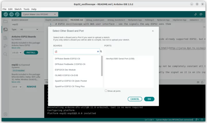


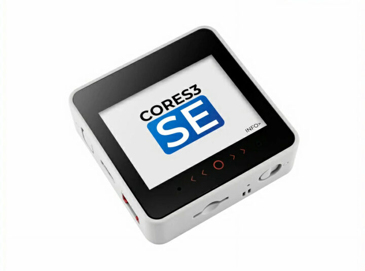


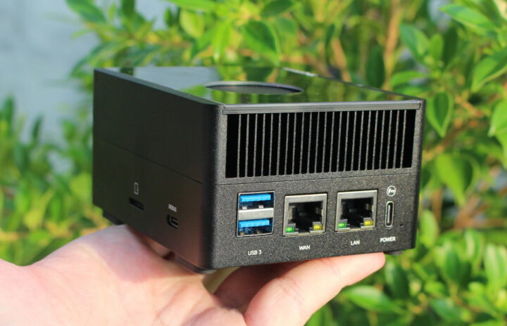


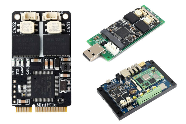


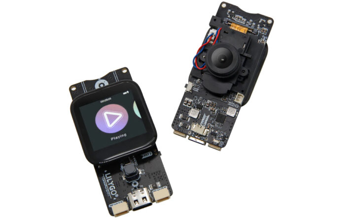


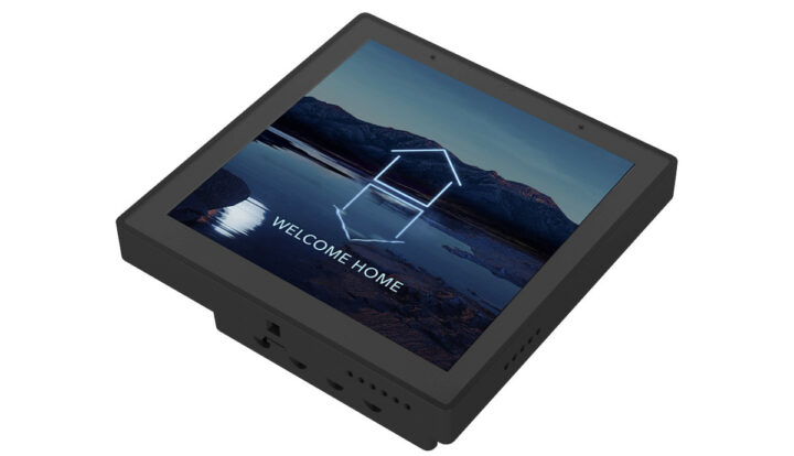


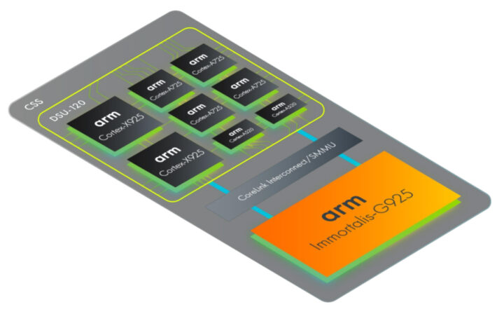


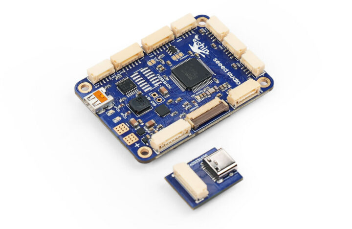


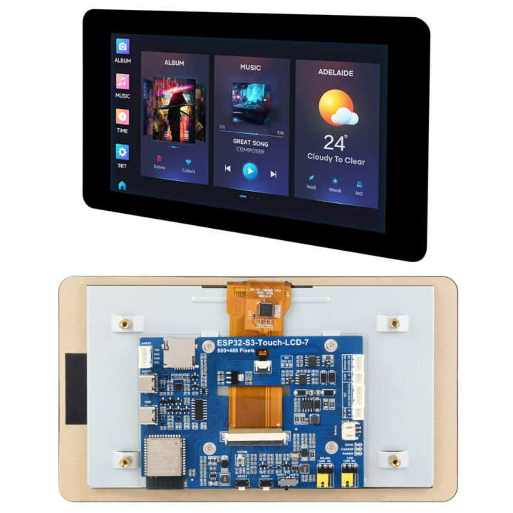


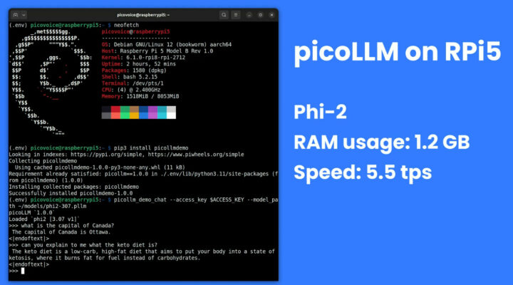


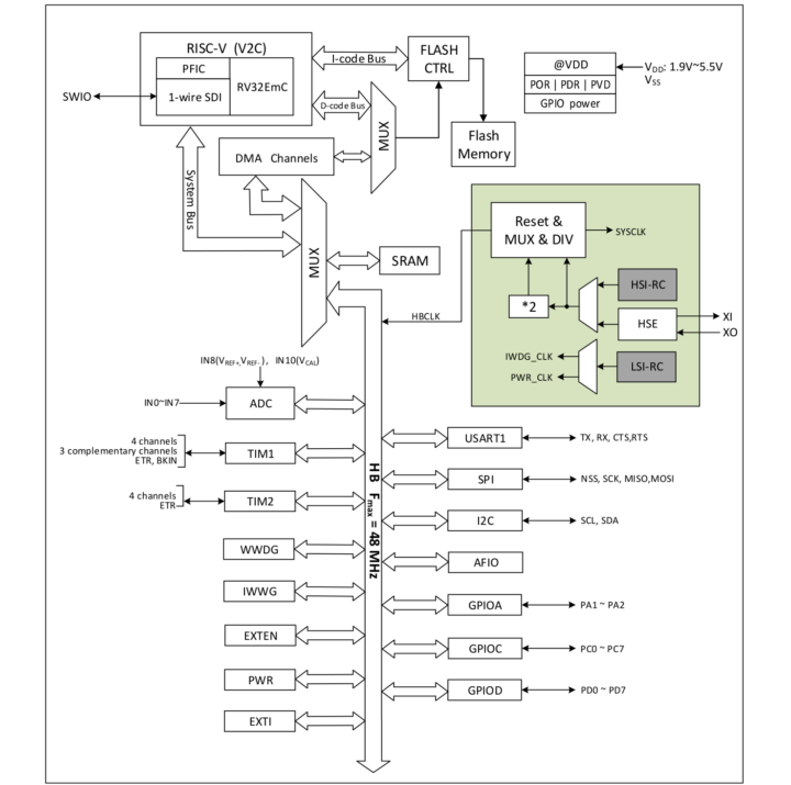


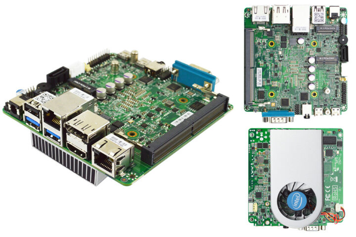


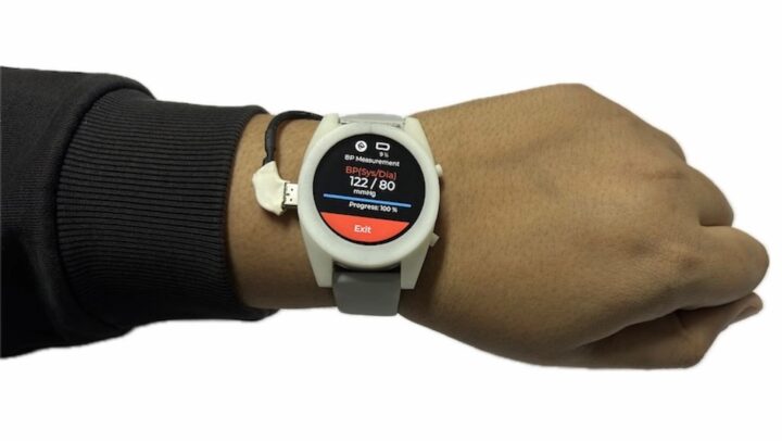


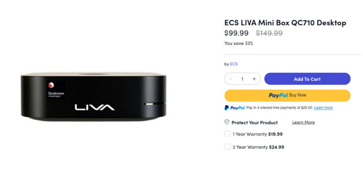


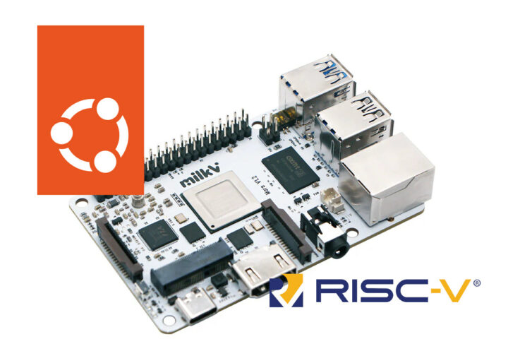


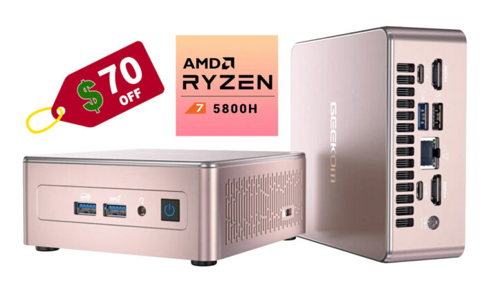


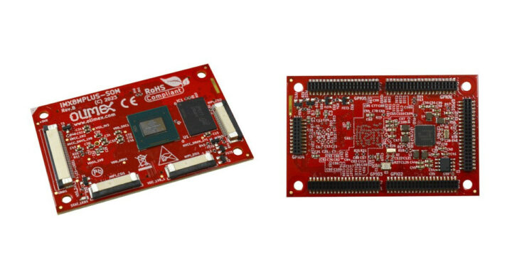


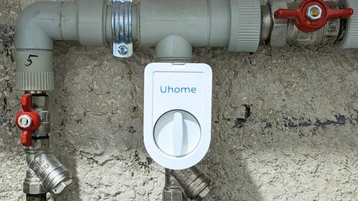


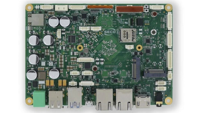


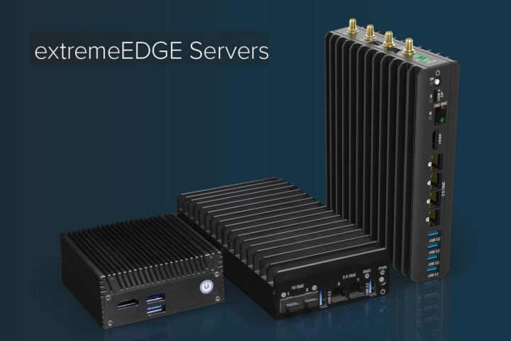


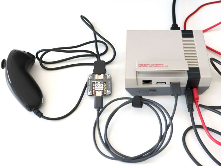


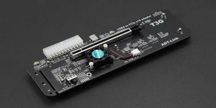


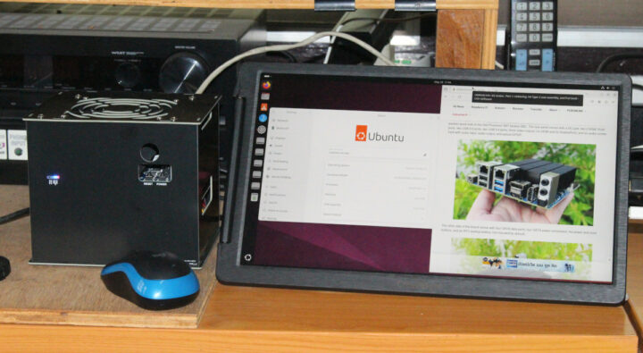


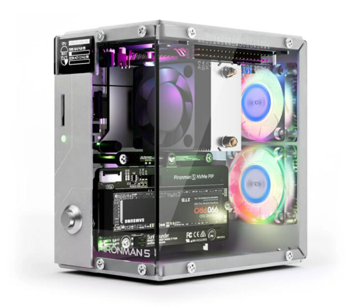


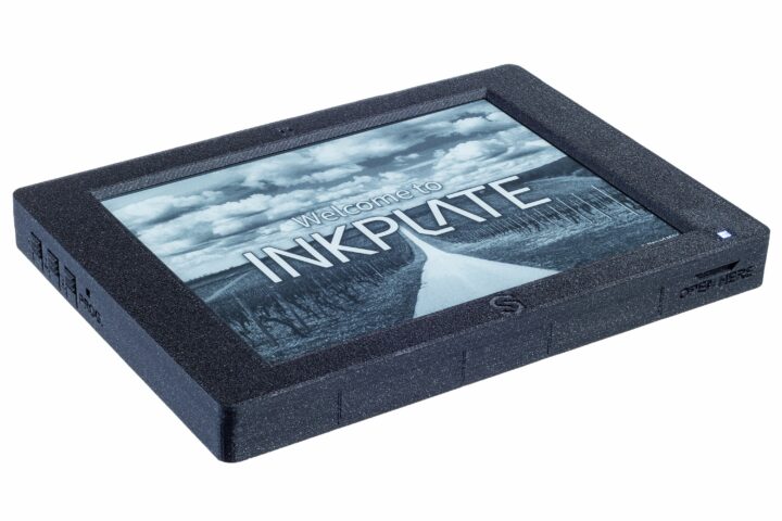


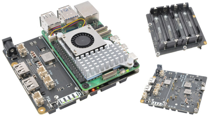


 Cover")
 Unbox")
 Inside1")
 Inside3")
 Specification1")
 Specification2")

 eWeLink1")
 Apple Home1")
 Apple Home2")

 Home Assistant2")