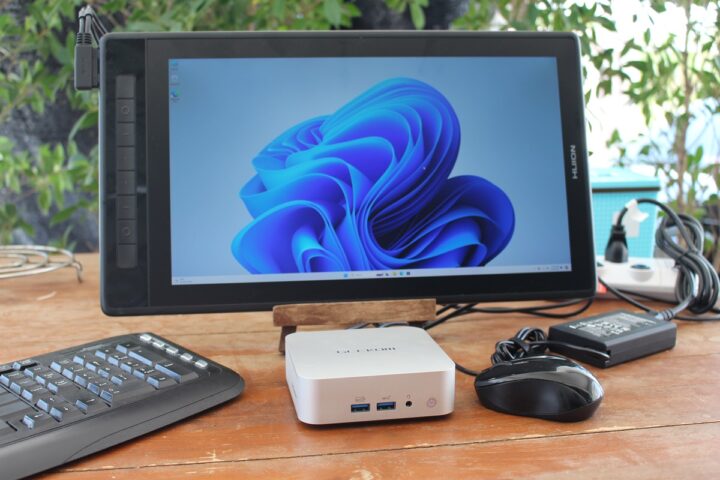
GEEKOM A8 Review – Part 3: Ubuntu 24.04 tested on an AMD Ryzen 8945HS mini PC
We’ve already checked out GEEKOM A8 mini PC hardware with an unboxing and a teardown, before testing the AMD Ryzen 9 8945HS mini PC in Windows 11 Pro, and we’ll now report our experience with the GEEKOM A8 running Ubuntu 24.04 to see how it performs in Linux.
We tested most features of the GEEKOM A8 mini PC on Ubuntu 24.04, ran several benchmarks to compare it to the similar GEEKOM A7 mini PC, performed storage and networking performance testing, ran stress test to check thermal performance, and measured fan noise and power consumption under various conditions.

Installing Ubuntu 24.04 on the GEEKOM A8 mini PC
As usual, we resized the Windows 11 partition to install Ubuntu 24.04 alongside Microsoft OS using a bootable USB flash drive created with the Ubuntu ISO.

But you’ll notice BitLocker is enabled so the Ubuntu 24.04 installation can’t proceed. The installation wizard will ask us to turn off BitLocker for a dual boot system or to wipe out the Windows installation to install Ubuntu only.

We went back to Windows to disable BitLocker drive encryption as shown in the screenshot below.

After this change, the Ubuntu 24.04 installation went smoothly on the GEEKOM A8 mini PC, and we didn’t need to enter the BIOS to change the boot priority as we sometimes had to do in the past. You’ll be presented with the Grub menu at boot to select Ubuntu or Windows.
Ubuntu 24.04 system information
The Settings -> About window confirms we have a GEEKOM A8 running Ubuntu 24.04 LTS on a 16-core AMD Ryzen 9 8945HS processor with AMD Radeon 780M graphics, 32GB of RAM 32GB and 2TB of storage.

We can get a free more details from the command line…
aey@geekom-a8-cnx:~$ cat /etc/lsb-release
DISTRIB_ID=Ubuntu
DISTRIB_RELEASE=24.04
DISTRIB_CODENAME=noble
DISTRIB_DESCRIPTION="Ubuntu 24.04 LTS"
aey@geekom-a8-cnx:~$ uname -a
Linux A8 6.8.0-35-generic #35-Ubuntu SMP PREEMPT_DYNAMIC Mon May 20 15:51:52 UTC 2024 x86_64 x86_64 x86_64 GNU/Linux
aey@geekom-a8-cnx:~$ free -mh
               total        used        free      shared  buff/cache   available
Mem:            30Gi       2.8Gi        27Gi        91Mi       1.1Gi        27Gi
Swap:          8.0Gi          0B       8.0Gi
and even more with inxi utility:
aey@geekom-a8-cnx:~$ inxi -Fc0
System:
  Host: A8 Kernel: 6.8.0-35-generic arch: x86_64 bits: 64
  Desktop: GNOME v: 46.0 Distro: Ubuntu 24.04 LTS (Noble Numbat)
Machine:
  Type: Desktop System: GEEKOM product: A8 v: N/A serial: <superuser required>
  Mobo: N/A model: A8 serial: <superuser required> UEFI: American
    Megatrends LLC. v: 0.45 date: 04/07/2024
CPU:
  Info: 8-core model: AMD Ryzen 9 8945HS w/ Radeon 780M Graphics bits: 64
    type: MT MCP cache: L2: 8 MiB
  Speed (MHz): avg: 3479 min/max: 1600/6844 cores: 1: 4000 2: 1618 3: 4000
    4: 4000 5: 4000 6: 4000 7: 4000 8: 4000 9: 1397 10: 4000 11: 4000 12: 4000
    13: 662 14: 4000 15: 4000 16: 4000
Graphics:
  Device-1: AMD Phoenix3 driver: amdgpu v: kernel
  Display: wayland server: X.Org v: 23.2.6 with: Xwayland v: 23.2.6
    compositor: gnome-shell driver: dri: radeonsi gpu: amdgpu
    resolution: 1920x1080~60Hz
  API: EGL v: 1.5 drivers: radeonsi,swrast
    platforms: wayland,x11,surfaceless,device
  API: OpenGL v: 4.6 compat-v: 4.5 vendor: amd mesa v: 24.0.5-1ubuntu1
    renderer: AMD Radeon Graphics (radeonsi gfx1103_r1 LLVM 17.0.6 DRM 3.57
    6.8.0-35-generic)
Audio:
  Device-1: AMD Rembrandt Radeon High Definition Audio driver: snd_hda_intel
  Device-2: AMD Family 17h/19h HD Audio driver: snd_hda_intel
  API: ALSA v: k6.8.0-35-generic status: kernel-api
  Server-1: PipeWire v: 1.0.5 status: active
Network:
  Device-1: Realtek RTL8125 2.5GbE driver: r8169
  IF: enp1s0 state: down mac: 38:f7:cd:c8:2e:72
  Device-2: MEDIATEK MT7922 802.11ax PCI Express Wireless Network Adapter
    driver: mt7921e
  IF: wlp2s0 state: up mac: 94:bb:43:1a:52:92
Bluetooth:
  Device-1: IMC Networks Wireless_Device driver: btusb type: USB
  Report: hciconfig ID: hci0 rfk-id: 0 state: down
    bt-service: enabled,running rfk-block: hardware: no software: no
    address: 00:00:00:00:00:00
Drives:
  Local Storage: total: 1.82 TiB used: 14.83 GiB (0.8%)
  ID-1: /dev/nvme0n1 vendor: Acer model: SSD N7000 2TB size: 1.82 TiB
Partition:
  ID-1: / size: 912.1 GiB used: 14.75 GiB (1.6%) fs: ext4 dev: /dev/nvme0n1p5
  ID-2: /boot/efi size: 96 MiB used: 78.3 MiB (81.6%) fs: vfat
    dev: /dev/nvme0n1p1
Swap:
  ID-1: swap-1 type: file size: 8 GiB used: 0 KiB (0.0%) file: /swap.img
Sensors:
  System Temperatures: cpu: 53.6 C mobo: 52.0 C gpu: amdgpu temp: 48.0 C
  Fan Speeds (rpm): N/A
Info:
  Memory: total: 32 GiB note: est. available: 30.63 GiB used: 2.82 GiB (9.2%)
  Processes: 358 Uptime: 2h 21m Shell: Bash inxi: 3.3.34
The program lists the AMD Ryzen 9 8945HS processor with 8 cores and 16 threads as expected but Linux reports a maximum speed of 6,844 MHz… against the advertised 5.2 GHz Turbo frequency. Some peripherals include the Realtek RTL8125 2.5GbE controller and MediaTek MT7922 WiFi 6 network adapter. Bluetooth is detected but with a MAC address of 00:00:00:00:00:00, and as we’ll see further below it does not work. The idle CPU temperature is reported to be 53.6°C, but we will check that again.
GEEKOM A8 benchmarks on Ubuntu 24.04
We’ll start benchmarking the AMD Ryzen 9 8945HS mini PC with Thomas Kaiser’s sbc-bench.sh:
aey@geekom-a8-cnx:~/Downloads/sbc-bench-master$ sudo ./sbc-bench.sh -r
Starting to examine hardware/software for review purposes...

sbc-bench v0.9.67

Installing needed tools: apt-get -f -qq -y install gcc make build-essential lm-sensors powercap-utils curl git links mmc-utils smartmontools stress-ng, p7zip 16.02, tinymembench, ramlat, mhz, cpufetch, cpuminer. Done.
Checking cpufreq OPP. Done.
Executing tinymembench. Done.
Executing RAM latency tester. Done.
Executing OpenSSL benchmark. Done.
Executing 7-zip benchmark. Done.
Throttling test: heating up the device, 5 more minutes to wait. Done.
Checking cpufreq OPP again. Done (10 minutes elapsed).

Results validation:

  * Measured clockspeed not lower than advertised max CPU clockspeed
  * No swapping
  * Background activity (%system) OK
  * No throttling

Full results uploaded to https://0x0.st/XboB.bin

# GEEKOM A8  / Ryzen 9 8945HS w/ Radeon 780M Graphics

Tested with sbc-bench v0.9.67 on Thu, 06 Jun 2024 18:45:34 +0700. Full info: [https://0x0.st/XboB.bin](http://0x0.st/XboB.bin)

### General information:

    Information courtesy of cpufetch:

    Name:                AMD Ryzen 9 8945HS w/ Radeon 780M Graphics
    Microarchitecture:   Zen 4
    Technology:          4nm
    Max Frequency:       6.843 GHz
    Cores:               8 cores (16 threads)
    AVX:                 AVX,AVX2,AVX512
    FMA:                 FMA3
    L1i Size:            32KB (256KB Total)
    L1d Size:            32KB (256KB Total)
    L2 Size:             1MB (8MB Total)
    L3 Size:             16MB

    Ryzen 9 8945HS w/ Radeon 780M Graphics, Kernel: x86_64, Userland: amd64

    CPU sysfs topology (clusters, cpufreq members, clockspeeds)
                     cpufreq   min    max
     CPU    cluster  policy   speed  speed   core type
      0        0        0     1600    6844       -
      1        0        1     1600    6844       -
      2        0        2     1600    6844       -
      3        0        3     1600    6844       -
      4        0        4     1600    6844       -
      5        0        5     1600    6844       -
      6        0        6     1600    6844       -
      7        0        7     1600    6844       -
      8        0        8     1600    6844       -
      9        0        9     1600    6844       -
     10        0       10     1600    6844       -
     11        0       11     1600    6844       -
     12        0       12     1600    6844       -
     13        0       13     1600    6844       -
     14        0       14     1600    6844       -
     15        0       15     1600    6844       -

31362 KB available RAM

### Policies (performance vs. idle consumption):

Status of performance related policies found below /sys:

    /sys/module/pcie_aspm/parameters/policy: default [performance] powersave powersupersave

### Clockspeeds (idle vs. heated up):

Before at 54.2°C:

    cpu0:

After at 92.0°C:

    cpu0: OPP: 6843, Measured: 4985     (-27.2%)

### Performance baseline

  * memcpy: 20318.5 MB/s, memchr: 78557.7 MB/s, memset: 62156.7 MB/s
  * 16M latency: 28.89 20.10 29.21 20.17 27.64 30.71 36.28 41.94
  * 128M latency: 99.04 98.41 99.25 98.73 98.85 99.52 104.9 108.8
  * 7-zip MIPS (3 consecutive runs): 69297, 68708, 68364 (68790 avg), single-threaded: 6446
  * `aes-256-cbc    1160880.19k  1344417.81k  1390608.64k  1405969.41k  1418925.40k  1397435.05k`
  * `aes-256-cbc    1177681.15k  1359618.26k  1404829.44k  1417271.98k  1420967.94k  1422136.66k`

### PCIe and storage devices:

  * Realtek RTL8125 2.5GbE: Speed 5GT/s, Width x1, driver in use: r8169,
  * MEDIATEK MT7922 802.11ax PCI Express Wireless Network Adapter: Speed 5GT/s, Width x1, driver in use: mt7921e,
  * O2 SD/MMC Card Reader: Speed 2.5GT/s, Width x1, driver in use: sdhci-pci,
  * AMD Device 15b9: Speed 16GT/s, Width x16, driver in use: xhci_hcd, ASPM Disabled
  * AMD Device 15ba: Speed 16GT/s, Width x16, driver in use: xhci_hcd, ASPM Disabled
  * AMD Device 15c0: Speed 16GT/s, Width x16, driver in use: xhci_hcd, ASPM Disabled
  * AMD Device 15c1: Speed 16GT/s, Width x16, driver in use: xhci_hcd, ASPM Disabled
  * AMD Pink Sardine USB4/Thunderbolt NHI controller #1: Speed 16GT/s, Width x16, driver in use: thunderbolt, ASPM Disabled
  * 1.8TB "Acer SSD N7000 2TB" SSD as /dev/nvme0: Speed 16GT/s, Width x4, 0% worn out, drive temp: 45°C, ASPM Disabled

### Challenging filesystems:

The following partitions are NTFS: nvme0n1p3,nvme0n1p4 -> https://tinyurl.com/mv7wvzct

### Swap configuration:

  * /swap.img on /dev/nvme0n1p5: 8.0G (0K used)

### Software versions:

  * Ubuntu 24.04 LTS (noble)
  * Compiler: /usr/bin/gcc (Ubuntu 13.2.0-23ubuntu4) 13.2.0 / x86_64-linux-gnu
  * OpenSSL 3.0.13, built on 30 Jan 2024 (Library: OpenSSL 3.0.13 30 Jan 2024)

### Kernel info:

  * `/proc/cmdline: BOOT_IMAGE=/boot/vmlinuz-6.8.0-35-generic root=UUID=e2b1df18-cd94-43ee-8c4c-db149064cda7 ro quiet splash vt.handoff=7`
  * Vulnerability Spec rstack overflow:   Mitigation; Safe RET
  * Vulnerability Spec store bypass:      Mitigation; Speculative Store Bypass disabled via prctl
  * Vulnerability Spectre v1:             Mitigation; usercopy/swapgs barriers and __user pointer sanitization
  * Kernel 6.8.0-35-generic / CONFIG_HZ=1000

Waiting for the device to cool down...................................... 49.6°C
The script did not detect any CPU throttling, but the 7-zip benchmark slowly decreases between each run (69,297 points -> 68,708 points -> 68,364 points) pointing to some sort of thermal or power throttling.
Let’s check the power limits with RyzenAdj (Note: we had to disable secure boot for this to work):
aey@geekom-a8-cnx:~/Downloads/RyzenAdj-master/build$ sudo ./ryzenadj -i
CPU Family: Hawk Point
SMU BIOS Interface Version: 14
Version: v0.15.0
PM Table Version: 4c0008
|        Name         |   Value   |     Parameter      |
|---------------------|-----------|--------------------|
| STAPM LIMIT         |    45.000 | stapm-limit        |
| STAPM VALUE         |     1.716 |                    |
| PPT LIMIT FAST      |    65.000 | fast-limit         |
| PPT VALUE FAST      |     6.726 |                    |
| PPT LIMIT SLOW      |    54.000 | slow-limit         |
| PPT VALUE SLOW      |     2.968 |                    |
| StapmTimeConst      |   100.000 | stapm-time         |
| SlowPPTTimeConst    |   100.000 | slow-time          |
| PPT LIMIT APU       |    54.000 | apu-slow-limit     |
| PPT VALUE APU       |       nan |                    |
| TDC LIMIT VDD       |    55.001 | vrm-current        |
| TDC VALUE VDD       |     1.489 |                    |
| TDC LIMIT SOC       |    15.001 | vrmsoc-current     |
| TDC VALUE SOC       |     1.360 |                    |
| EDC LIMIT VDD       |   130.001 | vrmmax-current     |
| EDC VALUE VDD       |    55.895 |                    |
| EDC LIMIT SOC       |    20.001 | vrmsocmax-current  |
| EDC VALUE SOC       |     3.375 |                    |
| THM LIMIT CORE      |    92.001 | tctl-temp          |
| THM VALUE CORE      |    45.931 |                    |
| STT LIMIT APU       |     0.000 | apu-skin-temp      |
| STT VALUE APU       |     0.000 |                    |
| STT LIMIT dGPU      |     0.000 | dgpu-skin-temp     |
| STT VALUE dGPU      |     0.000 |                    |
| CCLK Boost SETPOINT |       nan | power-saving /     |
| CCLK BUSY VALUE     |       nan | max-performance    |
The power limits are as follows:
- Sustained Power Limit (STAPM LIMIT) – 45 Watts
- Actual Power Limit (PPT LIMIT FAST) – 65 Watts
- Average Power Limit (PPT LIMIT SLOW) – 54 Watts
For reference, the AMD Ryzen 9 8945HS CPU has a configurable TDP between 35 and 54W.
We’ll now test the single-core and multi-core CPU performance with Geekbench 6.3.0.

The GEEKOM A8 achieved 2,661 points for the single-core test and 13,275 points for the multi-core test.
We’ll start testing the GPU with Unigine Heaven Benchmark 4.0. The system could render the benchmark at 78.3 FPS on average with a score of 1,972 points at the standard 1920×1080 resolution.

YouTube 4K and 8K video playback was tested with the Chrome browser.

As in most modern mini PCs, YouTube 4Kp30 was played smoothly with only 4 frames dropped out of 12,685 when watching the video for a little over 7 minutes.

8K @ 30 FPS was equally fine with 7 frames dropped out of 12,227.

4K @ 60 FPS is still perfectly watchable, but we got a few more dropped frames (107) out of 25,557 during a 7-minute test.

8K 60 FPS is often hit-or-miss in your review, and the GEEKOM A8 struggled with that one dropping 2,088 frames out of 11,525.
The GEEKOM A8 had no issues playing the same 8K 60 FPS video in Windows 11/Chrome, but the results are about the same as we had with the GEEKOM A7 with Ubuntu 22.04.
We can evaluate web browsing performance with Speedometer 2.0. Let’s start with Firefox.

298 runs per minute in Firefox is quite close to the 315 runs per minute the system achieved in the latest version of Google Chrome.

Since Speedometer 2.0 is getting deprecated, we also tested the mini PC with Speedometer 3.0, again with Firefox (19.1 points) and Chrome (21.2 points).


It’s important to note that web browser benchmark scores tend to increase over time on the same hardware due to software optimizations in web browsers.
Comparison of GEEKOM A8 benchmarks against other mini PCs running Ubuntu 24.04/22.04
We’ll now compare the Ubuntu 24.04 benchmarks on the GEEKOM A8 against other high-end mini PCs namely the GEEKOM A7 (AMD Ryzen 9 7840HS), the GEEKOM XT12 Pro (Intel Core i9-12900H), the GEEKOM Mini IT13 (Intel Core i9-13900H), and the Khadas Mind Premium (Intel Core i7-1360P)
Let’s list the main specifications for the 5 machines first.
| GEEKOM A8 | GEEKOM A7 | GEEKOM XT12 Pro | GEEKOM Mini IT13 | Khadas Mind Premium | |
|---|---|---|---|---|---|
| SoC | AMD Ryzen 9 8945HS | AMD Ryzen 9 7840HS | Intel Core i9-12900H | Intel Core i9-13900H | Intel Core i7-1360P |
| CPU | 8-core/16-thread processor up to 5.2 GHz | 8-core/16-thread processor up to 5.1GHz | 14-core/20-thread (6P+8E) processor up to 5.0 GHz (P-cores), 3.8 GHz (E-Cores) | 14-core/20-Threads (6P+8E) processor up to 5.4 GHz (P-cores), 4.1 GHz (E-Cores) | 12-core/16-core (4P+8E) processor up to 5.0 GHz (P-cores), 3.7 GHz (E-Cores) |
| GPU | AMD Radeon 780M Graphics | AMD Radeon 780M Graphics | 96EU Intel Iris Xe Graphics | 96 EU Intel Iris Xe Graphics | 96 EU Intel Iris Xe Graphics |
| Memory | 32GB DDR5-5600 | 32GB DDR5-5600 | 32GB DDR4-3200 | 32GB DDR4-3200 | 32GB LPDDR5-5200 |
| Storage | 2TB NVMe SSD | 2TB NVMe SSD | 1TB NVMe SSD | 2TB NVMe SSD | 1TB NVMe SSD |
| Default OS | Windows 11 Pro | Windows 11 Pro | Windows 11 Pro | Windows 11 Pro | Windows 11 Home |
And now for the benchmark results.
| GEEKOM A8 | GEEKOM A7 | GEEKOM XT12 Pro | GEEKOM Mini IT13 | Khadas Mind Premium | |
|---|---|---|---|---|---|
| sbc-bench.sh | |||||
| - memcpy | 20,318.5 | 20,406.0 | 22,375.8MB/s | 24,014.4 MB/s (P-core) | 25,389.5 MB/s (P-core) |
| - memset | 62,156.7 | 62,491.7 | 27,398.0MB/s | 26,647.9 MB/s (P-Core) | 24,731.8MB/s (P-core) |
| - 7-zip (average) | 68,790 | 71,110 | 40,190 | 56,540 | 44,430 |
| - 7-zip (top result) | 69,297 | 72,496 | 43,783 | 60,981 | 50,396 |
| - OpenSSL AES-256 16K | 1,422,136.66k | 1,428,559.19k | 1,661,583.36k (P-Core) | 1,844,401.49k (P-Core) | 1,771,334.31k (P-Core) |
| Geekbench 6 Single | 2,661 | 2,535 | 2,575 | 2,745 | 2,093 |
| Geekbench 6 Multi | 13,275 | 12,914 | 10,447 | 11,974 | 8,891 |
| Unigine Heaven score | 1,972 | 2,032 | 1,293 | 1,333 | 1,349 |
| Speedometer 2.0 (Firefox) | 298 | 249 | 298 | 273 | 242 |
As noted in the Windows review, the GEEKOM A8 and A7 are both powerful mini PCs, but there’s almost no difference in terms of performance between the two. AMD Radeon 780M graphics deliver much better graphics performance than Intel Xe graphics, at least up to the 13th Gen family, as Meteor Lake processors are expected to provide a significant boost in 3D graphics performance.
Storage performance and USB ports testing
The internal 2TB NVMe SSD was tested with iozone3 utility:
aey@geekom-a8-cnx:~$ sudo iozone -e -I -a -s 1000M -r 4k -r 16k -r 512k -r 1024k -r 16384k -i 0 -i 1 -i 2

                                                                    random    random      bkwd     record     stride
              kB  reclen    write    rewrite      read    reread      read     write      read    rewrite       read    fwrite  frewrite     fread   freread
         1024000       4    185511    290432    277682    339847     80622    276209
         1024000      16    724156    944924   1010209   1019234    271490    848943
         1024000     512   4539046   4838474   4463116   4526450   3325591   3485303
         1024000    1024   5005621   5053545   4606076   4686778   4167788   4257071
         1024000   16384   5269450   4807261   5936029   6162987   6413054   5271282

iozone test complete.
The performance is excellent with 5,936 MB/s sequential read speed and 5,269 MB/s sequential write speed, although as usual, the results with CrystalDiskMark on Windows are higher at 7,000 MB/s และand 6,262 MB/s respectively.
An EXT-4 partition from ORICO M234C3-U4 “USB4” M.2 NVMe SSD enclosure was used to check the speed of each USB port along with lsusb and iozone3 command line utilities. Here’s the output from the front left USB port:
aey@geekom-a8-cnx:~$ lsusb -t | grep uas
        |__ Port 002: Dev 003, If 0, Class=Mass Storage, Driver=uas, 10000M

aey@geekom-a8-cnx:/media/aey/EXT4-REVIEW$ sudo iozone -e -I -a -s 1000M -r 16384k -i 0 -i 1

                                                                    random    random      bkwd     record     stride
              kB  reclen    write    rewrite      read    reread      read     write      read    rewrite       read    fwrite  frewrite     fread   freread
         1024000   16384    930384    925115    818055    819217

iozone test complete.
The 40 Gbps USB4 port on the left side of the rear panel requires us to use the boltctl utility instead of lsusb since the drive is detected as an NVMe drive:
aey@geekom-a8-cnx:~$ boltctl
● Intel USB4.0 SSD
├─ type: peripheral
├─ name: USB4.0 SSD
├─ vendor: Intel
├─ uuid: ba010000-0052-541e-03d5-47dc2cd4b008
├─ generation: Thunderbolt 3
├─ status: authorized
│ ├─ domain: 41283804-400d-604a-ffff-ffffffffffff
│ ├─ rx speed: 40 Gb/s = 2 lanes * 20 Gb/s
│ ├─ tx speed: 40 Gb/s = 2 lanes * 20 Gb/s
│ └─ authflags: none
├─ authorized: Fri 07 Jun 2024 11:34:42 AM UTC
├─ connected: Fri 07 Jun 2024 11:34:42 AM UTC
└─ stored: Fri 07 Jun 2024 11:34:42 AM UTC
├─ policy: iommu
└─ key: no
aey@geekom-a8-cnx:/media/aey/EXT4-REVIEW$ sudo iozone -e -I -a -s 1000M -r 16384k -i 0 -i 1

                                                                    random    random      bkwd     record     stride
              kB  reclen    write    rewrite      read    reread      read     write      read    rewrite       read    fwrite  frewrite     fread   freread
         1024000   16384   2307500   2306924   2452351   2440168

iozone test complete.
The USB 2.0 port on the rear panel had to be tested with a USB hard drive since the ORICO enclosure is not compatible with USB 2.0 ports:
aey@geekom-a8-cnx:~$ lsusb -t | grep uas
    |__ Port 005: Dev 002, If 0, Class=Mass Storage, Driver=uas, 480M

aey@geekom-a8-cnx:/media/aey/USB3_EXT4$ sudo iozone -e -I -a -s 1000M -r 16384k -i 0 -i 1

                                                                    random    random      bkwd     record     stride
              kB  reclen    write    rewrite      read    reread      read     write      read    rewrite       read    fwrite  frewrite     fread   freread
         1024000   16384     26150     32341     41998     41471

iozone test complete.
Results for the USB ports on GEEKOM A8’s front panel (left to right) in Ubuntu 24.04:
- USB-A #1 – USB 3.2 – 10 Gbps – 818 MB/s read speed, 930 MB/s write speed
- USB-A #2 – USB 3.2 – 10 Gbps – 818 MB/s read speed, 930 MB/s write speed
Same tests for the rear panel (left to right):
- USB-C #1 – Thunderbolt 3/40 Gbps – 2307 MB/s read speed; (The 2452 MB/s write speed should be ignored as it grossly exceeds the advertised speed).
- USB-A #1 (Top) – USB 3.2 – 10 Gbps – 842 MB/s read speed, 947 MB/s write speed
- USB-A #2 (Bottom) – USB 2.0 – 480 Mbps – 42 MB/s read speed, 26 MB/s write speed
- USB-C #2 – USB 3.2 – 10 Gbps – 844 MB/s read speed, 847 MB/s write speed
All USB ports perform as advertised.
2.5GbE and WiFi 6 network performance (plus Bluetooth testing)
We tested 2.5GbE network performance with iperf3 and UP Xtreme i11 Edge mini PC on the other side:
- Download
aey@geekom-a8-cnx:~$ iperf3 -t 60 -c 192.168.31.12 -i 10 -R
Connecting to host 192.168.31.12, port 5201
Reverse mode, remote host 192.168.31.12 is sending
[  5] local 192.168.31.69 port 59146 connected to 192.168.31.12 port 5201
[ ID] Interval           Transfer     Bitrate
[  5]   0.00-10.01  sec  2.74 GBytes  2.35 Gbits/sec
[  5]  10.01-20.01  sec  2.74 GBytes  2.35 Gbits/sec
[  5]  20.01-30.01  sec  2.74 GBytes  2.35 Gbits/sec
[  5]  30.01-40.01  sec  2.74 GBytes  2.35 Gbits/sec
[  5]  40.01-50.01  sec  2.74 GBytes  2.35 Gbits/sec
[  5]  50.01-60.01  sec  2.74 GBytes  2.35 Gbits/sec
- - - - - - - - - - - - - - - - - - - - - - - - -
[ ID] Interval           Transfer     Bitrate         Retr
[  5]   0.00-60.05  sec  16.4 GBytes  2.35 Gbits/sec    0             sender
[  5]   0.00-60.01  sec  16.4 GBytes  2.35 Gbits/sec                  receiver

iperf Done.
- Upload
aey@geekom-a8-cnx:~$ iperf3 -t 60 -c 192.168.31.12 -i 10
Connecting to host 192.168.31.12, port 5201
[  5] local 192.168.31.69 port 45520 connected to 192.168.31.12 port 5201
[ ID] Interval           Transfer     Bitrate         Retr  Cwnd
[  5]   0.00-10.01  sec  2.74 GBytes  2.36 Gbits/sec    0    732 KBytes
[  5]  10.01-20.01  sec  2.74 GBytes  2.35 Gbits/sec    0   1.23 MBytes
[  5]  20.01-30.01  sec  2.74 GBytes  2.35 Gbits/sec    0   1.23 MBytes
[  5]  30.01-40.01  sec  2.74 GBytes  2.35 Gbits/sec    0   1.23 MBytes
[  5]  40.01-50.01  sec  2.74 GBytes  2.35 Gbits/sec    0   1.83 MBytes
[  5]  50.01-60.01  sec  2.74 GBytes  2.35 Gbits/sec    1   1.28 MBytes
- - - - - - - - - - - - - - - - - - - - - - - - -
[ ID] Interval           Transfer     Bitrate         Retr
[  5]   0.00-60.01  sec  16.4 GBytes  2.35 Gbits/sec    1             sender
[  5]   0.00-60.05  sec  16.4 GBytes  2.35 Gbits/sec                  receiver

iperf Done.
- Full-duplex (bidirectional)
aey@geekom-a8-cnx:~$ iperf3 -t 60 -c 192.168.31.12 -i 10 –bidir
Connecting to host 192.168.31.12, port 5201
[  5] local 192.168.31.69 port 35470 connected to 192.168.31.12 port 5201
[ ID] Interval           Transfer     Bitrate         Retr  Cwnd
[  5]   0.00-10.01  sec  2.74 GBytes  2.35 Gbits/sec    0    716 KBytes
[  5]  10.01-20.01  sec  2.74 GBytes  2.35 Gbits/sec    0   1.59 MBytes
[  5]  20.01-30.01  sec  2.74 GBytes  2.35 Gbits/sec  411   1.12 MBytes
[  5]  30.01-40.01  sec  2.74 GBytes  2.35 Gbits/sec    0   1.12 MBytes
[  5]  40.01-50.01  sec  2.74 GBytes  2.35 Gbits/sec    0   1.12 MBytes
[  5]  50.01-60.01  sec  2.74 GBytes  2.35 Gbits/sec    0   1.12 MBytes
- - - - - - - - - - - - - - - - - - - - - - - - -
[ ID] Interval           Transfer     Bitrate         Retr
[  5]   0.00-60.01  sec  16.4 GBytes  2.35 Gbits/sec  411             sender
[  5]   0.00-60.05  sec  16.4 GBytes  2.35 Gbits/sec                  receiver

iperf Done.
No issue here as on most Intel/AMD mini PCs with 2.5GbE ports.
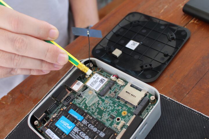
Time to test WiFi 6 in Ubuntu 24.04 on our repaired GEEKOM A8 while connected to a Xiaomi Mi AX6000 router:
- Download
aey@geekom-a8-cnx:~$ iperf3 -t 60 -c 192.168.31.12 -i 10 -R
Connecting to host 192.168.31.12, port 5201
Reverse mode, remote host 192.168.31.12 is sending
[  5] local 192.168.31.59 port 37768 connected to 192.168.31.12 port 5201
[ ID] Interval           Transfer     Bitrate
[  5]   0.00-10.01  sec  1.76 GBytes  1.51 Gbits/sec
[  5]  10.01-20.01  sec  1.77 GBytes  1.52 Gbits/sec
[  5]  20.01-30.01  sec  1.83 GBytes  1.58 Gbits/sec
[  5]  30.01-40.01  sec  1.82 GBytes  1.56 Gbits/sec
[  5]  40.01-50.01  sec  1.88 GBytes  1.61 Gbits/sec
[  5]  50.01-60.01  sec  1.89 GBytes  1.63 Gbits/sec
- - - - - - - - - - - - - - - - - - - - - - - - -
[ ID] Interval           Transfer     Bitrate         Retr
[  5]   0.00-60.05  sec  11.0 GBytes  1.57 Gbits/sec   22             sender
[  5]   0.00-60.01  sec  11.0 GBytes  1.57 Gbits/sec                  receiver

iperf Done.
- Upload
aey@geekom-a8-cnx:~$ iperf3 -t 60 -c 192.168.31.12 -i 10
Connecting to host 192.168.31.12, port 5201
[  5] local 192.168.31.59 port 49128 connected to 192.168.31.12 port 5201
[ ID] Interval           Transfer     Bitrate         Retr  Cwnd
[  5]   0.00-10.01  sec  1.55 GBytes  1.33 Gbits/sec   22   2.36 MBytes
[  5]  10.01-20.01  sec  1.57 GBytes  1.35 Gbits/sec    0   3.01 MBytes
[  5]  20.01-30.01  sec  1.56 GBytes  1.34 Gbits/sec    0   3.01 MBytes
[  5]  30.01-40.01  sec  1.57 GBytes  1.35 Gbits/sec    0   3.01 MBytes
[  5]  40.01-50.01  sec  1.54 GBytes  1.33 Gbits/sec    0   3.01 MBytes
[  5]  50.01-60.01  sec  1.54 GBytes  1.32 Gbits/sec    0   3.01 MBytes
- - - - - - - - - - - - - - - - - - - - - - - - -
[ ID] Interval           Transfer     Bitrate         Retr
[  5]   0.00-60.01  sec  9.34 GBytes  1.34 Gbits/sec   22             sender
[  5]   0.00-60.05  sec  9.34 GBytes  1.34 Gbits/sec                  receiver

iperf Done.
Outstanding WiFi 6 performance with 1.57 Gbps downloads and 1.34 Gbps uploads, one of the best results in our test environment.
What’s not as nice is that Bluetooth 5.3 does not work. GEEKOM keeps releasing mini PCs with MediaTek MT7922 which does not support Bluetooth in Linux.

An error also shows in the kernel log:
aey@geekom-a8-cnx:~$ dmesg | grep -i bluetooth
[    6.751709] Bluetooth: Core ver 2.22
[    6.751731] NET: Registered PF_BLUETOOTH protocol family
[    6.751733] Bluetooth: HCI device and connection manager initialized
[    6.751736] Bluetooth: HCI socket layer initialized
[    6.751738] Bluetooth: L2CAP socket layer initialized
[    6.751741] Bluetooth: SCO socket layer initialized
[    8.273704] Bluetooth: BNEP (Ethernet Emulation) ver 1.3
[    8.273709] Bluetooth: BNEP filters: protocol multicast
[    8.273715] Bluetooth: BNEP socket layer initialized
[    8.869373] Bluetooth: hci0: Opcode 0x0c03 failed: -110
But there’s hope, as Ian Morrison submitted a patch to the Linux kernel mailing list last March, and it might be released as part of Linux 6.10. So if you absolutely need Bluetooth, you could always try to build the Linux kernel manually with this patch. But that’s out of the scope of this review…
Stress test and thermal performance
We ran a stress test on the 16 threads of the AMD Ryzen 9 8945HS processor to evaluate thermal performance by monitoring the CPU temperature with psensor and the CPU frequency with the sbc-bench.sh script.

The frequency quickly stabilized at 4000 MHz (base frequency) and the CPU temperature at 92°C with the fan rotating at max speed. The maximum temperature was quickly reached as shown when looking at the sbc-bench.sh -m command when starting the test.

Fan noise
The GEEKOM A8 is not too noisy at idle or under light loads but it’s quite noisy under heavier loads We measured the fan noise with a sound level meter placed at around 5 centimeters from the top of the enclosure:
- Idle – 38.3 – 39.2 dBA
- YouTube 8Kp60 video in Chrome – 54.0 – 57.1 dBA
- Stress test on all 16 threads – 46.6 – 58.0 dBA
For reference, the meter measures around 37 – 38 dBA in a quiet room. The GEEKOM A8 appears to be quieter at idle (the fan does not rotate or very slow), but noisier under heavy loads compared to the GEEKOM A7.
GEEKOM A8 power consumption in Ubuntu 24.04
We measured the power consumption with a wall power meter:
- Power off – 1.5 Watt
- Idle – 4.3 – 4.9 Watts
- Video playback – 61.3 – 67.8 Watts (Youtube 8K 60fps in Chrome)
- CPU stress test (stress -c 16)
- First 30 seconds – 60.1 – 70.4 Watts
- Longer run – 54.5 – 59.0 Watts
During the measurements, the mini PC was connected to WiFi 6, one RF dongle for a keyboard, one USB mouse, and a CrowVi portable display connected to HDMI and its own power adapter. The power draw with the stress test does not evolve as much under load as with the GEEKOM A7 whose power draw would further drop after a few minutes, and then more after 12 minutes.
Conclusion
The GEEKOM A8 is one of the most powerful mini PCs reviewed on CNX Software (together with GEEKOM A7) and we’ve found it to work well in Ubuntu 24.04 except for Bluetooth not working due to drivers issues with the MediaTek MT7922 wireless module (Azurewave AW-XB591NF). That’s something that might be fixed something next month with a new Linux kernel release. The good news is that the WiFi 6 issues we had with the GEEKOM A7 on Ubuntu 22.04 (with the same module) are all gone in Ubuntu 24.04.
Apart from the Bluetooth issue, the AMD Ryzen 9 8945HS mini PC is great in Linux with fast NVMe storage, excellent multi-core performance, and YouTube video playback works well up to 4K 60 FPS and 8K 30 FPS. Sadly the 8K 60 FPS YouTube video we tried did not play smoothly possibly because of the high room temperature (28°C). The mini PC’s fan is relatively quiet most of the time but gets quite noisy under load. One downside for the GEEKOM A8 is that the GEEKOM A7’s features, performance, and price are all in the same range, so I’m not convinced it brings anything new (apart from a different CPU and cooling system) even if it’s technically a new mini PC…
We’d like to thank GEEKOM for sending us the A8 mini PC for review with an AMD Ryzen 9 8945HS, 32GB DDR5, and a 2 TB SSD. The model reviewed here can be purchased on Amazon for $806.55 with coupon code CNXSWGA8, and you’ll also find it on the GEEKOM US and GEEKOM UK stores with similar pricing when using the discount coupon CNXA8 for a 5% discount. The coupon codes are valid until July 10, 2024. A cheaper GEEKOM A8 model based on the Ryzen 7 8845HS CPU is also available.
CNXSoft: This article is a translation – with some additional insights – of the original review on CNX Software Thailand by Suthinee Kerdkaew.
The post GEEKOM A8 Review – Part 3: Ubuntu 24.04 tested on an AMD Ryzen 8945HS mini PC appeared first on CNX Software - Embedded Systems News.