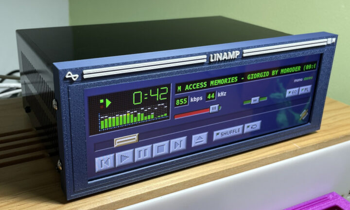
Linamp is a media player box based on Raspberry Pi 4 SBC and a touchscreen display with a GUI that replicates the popular Winamp media player’s GUI that older readers may remember from the late 90s and early 2000s when it was one of the most popular music players for Windows.
Rodmg found some renders of what a real Winamp player could look like online, and it inspired him to create his own. As its name implies Linamp runs on Linux (DietPi) instead of Windows, and the hardware is based on a Raspb
Linamp is a media player box based on Raspberry Pi 4 SBC and a touchscreen display with a GUI that replicates the popular Winamp media player’s GUI that older readers may remember from the late 90s and early 2000s when it was one of the most popular music players for Windows.
Rodmg found some renders of what a real Winamp player could look like online, and it inspired him to create his own. As its name implies Linamp runs on Linux (DietPi) instead of Windows, and the hardware is based on a Raspberry Pi 4, a 7.9-inch touchscreen display, a USB DAC, and various connectors and cables, all housed in a custom-designed metal enclosure and a 3D-printed front cover both designed with Onshape.
Here’s the complete list of off-the-shelf items used for the build:
SBC – Raspberry Pi 4 with a 32 GB microSD card, a set of passive heat sinks, and the bottom part of a Raspberry Pi case
Display – 7.9-inch ultrawide display connected via HDMI and USB, the latter being used for power and touch input
Extension cable for the Raspberry Pi 4’s USB-C port
Push button connected to the Raspberry Pi GPIO for power on/off
Fully assembled kit before closing the box
On the software side, the system runs Dietpi lightweight Linux distribution based on Debian 12 Bookworm. A custom Qt 6 app with Qt Widgets and Audacious code used for the spectrum analyzer was written in C++ to reproduce the look and feel of the original Winamp player. The code has not been made open-source yet, but I understand the plan is to make the project fully open-source. The first photo above already looks neat, but you may be even more impressed after watching the video.
The project’s Hackaday.io page has more details and says the following works in Linamp:
MP3, m4a, FLAC, etc. audio playback from local file systems or SAMBA mounts.
Playlist management for file playback
Real-time bar spectrum analyzer
Track information display including bitrate and sample rate
Volume and balance control
CD Playback (when connecting an external CD drive), including getting the track information from MusicBrainz
Bluetooth and Spotify playback are also being worked on.
I can already hear some say “Just take my money!”, but right now it’s not available. It’s not even possible to build your own as the 3D file and source code for the program are yet to be released. Once/if it is released you should be able to build one yourself. Alternatively, Rodmg has published an interest survey on Google Docs, and if enough people are interested he may start selling the Linamp system either as a kit or a fully assembled system.
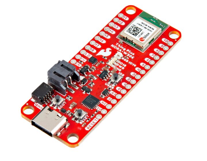
SparkFun Thing Plus – NORA-W306, is a dual-core, dual-band WiFi 4 and BLE 5.3 microcontroller board in the AdaFruit Feather form factor based on the u-box NORA-W306 module and targeted at low-power wireless applications.
The u-blox module integrates the Realtek RTL8720DF chip, a dual-core ARM Cortex-M33 and Cortex-M23 microcontroller with dual-band Wi-Fi (2.4GHz and 5GHz) and Bluetooth 5.3 Low Energy. It offers up to 4MB of encrypted flash and has an onboard PCB antenna. It’s very similar to th
SparkFun Thing Plus – NORA-W306, is a dual-core, dual-band WiFi 4 and BLE 5.3 microcontroller board in the AdaFruit Feather form factor based on the u-box NORA-W306 module and targeted at low-power wireless applications.
The u-blox module integrates the Realtek RTL8720DF chip, a dual-core ARM Cortex-M33 and Cortex-M23 microcontroller with dual-band Wi-Fi (2.4GHz and 5GHz) and Bluetooth 5.3 Low Energy. It offers up to 4MB of encrypted flash and has an onboard PCB antenna. It’s very similar to the RealTek RTL8720DN we covered a few times in the past, but comes with embedded flash.
The SparkFun Thing Plus – NORA-W306 board features a USB-C connector for programming, data, and power. The USB data lines are protected against electrostatic discharge and are connected to a CP2102N USB-to-serial converter for uploading code or serial. This board includes a 2-pin JST-style connector for a LiPo battery, a single-cell charger, and a LiPo fuel gauge for remote applications.
Dual-band Wi-Fi 4 (802.11a/b/g/n), 2.4GHz and 5GHz frequency bands, WPA2/WPA3 authentication
Bluetooth 5.3 Low Energy, 2.4GHz, Secure connection pairing
Built-in PCB antenna
Storage – microSD card slot
USB – 1x USB-C port connected to CP2102N USB-to-Serial Converter
Expansion
4-pin Qwiic connector
20x GPIO via through holes
Up to 20x Interrupts
Up to 3x 12-bit ADC
Up to 12x PWM
Up to 2x UARTs
Up to 2x SPI
Up to 1x I2C
Misc – Buttons (User, Reset, Boot), LEDs (3.3V, Charger, Status, WS2812-2020 addressable RGB LED), 9x jumpers at the back of the board
Power Supply
5V via USB-C
2-pin JST connector for LiPo battery (not included)
MCP73831 single-cell, LiPo charge IC with 500mA default charge rate
MAX17048 single-cell LiPo fuel gauge
XC6222 3.3V/700mA Voltage Regulator
2.2kΩ I2C Pull-Up Resistors
Dimensions – 58.42mm x 22.86mm (Adafruit Feather form factor) with four mounting holes and 30 plated through holes (PTHs)
It is suitable for IoT applications, particularly projects that require remote, low-power operation. It supports the Arduino IDE using the Realtek Arduino core. Like most SparkFun products, the NORA-W306 is open-source, with schematics, Gerber files, tutorials, and other documentation published on GitHub.
The SparkFun Thing Plus – NORA-W306 development board is available for around $40, with discounts for bulk purchases. It adds to other members from the Thing Plus family such as the Thing Plus RA6M5 and the Thing Plus Matter boards.
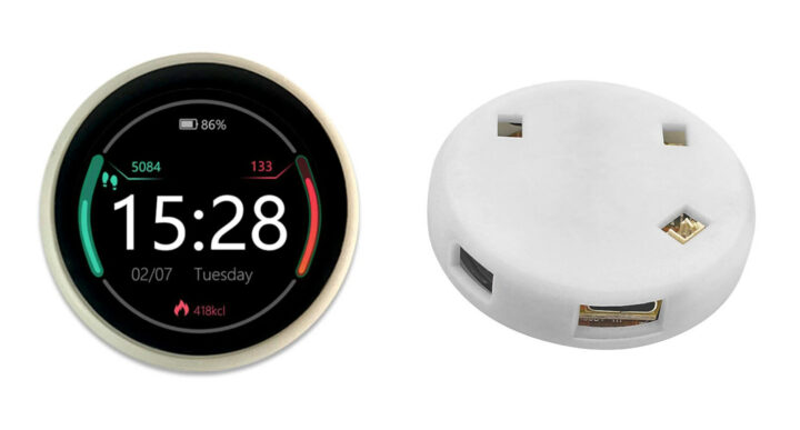
The ESP32-2424S012 is an ESP32-C3 WiFi and BLE development board with a 1.28-inch round touchscreen color display that is fully housed in a black or white plastic enclosure and suitable for Arduino and LVGL library. As we’ll see further below some have also used it with Tasmota and ESPHome firmware.
We previously covered several tiny ESP32-S3/ESP32-C3 boards with a round display such as the LILYGO T-RGB ESP32-S3 board, Makerfabs “ESP32-S3 Round SPI TFT with Touch 1.28″, SB Components’ Dual Round
The ESP32-2424S012 is an ESP32-C3 WiFi and BLE development board with a 1.28-inch round touchscreen color display that is fully housed in a black or white plastic enclosure and suitable for Arduino and LVGL library. As we’ll see further below some have also used it with Tasmota and ESPHome firmware.
We previously covered several tiny ESP32-S3/ESP32-C3 boards with a round display such as the LILYGO T-RGB ESP32-S3 board, Makerfabs “ESP32-S3 Round SPI TFT with Touch 1.28″, SB Components’ Dual Roundy, but they either don’t come with a case at all, or only the front is covered, but the bottom is laid bare. The ESP32-2424S012 is quite similar, but it can be purchased with a case that covers both the front and back with some openings for expansion connectors.
ESP32-2424S012 board specifications:
Wireless module – Espressif Systems ESP32-C3-MINI-1U module
Display – 1.28-inch round IPS LCD screen with 16-bit color, 240×240 resolution; based on GC9A01 controller; optional touchscreen (CST816D)
USB – 1x USB Type-C port for power and programming
Expansion – 4-pin JST-1.0 UART connector
Misc – Reset and Button buttons; on/off switch
Power Supply
5V via USB-C port
2-pin JST-1.25 connector for battery
Dimensions
38.5 x 37 mm (without case)
About 42mm ∅ with case
Weight – About 20 grams
We’re provided with a zip file (note: your browser may issue a security warning due to the use of HTTP instead of HTTPS) with Arduino sample code, specifications, photos, some datasheet, a user manual to use the board with the Arduino IDE, some tools, and flashing instructions.
But I’ve noticed the board is not new and started to appear about a year ago, with people wanting to use it with Tasmota or ESPHome/Home Assistant. GitHub also has 5 projects for the ESP32-2424S012 board. I’ve embedded a short video that uses the board as a media player controller with ESPHome.
There are three/four variants of the board:
Board with no touchscreen and no case
Board with white or black case, but not touchscreen
Board with white or black case and touchscreen
I first found the ESP32-2424S012 ESP32-C3 round display on Banggood where it is sold for $14.93 to $20.78, but it’s also available on AliExpress for slightly lower prices. The M5Dial is another alternative with an ESP32-S3, a 1.28-inch round touchscreen display, and a fully enclosed design, but it’s thicker and more expensive because it’s also a knob/rotary encoder.
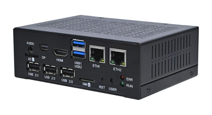
MYiR MYD-LR3568-GK-B is a fanless industrial PC Box powered by Rockchip RK3568 quad-core Cortex-A55 Ai SoC with up to 4GB RAM, 32GB GB eMMC flash, support for M.2 NVMe storage, and communication interfaces such as RS232, RS485, and CAN Bus.
The device also offers dual gigabit Ethernet and optional WiFI, BLE, and 4G LTE connectivity, two video outputs, and five USB ports with a set of features and capabilities that makes it suitable for edge AI, video analytics, industrial control, protocol conv
MYiR MYD-LR3568-GK-B is a fanless industrial PC Box powered by Rockchip RK3568 quad-core Cortex-A55 Ai SoC with up to 4GB RAM, 32GB GB eMMC flash, support for M.2 NVMe storage, and communication interfaces such as RS232, RS485, and CAN Bus.
The device also offers dual gigabit Ethernet and optional WiFI, BLE, and 4G LTE connectivity, two video outputs, and five USB ports with a set of features and capabilities that makes it suitable for edge AI, video analytics, industrial control, protocol conversion, communication management, and more.
CPU – Quad-core Cortex-A55 processor at up to 1.4 GHz (An “overdrive” version at 1.8 GHz is available upon request)
GPU – Mali G52 2EE GPU with support for OpenGL ES 1.1/2.0/3.2, OpenCL 2.0, Vulkan 1.1
VPU
4Kp60 H.264, H.265, VP9, 1080p60 MPEG-4/-2/-1, VP8, and VC1 video decoder
1080p60 H.264/H.265 video encoder
AI accelerator – Up to 1 TOPS NPU
System Memory – 2GB or 4GB LPDDR4
Storage
16GB or 32GB eMMC flash
32KB EEPROM
M.2 NVMe SSD PCIe slot (2280)
MicroSD card socket
Video Output
HDMI 2.0 up to 1080p60 (by default)
Mini DisplayPort (DP) up to 1080p60 (by default)
Audio – 3.5mm microphone/earphone jack
Networking and Wireless
2x Gigabit Ethernet RJ45 ports
WiFi 5 and Bluetooth 5.2 module with WiFi/BT antenna interface
Optional 4G LTE module via M.2 (USB) socket and externally accessible SIM card holder
USB
2x USB 3.0 host ports
3x USB 2.0 Type-A ports
Serial
1x RS232 via terminal block
2x RS485 via terminal block
2x CAN Bus via terminal block
Debugging – USB-UART USB Type-C debug interface
Misc
Reset button, user button
RUN status LED, ERR user LED
Power Supply – +12V/2A via 3-pole Phoenix terminal
Dimensions
130 x 93.5 x 44mm without mounting bracket
160 x 93.5 x 44mm with mounting bracket
Weight – TBD
Temperature Range – -40°C to 85°C (-30°C to 85°C with wireless module)
Operating Humidity – 5 to 95%, non-condensing
MYIR provides SDKs for both Linux and Debian operating systems that boot, kernel, driver source code, and related development tools, along with “detailed documentation” to ease the development process. As usual with MYiR, none of that documentation is available publicly, and the company only shares it with paying customers.
The top layer of the front panel exposes the interfaces from the MYIR MYD-LR3568 development board we covered last month, and the other interfaces are made available through the company’s MY-ICEB001 expansion board.
A good thing with MYiR Tech is that they provide pricing publicly and allow customers to buy samples online, something that cannot be said of many B2B companies. The MYD-LR3568-GK-B RK3568 industrial PC is offered for $159 in 2GB/16GB configuration and $189 in 4GB/32GB configuration, while a kit without case goes for $139 More details and purchase links can be found on the product page. Additional information may also be available in the short announcement.
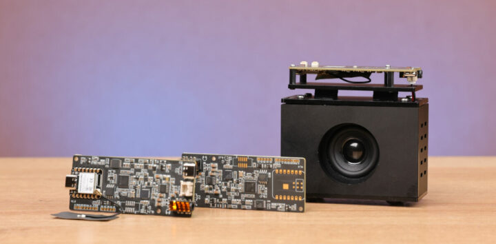
The DAB Embedded CAMKIT-AML302-IMX462, is a compact AI camera kit built around the Amlogic C302X processor with 256MB DDR3 on-chip (SiP) and designed for image processing and machine learning applications. The board also includes GMSL2 interfaces that add support for a range of Sony camera sensors, including global shutter and 3D options. Additionally, it has 100Mbit LAN, Wi-Fi, BLE, and CAN bus connectivity which makes this board useful for various computer vision applications.
Previously we ha
The DAB Embedded CAMKIT-AML302-IMX462, is a compact AI camera kit built around the Amlogic C302X processor with 256MB DDR3 on-chip (SiP) and designed for image processing and machine learning applications. The board also includes GMSL2 interfaces that add support for a range of Sony camera sensors, including global shutter and 3D options. Additionally, it has 100Mbit LAN, Wi-Fi, BLE, and CAN bus connectivity which makes this board useful for various computer vision applications.
USB – Micro USB port for programming and debugging
Serial – CAN 2.0b (+ CAN FD)
Power – 12V DC input
Operating Temperature – -20°C to +70°C
DAB Embedded CAMKIT-AML302-IMX462 Block Diagram
The Amlogic C302X board does not feature an audio out port or a 3.5mm jack that we are used to seeing on most development boards, instead, the audio is transmitted via the GMSL2 connectors that not only transmit video signals it also enables bidirectional audio transmission over the same coaxial cable or shielded twisted pair cable as the video signal.
In terms of software, the device runs a custom Linux 5.15.78 operating system built with Buildroot and also offers a Fastboot interface for advanced configuration and flashing. Additional software includes BlueZ for Bluetooth Low Energy connectivity, Wi-Fi, and an SDK with OpenCV hardware acceleration for image processing and NN API for neural network tasks like face recognition. However, the company doesn’t have anything remotely related to the camera kit on its GitHub account.
The camera kit is priced at €650 (approximately $710), but the company does not have an official online store. To order, you need to email them; More details can be found on the product page, where you’ll also find a product brief.
Seeed Studio’s ReSpeaker Lite Series includes the ReSpeaker Lite 2-Mic Array and Voice Assistant Kit, featuring the XMOS XU-316 AI sound chip for advanced voice processing and integration with Home Assistant via ESPHome. It’s perfect for smart home control with far-field voice capture and noise cancellation.
The kit combines the ReSpeaker Lite dual-microphone array with the XIAO ESP32S3 module for voice recognition, noise reduction, and processing. It supports WiFi, BLE 5.0, and has a 2.4GHz rod
Seeed Studio’s ReSpeaker Lite Series includes the ReSpeaker Lite 2-Mic Array and Voice Assistant Kit, featuring the XMOS XU-316 AI sound chip for advanced voice processing and integration with Home Assistant via ESPHome. It’s perfect for smart home control with far-field voice capture and noise cancellation.
The kit combines the ReSpeaker Lite dual-microphone array with the XIAO ESP32S3 module for voice recognition, noise reduction, and processing. It supports WiFi, BLE 5.0, and has a 2.4GHz rod antenna. It also offers I2S and USB connectivity for use with microcontrollers and SBCs, making it ideal for smart voice assistants and home automation.
We’ve previously covered the NXP i.MX RT106F & RT106A/L, where NXP i.MX RT106A can run voice assistant software with features like acoustic echo cancellation, ambient noise reduction, beamforming, barge-in, and playback processing. We’ve also written about other ReSpeaker boards, such as the ReSpeaker 4-Mic Array board, ReSpeaker Core board, and ReSpeaker Core v2. Feel free to check if you are interested in this product.
Automatic Speech Recognition Algorithms – Interference Cancellation, Acoustic Echo Cancellation, Noise Suppression, Voice-to-Noise Ratio (VNR), and Automatic Gain Control (AGC)
Microphone – 2x Digital PDM MEMS microphones
Sensitivity – -26 dBFS
Acoustic Overload Point – 120 dBL
SNR – 64 dBA
Far-Field Voice Capture – Up to 3m with Advanced noise-cancellation
Speaker – Mono Enclosed Speaker
Input Power – 5W
Impedance – 4ohm±15%
Output S.P.L – 88±3dB
Distortion – 10% Max
Frequency Range – FO—-20kHz
Resonant Frequency – Fb: 125Hz ±20% and Fo: 500Hz ±20%
Audio Output – Speaker Connector and 3.5mm Headphone Jack
USB – USB Type-C Port for power and data transmission.
Interfaces – I2S and USB
Misc
Programmable WS2812 RGB LED provides visual feedback
Power LED and Mute LED
Buttons for User and Mute
Power Supply – 5V via Type-C USB port or external 5V
Dimensions – 95 x 92 x 42mm (Full kit)
ReSpeaker Lite board
ReSpeaker Lite Voice Assistant Kit integrates with Home Assistant via ESPHome firmware, supports Amazon Alexa and Google Assistant, and is compatible with Arduino, PlatformIO, MicroPython, and CircuitPython. The kit supports custom firmware updates via DFU-Util and offers I2S and USB connections for use with MCUs, SBCs, and PCs like Raspberry Pi. You’ll find a getting-started guide and can explore various testing and applications such as I2S Test, Streams Generator, CSV Converter, MP3 Player, Keyword Spotting, and MQTT Audio Streaming on the wiki. The guides also include instructions for building a Voice Assistant for Home Assistant using custom wake words.
Node-RED MQTT audio streaming and Home Assistant integration
The ReSpeaker Voice Assistant Kit with 5W speaker and black acrylic enclosure is now available for $33.91 on the Seeed Studio store, and you’ll find the ReSpeaker Lite board only for $24.90 and the ReSpeaker Voice Assistant Kit for $29.91 on the same page.
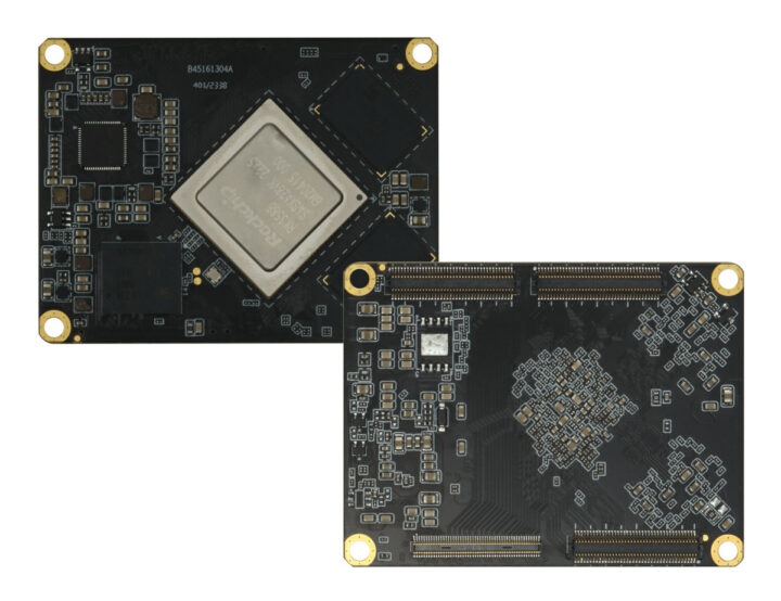
Dusun DSOM-042R is a system-on-module based on Rockchip RK3588M automotive-grade AI SoC with 8GB RAM and 128GB eMMC flash, capable of operating in the -40°C to 85°C temperature range, and fitted with four high-density connected exposes the many interfaces from the octa-core Cortex-A76/A55 processor.
We first found out about the RK3588M SoC last year with the Firefly AIO-3588MQ board also comprised of a system-on-module and carrier board with support for up to sixteen cameras and up to six Full H
Dusun DSOM-042R is a system-on-module based on Rockchip RK3588M automotive-grade AI SoC with 8GB RAM and 128GB eMMC flash, capable of operating in the -40°C to 85°C temperature range, and fitted with four high-density connected exposes the many interfaces from the octa-core Cortex-A76/A55 processor.
We first found out about the RK3588M SoC last year with the Firefly AIO-3588MQ board also comprised of a system-on-module and carrier board with support for up to sixteen cameras and up to six Full HD displays to drive the car dashboard, in-vehicle infotainment, a digital rearview mirror, headrest monitors, ADAS system, and more. We hadn’t noticed other manufacturers launch a product with the automotive-grade RK3588M, and the DusunIoT DSOM-042R offers another option.
Dusun RK3588M SoM specifications:
SoC – Rockchip RK3588M octa-core processor with
CPU – 4x Cortex-A76 cores @ up to 2.1 GHz, 4x Cortex-A55 cores @ up to 1.7 GHz (frequencies TBC)
GPU – Arm Mali-G610 MP4 GPU with OpenGL ES 3.2, OpenCL 2.2, Vulkan 1.1 support
NPU – 6 TOPS AI accelerator
VPU
Video decoding:
8Kp60 H.265/VP9/AVS2
8Kp30 H.264 AVC/MVC
4Kp60 AV1
1080p60 MPEG-2/-1/VC-1/VP8
Video encoding – 8Kp30 H.265 / H.264
Up to 32-channel 1080p30 decoding and 16-channel 1080p30 encoding can be achieved.
System Memory – 8GB RAM
Storage – 128GB eMMC flash
1x 100-pin B2B connectors, 3x 80-pin B2B connectors with
Storage – 3x SATA 3.0, 1x SDMMC, PCIe interfaces (see high-speed interfaces)
Video Output
HDMI 2.1 up to 8Kp60 or 4Kp120
HDMI 2.0 up to 4Kp60
2x MIPI DSI display interfaces up to 4Kp60
2x DisplayPort 1.4 up to 8Kp30fps (multiplexed with USB 3.0)
2x eDP1.3 connector up to 4Kp60
BT.1120 up to 1080p60
Up to seven displays supported
Video Input
1x 4-lane MIPI CSI or 2x 2-lane MIPI CSI
2x MIPI DC (4-channel DPHY v2.0 or 3-channel CPHY V1.1)
Temperature Range – Operating: -40°C to 85°C; storage: -40°C to 105°C in the board’s datasheet
Humidity – 10% to 80 % (non-condensing)
The product page mentions support for Android 11 and Ubuntu 18.04 operating systems, but when asked to confirm that, the company replies that Android 12.0, Ubuntu Desktop and Server, Debian 11, and buildroot RTLinux can be supported.
The same product page documents all I/Os from the board-to-board connector, but apart from that it is light on detail and lacks any information about a reference carrier board, so I asked. I was first told customers can evaluate the module with the DSGW-380 carrier board for gateways pictured below.
But it’s obvious that carrier board is better suited to the Rockchip RK3588 version of the module, as it does not offer any camera interfaces and only two HDMI output ports, so it’s not optimal for advanced automotive applications requiring multiple cameras for ADAS and several displays for the dashboard and infotainment.
After I pointed this out to the company, they explained they mainly offer “SOM secondary development and mainboard ODM services” and “can design the carrier board according to the requirements”. So it looks like that may not have an evaluation carrier board for automotive applications, and it would have to be designed by the customer or by contracting Dusun. Existing carrier boards such as the one above can be used to test other functions of the Rockchip RK3588M system-on-module.
Pricing and availability information are not provided due to the custom nature of the design, and interested parties would have to contact the company to discuss the project in detail.
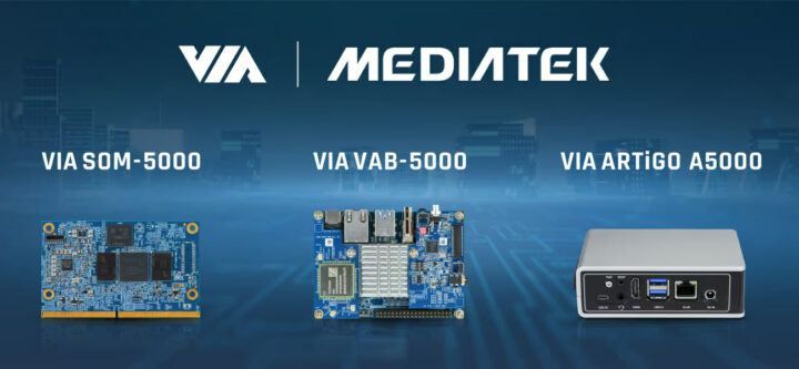
VIA Technologies has launched three new Edge AI solutions based on the MediaTek Genio 700 mid-range Cortex-A78/A55 AI SoC with the SOM-5000 SMARC 2.1.1 system-on-module, VAB-5000 single board computer (SBC), and ARTiGO A5000 fanless embedded system.
All three platforms come with 4GB or 8GB LPDDR4 memory, 16GB eMMC flash, gigabit Ethernet, video interfaces, and camera inputs, and are designed for intelligent edge computing across a range of industrial, commercial, and consumer applications.
VIA
VIA Technologies has launched three new Edge AI solutions based on the MediaTek Genio 700 mid-range Cortex-A78/A55 AI SoC with the SOM-5000 SMARC 2.1.1 system-on-module, VAB-5000 single board computer (SBC), and ARTiGO A5000 fanless embedded system.
All three platforms come with 4GB or 8GB LPDDR4 memory, 16GB eMMC flash, gigabit Ethernet, video interfaces, and camera inputs, and are designed for intelligent edge computing across a range of industrial, commercial, and consumer applications.
VIA SOM-5000 system-on-module
Specifications:
SoC – MediaTek Genio 700 (MT8390)
CPU – Octa-core processor with 2x Cortex-A78 cores @ up to 2.2 GHz, 6x Cortex-A55 cores @ up to 2.0 GHz
GPU – Arm Mali-G57 MC3 GPU with support for OpenGL ES 1.1/2.0/3.2, OpenCL ES 2.2, and Vulkan 1.0/1.1 APIs
VPU
Encoding up to 4Kp30 with H.265/HEVC or H.264
Decoding up to 4Kp75, AV1, VP9, HEVC, H.264 codecs supported
AI accelerator – Mediatek DLA + VP6 with INT8, INT16, FP16 support, up to 4.0 TOPS
DSP – HiFi 5 audio DSP
System Memory – 4GB/8GB LPDDR4X SDRAM (2x LPDDR4X)
Storage – 16GB eMMC Flash Memory
Networking – Gigabit Ethernet transceiver
PMIC/Audio – MediaTek MT6365 and audio connector on the module
VIA provides support for Android 13, Yocto 4.0, and Debian 12 for the Genio 700 system-on-module, as well as the SOMDB7 carrier board for evaluation and early software development.
SOMDB7 carrier board fitted with SOM-5000 system-on-module
It provides an alternative to the Tungsten700 MediaTek Genio 700 SoM from Laird Connectivity (now Ezurio) with the same SMARC form factor.
VAB-5000 Pico-ITX single board computer
Designed independently from the SOM-5000 module, VIA also introduced the VAB-5000 Pico-ITX single board computer (SBC) powered by the same MediaTek Genio 700 AIoT SoC.
VAB-5000 specifications:
SoC – MediaTek Genio 700
System Memory – 4GB/8GB LPDDR4X SDRAM (2x LPDDR4X)
VIA VAB-5000 SBC and expansion boardsVAB-5000 block diagram
Software support for the MediaTek Genio 700 SBC is the same as for the SoM with Android 13, Yocto 4.0, and Debian 12.
VIA ARTiGO A5000 fanless embedded system
I won’t go through the specifications of the VIA ARTiGO A5000 Edge AI system in detail because it’s simply the VIA VAB-5000 SBC and the LVDS and AHD camera expansion board described above housed in an enclosure with a power button and reset pinhole. So a few photos will do…
Some unusual features include access to an LVDS port from the outside and a 3.5mm jack for an analog high-definition camera.
Further information
VIA Technology did not provide availability and pricing information for any of the platforms above. It should also be noted that the Android, Yocto, and Debian EVKs are all shown as “coming soon”, so they might not be available now, but only soon. Further details may be found on the product pages for the module, board, and full system, as well as in the press release.
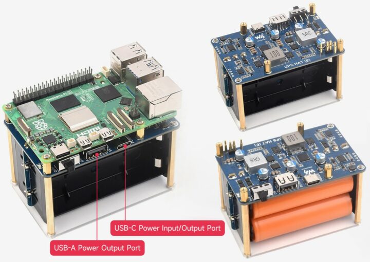
The Waveshare UPS HAT (E) is a UPS expansion board for Raspberry Pi 5/4B/3B+ that supports four 21700 Lithium batteries and includes a battery fuel gauge IC for monitoring voltage, current, and capacity. The USB Type-C port is compliant with the PD 3.0 standard and allows for 40W fast bi-directional charging, and a high-power buck chip provides a 5V/6A output. Additionally, it supports I2C for real-time status updates.
Previously, we wrote about the wider SupTronics Raspberry Pi 5 UPS HAT, which
The Waveshare UPS HAT (E) is a UPS expansion board for Raspberry Pi 5/4B/3B+ that supports four 21700 Lithium batteries and includes a battery fuel gauge IC for monitoring voltage, current, and capacity. The USB Type-C port is compliant with the PD 3.0 standard and allows for 40W fast bi-directional charging, and a high-power buck chip provides a 5V/6A output. Additionally, it supports I2C for real-time status updates.
Previously, we wrote about the wider SupTronics Raspberry Pi 5 UPS HAT, which supports four 18650 batteries and delivers up to 5V with a higher current output of 5A. This HAT has no Type-C support and uses a DC jack and XH2.54 connector for 6V-18V input. Feel free to check it out if you’re interested in this product.
MCU Management – Detects power connection and manages Raspberry Pi booting
Automatic Switch Over – Switches to battery power if the external supply fails
LED Indicators
Indicators for battery connection and charging status
Warning alerts if the battery is incorrectly connected.
Power Supply
5V/5A USB Type-C power supply recommended
2x pogo pin to power the Raspberry Pi
Charging
USB Type-C Port – Supports INA219 IC for bi-directional fast charging up to 40W, compatible with PD 3.0
Simultaneous Operation – Can charge batteries and provide power output at the same time
Dimensions – 88 x 56mm
The company shares a list of mostly generic safety instructions and warnings. Some of the most important points are
Li-ion and Li-po batteries can be unstable; improper use can cause fire, injury, or damage.
Do not reverse polarities when charging or discharging.
Use only quality chargers to recharge batteries.
Do not mix old and new batteries or use different brands of batteries together.
Ensure battery specifications match the expansion board.
Replace batteries after their cycle life ends or after two years of use.
To use the Waveshare UPS HAT (E) with Raspberry Pi, some Python commands enable the I2C interface, INA219 battery level detection, and battery level logo on the display. You can also set the required current to boot and adjust the booting time based on the power applied.
For more information about hardware and software, you can visit the product’s wiki page although the company does not provide specific hardware details such as IC part numbers or schematics.
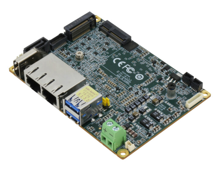
The AAEON PICO-MTU4 Pico-ITX SBC may be the world’s smallest platform based on 14th Gen Intel Core Ultra 5/7 SoCs part of the Meteor Lake-U family and follows the company’s UP Xtreme i14 SBC introduced a couple of months ago with the same processors, although the new model is limited to 15W parts due to its small size (100x72mm).
The Core Ultra 5/7 Pico-ITX SBC comes with up to 64GB DDR5 memory, supports NVMe and SATA storage, offers 2.5GbE and GbE networking, M.2 Key-M and Key-E sockets for sto
The AAEON PICO-MTU4 Pico-ITX SBC may be the world’s smallest platform based on 14th Gen Intel Core Ultra 5/7 SoCs part of the Meteor Lake-U family and follows the company’s UP Xtreme i14 SBC introduced a couple of months ago with the same processors, although the new model is limited to 15W parts due to its small size (100x72mm).
The Core Ultra 5/7 Pico-ITX SBC comes with up to 64GB DDR5 memory, supports NVMe and SATA storage, offers 2.5GbE and GbE networking, M.2 Key-M and Key-E sockets for storage or/and wireless expansion, dual display support through HDMI and eDP, a few USB interfaces, and two RS232/RS422/RS485 interfaces.
All model features Intel Arc graphics with AV1 encode/decode, H.265 (HEVC) 8-bit codec, DX 12.1, OpenGL 4.6, oneAPI
System Memory – Up to 64GB onboard LPDDR5 (single-channel)
Storage
M.2 2280 M-Key socket for SSD (NVMe PCIe Gen4 x4 or SATA as hardware option)
SATA III 6Gb/s port and 5V SATA power connector
Video Output
HDMI 1.4 port up to 4Kp30 (CNXSoft: odd that HDMI 2.1 or 2.0 is not supported, but HDMI 1.4 is confirmed in both the datasheet and product page [Update: see comments section as to why].
eDP 1.4 connector
Dual independent display support
Networking
2.5GbE port via Intel I226 controller
Gigabit Ethernet RJ45 port via Intel I219 controller
Optional WiFi 6 and Bluetooth 5.x via M.2 E-Key socket
AAEON officially supports Windows 10 64-bit and Ubuntu 22.04.2 with Linux 5.19, but I don’t see why Windows 11 and Ubuntu 24.04 could not be supported unless some drivers are missing. Talking about drivers, you’ll find those along with the BIOS, datasheet, and user manual on the product page.
AAEON says the board mainly targets the advanced industrial robotics market with SCADA, MES, and system monitoring devices singled out as particularly suitable use cases. The PICO-MTU4 is not yet listed on the company’s eStore and pricing has yet to be released. You can request a quote and/or more information on the product page.
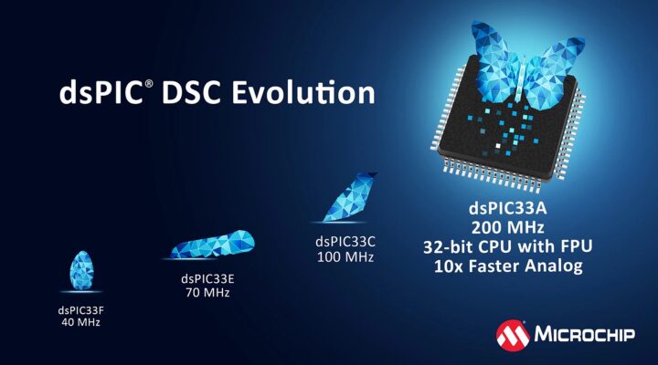
Top digital signal controller (DSC) vendor, Microchip Technology Inc., has launched the dsPIC33A series as the newest addition to its portfolio of high-performance DSCs. These digital signal controllers combine the capabilities of a digital signal processor (DSP) with the extensive peripherals of a microcontroller (MCU).
Fastest dsPIC yet
The dsPIC33A series is built around a 32-bit architecture and operates at 200MHz – currently the highest clock speed for a dsPIC. The core includes a double-pr
Top digital signal controller (DSC) vendor, Microchip Technology Inc., has launched the dsPIC33A series as the newest addition to its portfolio of high-performance DSCs. These digital signal controllers combine the capabilities of a digital signal processor (DSP) with the extensive peripherals of a microcontroller (MCU).
Fastest dsPIC yet
The dsPIC33A series is built around a 32-bit architecture and operates at 200MHz – currently the highest clock speed for a dsPIC. The core includes a double-precision floating-point unit (DP FPU) and a DSP instruction set for numerically intensive operations in closed-loop control algorithms. The dsPIC33A architecture offers high-performance, high-precision real-time control and signal processing in various applications.
dsPIC33A architecture
The family of DSCs launching the dsPIC33A series, dsPIC33AK128MC1xx, features up to 128KB of flash memory, and an extensive set of built-in peripherals. It comes in different packages, including SSOP, VQFN, and TQFP, with pin counts ranging from 28 to 64 and sizes starting as small as 4 x 4mm. Later dsPIC33A families are to come with more memory, peripherals, and pins.
The dsPIC33A family is bound for applications that require efficient motor control in fans, pumps, and compressors. They are also well-suited for managing digital power conversion in AI servers and electric vehicles and can facilitate sensor interfacing for industrial and automotive applications. It can used in products similar to the SaraKIT carrier board which incorporates a dsPIC33 chip and a Raspberry Pi CM4.
Processing – 32-bit CPU @ 200MHz clock speed; dual 72-bit accumulators supporting 32-bit and 16-bit fixed-point DSP operations; single and double-precision floating-point Unit (FPU) co-processor
Memory – 128KB code flash memory, 16KB RAM
Analog Peripherals – 4x high-speed PWM generators with 8x channels; 2x 12-bit ADC with 40 mega samples per second (Msps) conversion rate; 3x 5ns analog comparators and 3x 100MHz op-amp; 4x 10 μA constant sources and 4x programmable sources
Security – Secure boot, Secure debug, Immutable Root of Trust (IRT), Firmware IP Protection, Flash Write Protection
Qualification – AEC-Q100 REV H; Grade 1: -40°C to +125°C
Hardware and software support for the dsPIC33A family includes the MPLAB XC-DSC compiler, the MPLAB Code Configurator, and a development board — the EV74H48A Curiosity Platform. The development board includes mikroBUS and Xplained Pro interfaces for connecting extension kits, sensors, and Click boards. The devices also come as two separate dual in-line modules (DIM) compatible with motor control, digital power conversion, and general-purpose embedded applications.
dsPIC33A Curiosity Platform Development Board
Devices in the dsPIC33A family are currently available for less than $1 in high volumes. The EV74H48A Curiosity Platform development board is priced at $98, with possible discounts for bulk orders. Microchip Direct also lists two dsPIC33A DIM modules for $18 each, a PIM module (Processor Plug-In) for $49, and an optional $5,000 package for functional safety, but no dsPIC33A chips. Interested buyers should contact a Microchip sales representative, or authorized distributor for the chip themselves. More information about the new dsPIC33A series can be found on the product page and press release.
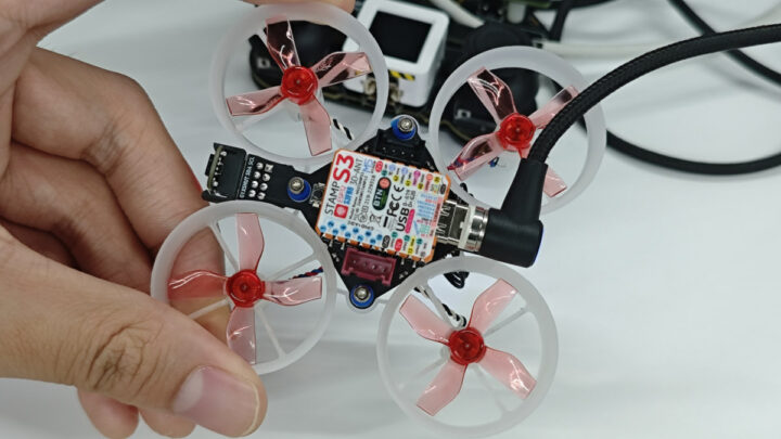
M5Stack M5Stamp Fly is a tiny ESP32-S3 WiFi drone based on the company’s M5Stamp S3 WiFi 4 and BLE IoT module, equipped with four motors and several sensors. and controllable the M5Atom WiFi joystick controller also based on ESP32-S3 WiSoC.
We have recently seen some tiny ESP32 or ESP8266 WiFi drones with a low-cost ESP32 DIY drone and the PiWings 2.0 drone, but the M5Stamp Fly is more advanced with a total of six sensors including a barometer, two time-of-flight distance sensors, a 6-axis IMU,
M5Stack M5Stamp Fly is a tiny ESP32-S3 WiFi drone based on the company’s M5Stamp S3 WiFi 4 and BLE IoT module, equipped with four motors and several sensors. and controllable the M5Atom WiFi joystick controller also based on ESP32-S3 WiSoC.
We have recently seen some tiny ESP32 or ESP8266 WiFi drones with a low-cost ESP32 DIY drone and the PiWings 2.0 drone, but the M5Stamp Fly is more advanced with a total of six sensors including a barometer, two time-of-flight distance sensors, a 6-axis IMU, a 3-axis magnetometer, and an optical flow detection sensors, plus two Grove connector for additional sensors or modules.
WiSoC – Espressif Systems ESP32-S3FN8 dual-core 32-bit Xtensa LX7 microcontroller with AI vector instructions up to 240MHz, RISC-V ULP co-processor, 512KB SRAM, 2.4GHz WiFi 4 (802.11b/g/n), Bluetooth 5.0 BLE + Mesh, 8MB flash
Connectivity
2.4 GHz WiFi 4, 20 MHz and 40 MHz bandwidth, IEEE 802.11 b/g/n protocol, up to 150 Mbps
Bluetooth 5, Bluetooth Mesh, with supports for 125 Kbps, 500 Kbps, 1 Mbps, 2 Mbps bitrate, long-range support
2.4GHz 3D antenna
USB – 1x USB Type-C port for power and programming
Expansion – 2.54mm and 1.27mm pitch headers and castellated holes with GPIOs, SPI, PWM, etc…
2x VL53L3 ToF distance sensors (up to 3-meter range) for altitude hold and obstacle avoidance
6-axis BMI270 attitude/IMU sensor
3-axis BMM150 magnetometer for direction detection
Optical flow detection for hovering and displacement detection (PMW3901MB-TXQT)
Expansion – 2x 4-pin Grove connectors (1x I2C, 1x UART)
Misc – Passive buzzer, RGB LED, Reset button
Power Management
300mAh high-voltage battery
5V charging via USB-C port
INA3221AIRGVR current and voltage detection chip
Dimensions – 81.5 x 81.5 x 31mm
Temperature Range – 0 to 40°C
Weight – 36.8grams
As noted earlier, the M5Stamp Fly can be controlled using the M5Atom Joystick (K137) based on the M5Stack AtomS3 ESP32-S3 IoT controller and relying on the ESPNOW low-power proprietary protocol for point-to-point communication between the drone and the joystick without the need for a router. M5Stack explains users can choose between automatic and manual modes to enable/disable functions like precise hovering and flips.
The firmware C/C++ source code is available for both the drone and the joystick and you’ll find documentation to flash both and instructions to use the drone in the documentation website. Note there does not seem to be a way to control the drone with a smartphone at this time. The company says the M5Stamp Fly drone is suitable for education, research, and various drone development projects.
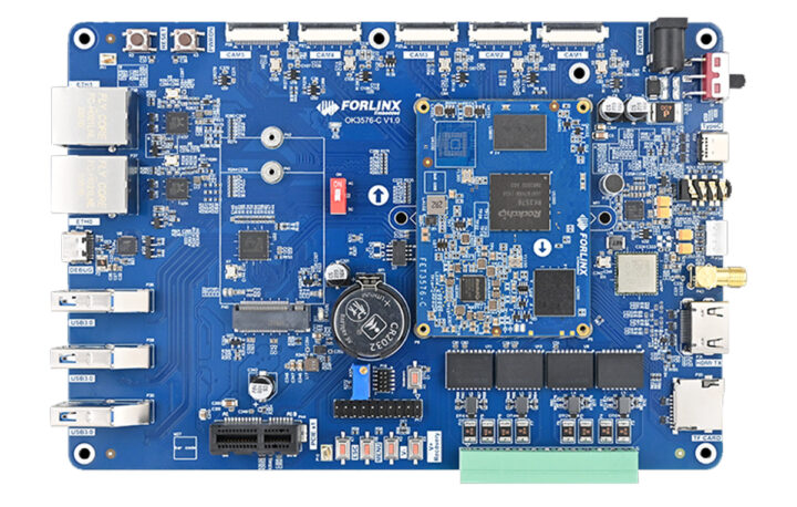
Boardcon CM3576 is a system-on-module (SoM) Rockchip RK3576 with castellated holes that also powers the company’s EM3576 development board with 12 analog camera inputs among a range of other interfaces.
We covered a few Rockchip RK3576 platforms in recent weeks including the Firefly ROC-RK3576-PC and Banana Pi BPI-M5 SBCs, and another system-on-module with the Forlinx FET3576-C with four 100-pin board-to-board connectors. The Boardcon CM3576 offers another option as a solderable SoM with castell
Boardcon CM3576 is a system-on-module (SoM) Rockchip RK3576 with castellated holes that also powers the company’s EM3576 development board with 12 analog camera inputs among a range of other interfaces.
We covered a few Rockchip RK3576 platforms in recent weeks including the Firefly ROC-RK3576-PC and Banana Pi BPI-M5 SBCs, and another system-on-module with the Forlinx FET3576-C with four 100-pin board-to-board connectors. The Boardcon CM3576 offers another option as a solderable SoM with castellated edges.
4x Cortex-A72 cores at 2.3GHz, 4x Cortex-A53 cores at 2.2GHz
Arm Cortex-M0 MCU at 400MHz
GPU – ARM Mali-G52 MC3 GPU with support for OpenGL ES 1.1, 2.0, and 3.2, OpenCL up to 2.0, and Vulkan 1.1
NPU – 6 TOPS (INT8) AI accelerator with support for INT4/INT8/INT16/BF16/TF32 mixed operations.
VPU
Video Decoder – H.264, H.265, VP9, AV1, and AVS2 up to 8Kp30 or 4Kp120
Video Encoder – H.264 and H.265 up to 4Kp60, (M)JPEG encoder/decoder up to 4Kp60
System Memory – 2GB, 4GB, 8GB, or 16GB LPDDR4 RAM
Storage – 32GB, 64GB, or 128GB eMMC flash
Networking – RealTek RTL8211F Gigabit Ethernet transceiver (Note: the development board specifications list the pin-compatible Motorcomm YT8531 instead)
218x castellated holes with
Storage – SATA, 2x SDMMC
Display I/F – HDMI, MIPI DSI, RGB/EBC, DP via USB 3.2
Block diagram for CM3576 module and EM3576 development board
Boardcon provides support for Android 14 with Linux 6.1.57 through a BSP providing all necessary drivers and a development environment (virtual machine image?) based on Ubuntu 22.04.
EM3576 Rockchip RK3576 development board
Evaluation and early software development can be performed on the EM3576 development board equipped with the CM3576 module described above and exposing a range of interfaces including twelve analog camera inputs. The company, or its customers, appear to be a big fan of such camera inputs, as they also introduced the Boardcon EM3568-AV CAM SBC with a Rockchip RK3568 SoC and four analog camera inputs.
Boardcon EM3576 specifications:
SoM – Board CM3576 SoM described above with 2GB RAM and 32GB eMMC flash by default
Storage – MicroSD card slot, M.2 PCIe socket for 2230/2242/2280 NVMe SSD, SATA port multiplexed with USB 2.0
Display
HDMI 2.1 up to 4Kp120
4-lane MIPI DSI connector up to 2Kp60
RGB connector (multiplexed with SPI & 2x UART)
Audio
2x 3.5mm audio jacks for Line in/Line out
2-pin MIC connector
Camera – 12x analog HD camera BNC connectors
Networking
Gigabit Ethernet RJ45 via Motorcomm YT8531 controller
Dual-band WiFi 5 and Bluetooth 5.0 2×2 MIMO module with three IPEX antenna connectors
10-pin connector for NFC
USB – 1x USB 3.2 Type-C port with DisplayPort Alt mode, 1x USB 2.0 Host port (multiplexed with SATA)
Serial
2x 4-pin UART connectors
3-pin debug connector
RS485 via 3-pole terminal block
CAN Bus via 2-pole terminal block
Misc
Reset, Recovery, and Power buttons
RTC with battery connector
SPI connector
GPIO connector with 1x I2C, 3x GPIO
Power Supply – 12V/3A via DC jack or 2-pin connector
Dimensions – 170 x 120 mm
Boardcon says the CM3576 system-on-module and EM3576 development board are suitable for industrial HMI, motion control and robotics, multi-camera monitoring, driver and occupant monitoring systems (DMS, OMS), automatic vehicle identification, home security and surveillance, etc…
The company does not provide public pricing information and asks interested parties to contact them for pricing. Additional information may be found on the product page.
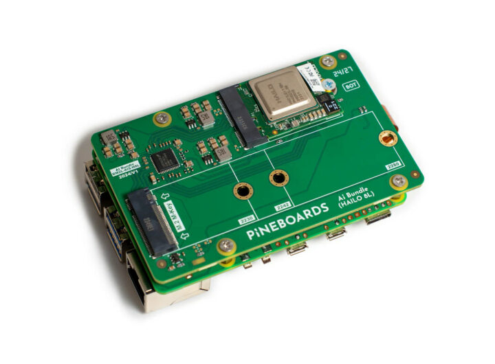
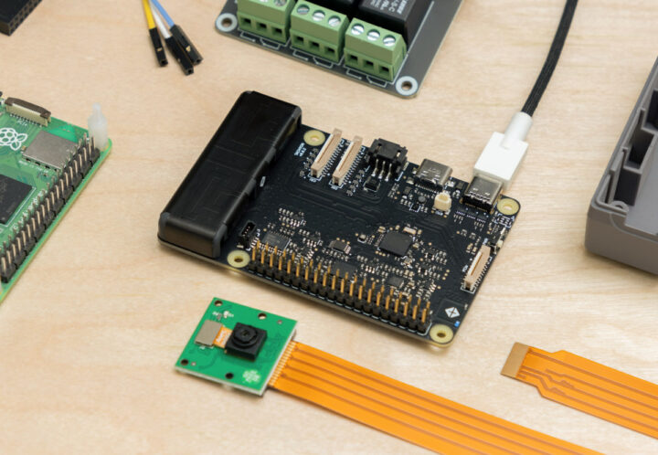
Pineboards has launched yet another Raspberry Pi 5 HAT+ expansion board with the Ai Bundle (Hailo 8L) which includes a 13 TOPS Hailo 8L AI accelerator and an M.2 PCIe socket for an NVMe SSD.
The latest Raspberry Pi 5 HAT+ from Pineboards combines the capabilities of the official Raspberry Pi AI Kit and Raspberry Pi M.2 HAT+ into a single board, while supporting longer M.2 2280 NVMe SSD drives, besides shorted 2230 and 2242-sized SSDs.
Pineboards Ai Bundle (Hailo 8L) specifications:
Compatible
Pineboards has launched yet another Raspberry Pi 5 HAT+ expansion board with the Ai Bundle (Hailo 8L) which includes a 13 TOPS Hailo 8L AI accelerator and an M.2 PCIe socket for an NVMe SSD.
The latest Raspberry Pi 5 HAT+ from Pineboards combines the capabilities of the official Raspberry Pi AI Kit and Raspberry Pi M.2 HAT+ into a single board, while supporting longer M.2 2280 NVMe SSD drives, besides shorted 2230 and 2242-sized SSDs.
Pineboards Ai Bundle (Hailo 8L) specifications:
Compatible SBC – Raspberry Pi 5
Storage – M.2 2230/2242/2280 M-Key socket for NVMe SSD
AI accelerator – M.2 2230 A/E-Key socket fitted with Hailo 8L AI Accelerator (and thermal pad)
Accessories – FPC cable, metal screws and spacers (no low-quality plastic screws…)
Dimensions – About 90 x 55 mm
Before you could reproduce this setup with the HatBRICK! Commander, but you would have ended up with three expansion boards and a mess on your desk, while the Ai Bundle (Hailo 8L) fits nicely under the Raspberry Pi 5.
Software-wise nothing has changed and you can keep using the same software such as rpicam-apps for the Hailo 8L module, and boot Raspberry Pi OS from fast NVMe storage without requiring a microSD card.
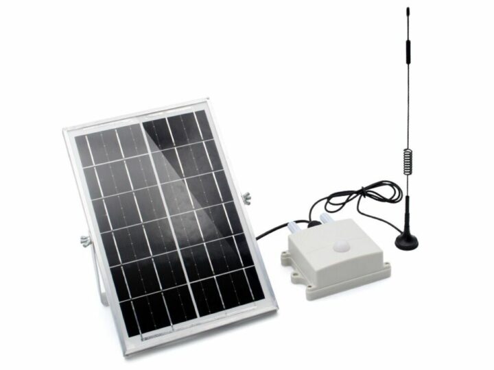
The NBIOT/LTE-M Air Monitor is a solar-powered device that utilizes a combination of ESP32-S3 and SIM7080G modules for remote environmental monitoring. It monitors and transmits environmental parameters such as temperature, humidity, CO2, TVOC, and light intensity using low-power wide-area network (LPWAN) technology ensuring efficient power consumption, durability, and reliable data transmission.
Previously we have written about similar environment monitor devices like the Airlytix ES1, Sonoff
The NBIOT/LTE-M Air Monitor is a solar-powered device that utilizes a combination of ESP32-S3 and SIM7080G modules for remote environmental monitoring. It monitors and transmits environmental parameters such as temperature, humidity, CO2, TVOC, and light intensity using low-power wide-area network (LPWAN) technology ensuring efficient power consumption, durability, and reliable data transmission.
MPPT – CN3791 for solar maximum power tracking charging management
Temperature Range – -40°C to +85°C
As I noticed, there is only a programming pin available. To program, plug the USB2UART CH340K module into the “P1” header (‘The “P1” connector is a 6-pin programmable header for the ESP32, including pins for RST, BOOT, TXD, RXD, GND, and VOUT.). This module provides USB to serial conversion and includes the necessary circuits for ESP8266/ESP32 programming.
Makerfabs highlights Arduino support with the ESP32-S3 wireless module and also explains how to send an email from the air monitor and integrate it with ThingSpeak IoT cloud. You will find more information about hardware, programming, drivers, and firmware on the wiki and GitHub pages.
Example charts in Thingspeak with data from the NBIOT/LTE-M Air Monitor
The NBIOT/LTE-M Air Monitor is available on its official Makerfabs store for $68.80 plus shipping. The additional ESP32 Programmer board (USB2UART CH340K) is also available in the same store at $3.90.
HACS, microWakeWord, and Music Assistant projects have joined the Open Home Foundation launched a few months ago to manage open-source projects related to Home Assistant and Smart Home applications in general separating them from Nabu Casa’s commercial activities.
Note the HACS, microWakeWord, and Music Assistant projects will not operate directly under the Open Home Foundation’s umbrella, but they are external projects that the foundation collaborates on since it believes those are projects wor
HACS, microWakeWord, and Music Assistant projects have joined the Open Home Foundation launched a few months ago to manage open-source projects related to Home Assistant and Smart Home applications in general separating them from Nabu Casa’s commercial activities.
Note the HACS, microWakeWord, and Music Assistant projects will not operate directly under the Open Home Foundation’s umbrella, but they are external projects that the foundation collaborates on since it believes those are projects worth investing in to further develop the Smart Home ecosystem. Let’s have a quick look at the three projects.
Home Assistant Community Store (HACS) is the most used custom integration for Home Assistant and allows users to easily install custom integrations, cards, and themes.
Music Assistant gives users control over their media players and audio files handling both local music collection and music streaming services so that users can play any tune anywhere in their house without restrictions.
microWakeWord is an on-device wake word engine for microcontrollers such as ESP32 that can power onboard wake word on local and open-source voice satellites. Models are suitable for using TensorFlow Lite for Microcontrollers and the project is also integrated into ESPHome. One hardware device suitable for the project is the tiny M5Stack Atom Echo speaker.
Home Assistant HACS integration
The Open Home Foundation announced the collaboration with these new projects in their newsletter where they also highlighted the risk of going with commercial-only solutions as LG acquired a majority stake in Athom, the makers of Homey, and covered the recent release of Home Assistant 2024.07 which enables users to make use of timers on voice assistants, adds scripting to LLM capabilities, updates ESPHome over-the-air (OTA), etc…
Thanks to Hedda for the tip.
[Update Aug 2: the article has been edited to reflect none of the three projects are directly managed by the Open Home Foundation.]
Initially teased at the Orange Pi Developer Conference earlier this year, the Orange Pi 5 Max SBC powered by a Rockchip RK3588 SoC is now available on Amazon and Aliexpress for $95 and up with 8GB or 16GB LPDDR5, and support for eMMC flash modules or soldered on eMMC flash. A 4GB RAM version is also planned for $75.
The Orange Pi 5 Max is basically a cost-down version of the Orange Pi 5 Plus with fewer interfaces (e.g. 1x 2.5GbE vs 2x 2.5GbE, no HDMI input, etc..), higher bandwidth LPDDR5 memory
Initially teased at the Orange Pi Developer Conference earlier this year, the Orange Pi 5 Max SBC powered by a Rockchip RK3588 SoC is now available on Amazon and Aliexpress for $95 and up with 8GB or 16GB LPDDR5, and support for eMMC flash modules or soldered on eMMC flash. A 4GB RAM version is also planned for $75.
The Orange Pi 5 Max is basically a cost-down version of the Orange Pi 5 Plus with fewer interfaces (e.g. 1x 2.5GbE vs 2x 2.5GbE, no HDMI input, etc..), higher bandwidth LPDDR5 memory, onboard WiFi 6E and Bluetooth 5.3, and a smaller form factor between Pico-ITX and credit card size.
3.5mm audio jack with headphone and microphone support
Onboard MIC
Support for HDMI 2.1 eARC
Networking
2.5GbE RJ45 port via RTL8125BG controller
Onboard WiFi 6E and Bluetooth 5.3 module (AP6611) using SDIO 3.0 for WiFi, UART and PCM for Bluetooth; IPEX antenna connector
USB – 2x USB 3.0 ports, 2x USB 2.0 ports
Expansion
40-pin header with GPIO, UART, I2C, SPI, CAN, PWM, and others
M.2 Key-M socket (PCIe 3.0 x4) for a 2280 NVMe SSDs, or other PCIe 2280 modules (e.g. AI accelerators)
Debugging – UART on 40-pin header
Misc
Power and MaskROM buttons
Power LED
2-pin 5V fan connector
2-pin connector for RTC backup battery
Power Supply
5V/5A via USB Type-C port
RK806-1 PMU
Dimensions – 96 x 57 mm
Weight – 62 grams
Orange Pi provides support for Orange Pi OS (Android, Arch, or OpenHarmony), Ubuntu 20.04/22.04, Debian 11/12, OpenWrt (I’m not sure why), and Android 13. You’ll find all those images and source code on the Download page.
Official pricing for the board is:
$75 with 4GB RAM
$95 with 8GB RAM
$125 with 16GB RAM
You can get those prices on AliExpress where you’ll also find accessories, or pay a little more on Amazon. Versions with soldered-on eMMC flash are not available yet but might be made upon request (possibly with MOQ). Additional information may be found on the product page.
Particle Tachyon is a credit card-sized SBC for AIoT projects powered by a Qualcomm QCM6490 octa-core Cortex-A78/A55 SoC with 12 TOPS of AI performance, 4GB RAM, 64GB UFS storage, and support for 5G cellular and WiFi 6 connectivity.
The Tachyon integrates MIPI DSI and CSI display/camera interfaces, two USB-C ports including one with DisplayPort Alt mode, and also leverages some Raspberry Pi 5’s hardware features with a 40-pin GPIO header for HAT expansion boards and the 20-pin PCIe FFC for PCIe
Particle Tachyon is a credit card-sized SBC for AIoT projects powered by a Qualcomm QCM6490 octa-core Cortex-A78/A55 SoC with 12 TOPS of AI performance, 4GB RAM, 64GB UFS storage, and support for 5G cellular and WiFi 6 connectivity.
The Tachyon integrates MIPI DSI and CSI display/camera interfaces, two USB-C ports including one with DisplayPort Alt mode, and also leverages some Raspberry Pi 5’s hardware features with a 40-pin GPIO header for HAT expansion boards and the 20-pin PCIe FFC for PCIe add-ons.
CPU – Octa-core Kryo 670 with 1x Gold Plus core (Cortex-A78) @ 2.7 GHz, 3x Gold cores (Cortex-A78) @ 2.4 GHz, 4x Silver cores (Cortex-A55) @ up to 1.9 GHz
GPU – Adreno 643L GPU @ 812 MHz with support for Open GL ES 3.2, Open CL 2.0, Vulkan 1.x, DX FL 12
DSP – Hexagon DSP with dual HVX and 4K HMX
VPU – Adreno 633 VPU up to 4K60 decode for H.264/H.265/VP9, Up to 4K30 encode for H.264/H.265; Support for HDR10 and HDR10+ playback
AI – 6th gen Qualcomm AI Engine that combines Compute Hexagon DSP with dual Hexagon Vector, eXtensions (HVX), Hexagon Co-processor (Hexagon CP) 2.0 and Hexagon Tensor accelerator for up to 12 TOPS of AI performance
System Memory – 4GB RAM
Storage – 64GB UFS storage
Display Interfaces
1x DisplayPort via USB-C
4-lane MIPI DSI connector
Camera Interface – 2x 4-lane MIPI CSI connector supporting 20 pre-integrated camera sensors
Wireless
5G Sub-6GHz cellular connectivity with on-device antennas
WiFi 6E (802.11ax) with on-device antennas
GNSS – GPS, GLONASS, NavIC, BeiDou, Galileo, QZSS, and SBAS
USB – 2x USB 3.1 Type-C ports with USB PD, one with DisplayPort Alt mode
40-pin GPIO header compatible with Raspberry Pi HAT expansion boards
Power Supply
USB PD via USB-C port
Support for Lithium Ion battery; integrated battery charging circuit
Dimensions – Business card dimensions (about 86x 55mm)
Tachyon with Raspberry Pi HAT
The Tachyon SBC runs Ubuntu 24.04 Desktop operating system by default, but a headless version of Ubuntu 24.04 is also available, and so is the Yocto Project for advanced users who need to customize the OS. As for their other products, Particle provides a complete edge-to-cloud infrastructure to get started quickly and easily for the board. It includes device management, OTA software updates, connectivity management, and data automation.
First unveiled in 2021, the Qualcomm QCS6490/QSM6490 5G cellular and WiFi 6E octa-core Arm Cortex-A78/A55 SoC with 12 TOPS of AI performance was launched in the Qualcomm RB3 Gen 2 Platform for IoT and Robotics applications earlier this year and also happens to have been selected for the Fairphone 5 smartphone for its long term support. The Tachyon may eventually benefit from those, as the QCS9460/QCM9460 SoC runs mainline Linux, and supports Android 13, and Windows 11.
Particle Cloud Dashboard
Particle has been making IoT products and tools for over ten years starting with the Spark Core WiFi module in 2013, followed by the Electron cellular module in 2015, and recent products include the Particle’s M-series multi-radio devices with WiFi, cellular, NTN satellite, and LoRaWAN connectivity, as well as the Photon 2 Realtek RTL8721DM dual-band WiFi and BLE IoT board. The Tachyon is by far the most powerful IoT platform launched by the company.
Particle has just launched the Tachyon SBC on Kickstarter with a $10,000 funding goal that has already been easily surpassed in less than a day. Rewards start at $149 for the “Super early bird” perk, and latecomers would have to pay $199 or $219. Shipping adds $12 to the US and $20 to the rest of the world, and deliveries are scheduled to start in January or February 2025.
No need to check the calendar, it’s not the first of April, and Tuya Ivy is indeed a smart WiFi-connected flower pot with a display that will report your plant’s thirst for water, need for more light, and even loneliness…
Developed by PlantsIO, the Ivy smart flower pot is powered by an ESP32 wireless microcontroller connected to seven sensors including lighting and moisture sensors, and a display to show various faces. There’s also a USB-C port for power, a microSD card slot for data storage, so
No need to check the calendar, it’s not the first of April, and Tuya Ivy is indeed a smart WiFi-connected flower pot with a display that will report your plant’s thirst for water, need for more light, and even loneliness…
Developed by PlantsIO, the Ivy smart flower pot is powered by an ESP32 wireless microcontroller connected to seven sensors including lighting and moisture sensors, and a display to show various faces. There’s also a USB-C port for power, a microSD card slot for data storage, some buttons, and a touch bar for user interaction.
Tuya Ivy specifications:
Wireless module – ESP32-WROVER-E
SoC – ESP32 dual-core LX6 processor running at 240 MHz with 520KiB internal RAM
Memory – 64 Mbit PSRAM (ESP PSRAM64H)
Storage – 64Mbit SPI flash (XMC 25QH64CH10)
Wireless – 2.4 GHz WiFi and Bluetooth 5.x (Only WiFi appears to be use)
Storage – microSD card
Display – Tri-color display (black, white, and red)
Sensors – 7x sensors including light intensity sensor, soil moisture sensor, temperature and humidity sensor
Misc – Front button, back button, touch bar
Power Supply
5V DC via USB-C port
2,000 mAh Lithium battery
Dimensions – 11.4 x 10 x 9.6 cm
Temperature Range – 5 to 35°C (designed for indoor use only)
The Tuya Ivy ships with surface pebbles, a USB Type-C cable, an inner pot, a measuring cup, and a user manual. You just need to bring your own plant. Like other Smart Home devices from the company, it relies on the Tuya Smart Life mobile available for Android or iOS for setup and receiving notifications. The company mentions 49 expressions, so it’s not only about lighting and moisture, and five gestures are supported so you can caress the pot or pet your plant like you would with a dog and it will make it very happy !
Since it’s a consumer device, Tuya did not provide that many technical details, but X user atc1441 noticed some photos of the Smart Planter’s board on the FCC website, which I used to derive parts of the specifications above.
The Tuya Ivy smart flower pot was introduced last year, so we have some user feedback, and people who purchased it on AliExpress (now about $50) seem to be happy about it.
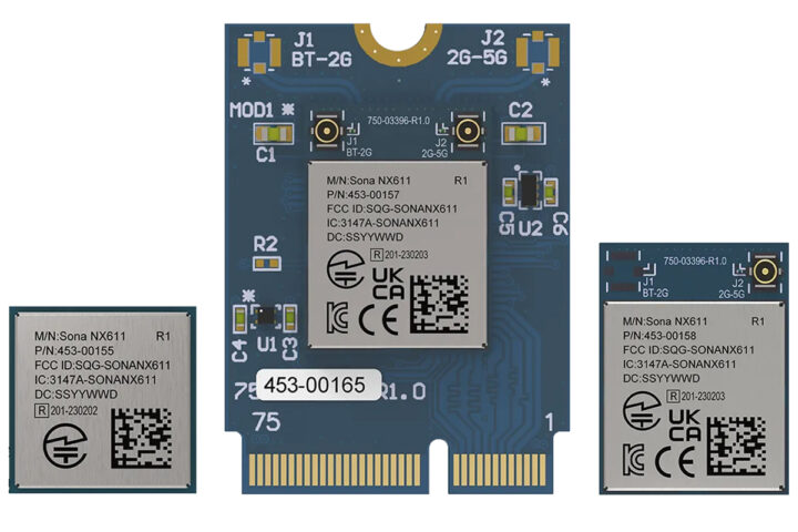
Ezurio, formerly Laird Connectivity, has announced the Sona NX611, a new Wi-Fi 6 module designed for industrial IoT applications. The module uses the NXP IW611 chipset and supports Wi-Fi 6 (802.11ax) and Bluetooth 5.4. It operates in the 2.4 GHz and 5 GHz bands, achieving data rates up to 600 Mbps, and can withstand industrial temperatures from -40°C to +85°C.
The Sona NX611 comes in several form factors, including SiP (System-in-Package), M.2 1216 SMT, and M.2 2230 E-Key pluggable options. It i
Ezurio, formerly Laird Connectivity, has announced the Sona NX611, a new Wi-Fi 6 module designed for industrial IoT applications. The module uses the NXP IW611 chipset and supports Wi-Fi 6 (802.11ax) and Bluetooth 5.4. It operates in the 2.4 GHz and 5 GHz bands, achieving data rates up to 600 Mbps, and can withstand industrial temperatures from -40°C to +85°C.
The Sona NX611 comes in several form factors, including SiP (System-in-Package), M.2 1216 SMT, and M.2 2230 E-Key pluggable options. It is compatible with NXP processors and supports Ezurio’s Linux connectivity stack software and Android OS. The module is under development and is expected to be in mass production by September 2024. It will have global certifications like FCC, ISED, UKCA, CE, and Bluetooth SIG.
Ezurio Sona NX611 industrial Wi-Fi 6 module specification
Main Chip – Sona NX611 based on NXP IW611 or IW612
Wi-Fi
Wi-Fi 6 (802.11 a/b/g/n/ac/ax)
Dual-band 2.4 GHz & 5 GHz
2.4 GHz: Up to 287 Mbps, 1024-QAM, 1×1 MCS7)
5 GHz: Up to 600 Mbps, 1024-QAM, 1×1 (MCS11)
Supports OFDMA, TWT, BSS Coloring
802.11d/e/h/i/j/k/mc/r/v/w
Bluetooth
v5.4 (BDR + EDR + BLE)
LE 2 Mbps PHY
LE Coded (Long range PHY)
Adaptive Frequency hopping (AFH)
Secure simple pairing (SSP)
UART baud rates up to 4 Mbps
7 x BT links/16 x BLE links
Secure connection (AES128 & ECC256)
Antenna Options
On-board MHF4 connector(s)
Trace pin for external antennas
Integrated chip antenna
Combined Wi-Fi and BT antenna RF connections
Host Interface and Peripherals
SDIO 3.0 (Wi-Fi)
HS-UART (BT)
PCM (BT Audio)
Input Voltage Requirements
SIP-76-pin LGA package
3.3V nominal 3.3V Typ, 3.14V Min, 3.46V Max
1.8V nominal 1.8V Typ, 1.71V Min, 1.89V Max
1216-96-pin LGA
3.3V nominal 3.3V Typ, 3.14V Min, 3.46V Max
2230 Key E package
3.3V nominal 3.3V Typ, 3.14V Min, 3.46V Max
Dimensions (and antenna type)
11 x 11 mm (SIP) – RF Pin
16 x 12 mm (M.2 1216 SMT Module) – MHF4 and RF Pin
18 x 12 mm (M.2 1218 SMT Module) – Chip Antenna
30 x 22 mm (M.2 E-Key Module) – MHF4
Environmental
Operating Temp Range: -40°C to +85°C
Operating Humidity – Less than 85% RH (non-condensing)
Storage Temperature: -40° to +85°C (-40° to +185°F)
Storage Humidity – Less than 60% RH (non-condensing)
MSL (Moisture Sensitivity Level) – MSL4 (SIP), MSL1 (M2)
Regulatory approvals:
FCC/IC/CE/UKCA/RCM/MIC (Pending)
Bluetooth SIG Approval (Pending)
Ezurio provides a “Premium WiFi Advantage” program where experts handle everything from hardware design and testing to software integration and global certifications. They offer pre-certified Wi-Fi modules and antennas, ensuring your product meets international standards. Their Backports package, a full Linux Wi-Fi stack with drivers, network libraries, supplicant, and net-manager, is fully documented and supports Buildroot, Yocto, and Debian with regular updates planned.
Sona NX611 Development Kit
The company provides a total of four development boards for the Ezurio Sona NX611 modules, two with soldered modules and MHF4 and MHF antenna options, and the other two features M.2 E-Key modules with MHF4 and MHF antenna options. More information about the Ezurio Sona NX611 Wi-Fi module and its dev board can be found on the product page and the press release.
The Ezurio Sona NX611 Wi-Fi module and the devkit are available on all major platforms including DigiKey, Mouser, Avnet, and Future Electronics. The dev board for the module costs around $149, and the Wi-Fi modules cost between $16.16 to $17.32 depending on the module.
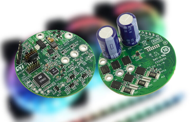
STMicroelectronics has recently revealed the reference design for “EVLDRIVE101-HPD” their homegrown BLDC motor driver board that can drive up to a 750W BLDC motor. This compact 50 mm (1.9-inch) circular PCB combines STDRIVE101 3-phase, triple half-bridge gate-driver IC with an STM32G0 microcontroller, which is responsible for driving three-phase brushless motors.
The driver board supports various motor-control strategies, including trapezoidal and field-oriented control (FOC), with both sensor’e
STMicroelectronics has recently revealed the reference design for “EVLDRIVE101-HPD” their homegrown BLDC motor driver board that can drive up to a 750W BLDC motor. This compact 50 mm (1.9-inch) circular PCB combines STDRIVE101 3-phase, triple half-bridge gate-driver IC with an STM32G0 microcontroller, which is responsible for driving three-phase brushless motors.
The driver board supports various motor-control strategies, including trapezoidal and field-oriented control (FOC), with both sensor’ed and sensorless rotor-position detection. Additionally, it has a wide operating voltage range of 5.5V to 75V and includes STL220N6F7 60V STripFET F7 MOSFETs, which have very low Rds(on) for high efficiency. Other features of the board include ultra-low power consumption in sleep mode, a single-wire debug interface, direct firmware update capability, and protection mechanisms such as under-voltage lockout, overtemperature protection, and cross-conduction prevention. All these features make this board suitable for applications like hairdryers, handheld vacuums, power tools, fans, drones, robots, and industrial equipment drives.
ST’s EVLDRIVE101-HPD BLDC motor driver specification
The EVLDRIVE101-HPD BLDC motor driver board includes the STDRIVE101 triple half-bridge gate driver, which is a single-chip, low-voltage gate driver for three-phase brushless motors. The chip has a wide input voltage range of 5.5 V to 75 V and includes an integrated low-drop linear regulator and bootstrap circuitry for gate driver supply, along with under-voltage lockout (UVLO) protection. It supports two input strategies, selectable via the DT/MODE pin, with cross-conduction prevention through interlocking or deadtime generation. Additional features include VDS monitoring for MOSFET protection, thermal shutdown, and a standby mode for reduced power consumption to 1 uA.
The company uses six STL220N6F7 MOSFETs for the gate driver IC which utilizes STripFET F7 technology with an enhanced trench gate structure that results in very low on-state resistance of 1.2mΩ, while also reducing internal capacitance and gate charge for faster and more efficient switching.
ST’s EVLDRIVE101-HPD board uses the STDRIVE101 and a TSV991ILT CMOS Op-Amp to achieve current sensing. The board also includes undervoltage lockout (UVLU), and back EMF (BEMF) current sensing and limiting. It also includes a connector for Hall-effect sensors and an encoder. More information about the board can be found on the ST’s product overview page and some more information is available on the press release. You can also check out the data brief and user manual for additional info which can be found on that same STs page.
The STMicro’s EVLDRIVE101-HPD BLDC motor driver board is priced at around $93.76 for a single unit and can be purchased from Mouser Electronic.
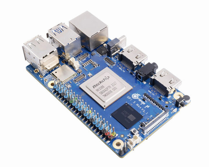
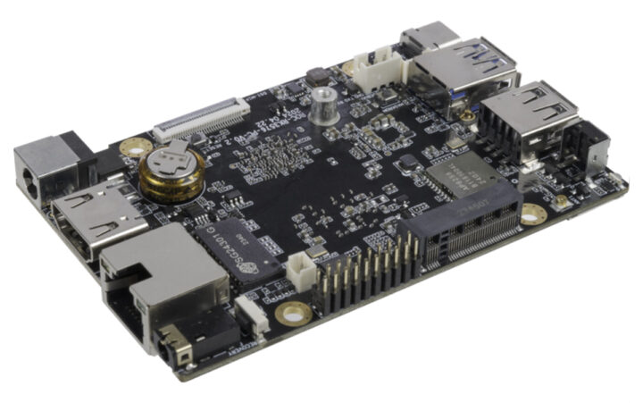
Firefly ROC-RK3576-PC is a low-power, low-profile SBC built around the Rockchip RK3576 octa-core Cortex-A72/A53 SoC which we also find in the Forlinx FET3576-C, the Banana Pi BPI-M5, and Mekotronics R57 Mini PC. In terms of power and performance, this SoC falls in between the Rockchip RK3588 and RK3399 SoCs and can be used for AIoT applications thanks to its 6 TOPS NPU.
Termed “mini computer” by Firefly this SBC supports up to 8GB LPDDR4/LPDDR4X memory and 256GB of eMMC storage. Additionally, it
Firefly ROC-RK3576-PC is a low-power, low-profile SBC built around the Rockchip RK3576 octa-core Cortex-A72/A53 SoC which we also find in the Forlinx FET3576-C, the Banana Pi BPI-M5, and Mekotronics R57 Mini PC. In terms of power and performance, this SoC falls in between the Rockchip RK3588 and RK3399 SoCs and can be used for AIoT applications thanks to its 6 TOPS NPU.
Termed “mini computer” by Firefly this SBC supports up to 8GB LPDDR4/LPDDR4X memory and 256GB of eMMC storage. Additionally, it offers Gigabit Ethernet, WiFi 5, and Bluetooth 5.0 for connectivity. An M.2 2242 PCIe/SATA socket and microSD card can be used for storage, and the board also offers HDMI and MIPI DSI display interfaces, two MIPI CSI camera interfaces, a few USB ports, and a 40-pin GPIO header.
4x Cortex-A72 cores at 2.2GHz, four Cortex-A53 cores at 1.8GHz
Arm Cortex-M0 MCU at 400MHz
GPU – ARM Mali-G52 MC3 GPU clocked at 1GHz with support for OpenGL ES 1.1, 2.0, and 3.2, OpenCL up to 2.0, and Vulkan 1.1 embedded 2D acceleration
NPU – 6 TOPS (INT8) AI accelerator with support for INT4/INT8/INT16/BF16/TF32 mixed operations.
VPU
Video Decoder: H.264, H.265, VP9, AV1, and AVS2 up to 8K at 30fps or 4K at 120fps.
Video Encoder: H.264 and H.265 up to 4K at 60fps, (M)JPEG encoder/decoder up to 4K at 60fps.
System Memory – 4GB or 8GB 32-bit LPDDR4/LPDDR4x
Storage
16GB to 256GB eMMC flash options
MicroSD card slot
M.2 (2242 PCIe NVMe/SATA SSD)
Footprint for UFS 2.0 storage
Video Output
HDMI 2.0 port up to 4Kp120
MIPI DSI connector up to 2Kp60
DisplayPort 1.4 via USB-C up to 4Kp120
Audio
3.5mm Audio jack (Support MIC recording and American Standard CTIA)
Line OUT
Camera I/F – 1x MIPI CSI DPHY(30Pin-0.5mm, 1*4 lanes/2*2 lanes)
Networking
Low-profile Gigabit Ethernet RJ45 port with Motorcomm YT8531
WiFi 5 and Bluetooth 5.2 via AMPAK AP6256
USB – 1x USB 3.0 port, 1x USB 2.0 port, 1x USB Type-C port
Expansion
40-pin GPIO header
M.2 for PCIe socket
Misc
External watchdog
4-pin fan connector
1x Debug port
I2C, SPI, USART
SARADC
Power
Supply voltage – DC 12V (5.5mm * 2.1mm, support 12V~24V wide voltage input)
Power Consumption – Normal: 1.2W(12V/100mA), Max: 6W(12V/500mA), Min: 0.096W(12V/8mA)
Dimensions – 93.00 x 60.15 x 12.49mm
Weight – 50 grams
Environment
Temperature Range: -20°C- 60°C
Humidity – 10%~90%RH (non-condensing)
The Firefly ROC-RK3576-PC SBC supports Android 14 and Ubuntu, along with Buildroot and QT is supported through official Rockchip support. Third-party Debian images may become available soon. More information about the SBC can be found on the product page and the Wiki but at the time of writing, there is no information available on the latter page.
As Firefly is portraying the SBC is designed for AI workload, it will support complex AI models like Gemma-2B, LlaMa2-7B, ChatGLM3-6B, and Qwen1.5-1.8B, which are often used for language processing and understanding. It will also support older AI models like CNN, RNN, and LSTM for added flexibility. Additionally, you can use popular AI development tools like TensorFlow, PyTorch, and others, and even create custom functions for your needs.
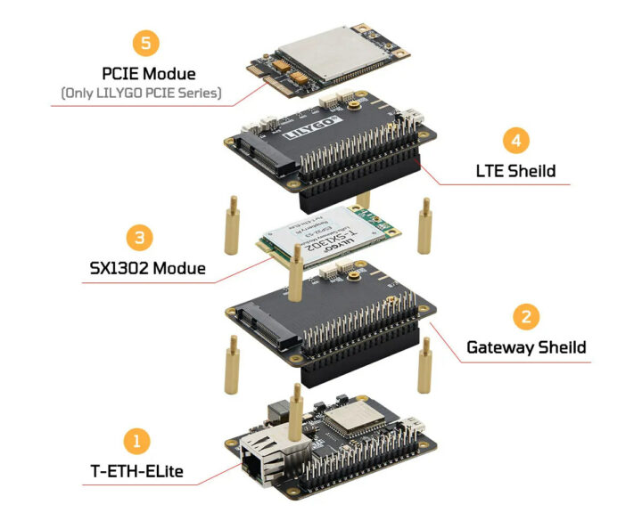
LILYGO T-ETH-Elite is an ESP32-S3-powered IoT board with an Ethernet RJ45 port supporting PoE and a 40-pin GPIO header for stackable shields that offer support for LoRaWAN, 2G, NB-IoT, or/and 4G LTE cellular connectivity.
The ESP32-S3 board allows users to build gateways with Ethernet, WiFi, Bluetooth, GNSS, LoRaWAN, and Cellular (2G, NB-IoT, 4G LTE) connectivity, and they can easily switch cellular modules to match specific requirements.
LILYGO T-ETH-Elite specifications:
Wireless module – Es
LILYGO T-ETH-Elite is an ESP32-S3-powered IoT board with an Ethernet RJ45 port supporting PoE and a 40-pin GPIO header for stackable shields that offer support for LoRaWAN, 2G, NB-IoT, or/and 4G LTE cellular connectivity.
The ESP32-S3 board allows users to build gateways with Ethernet, WiFi, Bluetooth, GNSS, LoRaWAN, and Cellular (2G, NB-IoT, 4G LTE) connectivity, and they can easily switch cellular modules to match specific requirements.
LILYGO T-ETH-Elite specifications:
Wireless module – Espressif ESP32-S3-WROOM-1
MCU – ESP32-S3R8 dual-core Tensilica LX7 up to 240 MHz with 512KB SRAM, up to 8MB PSRAM
Storage – 16MB flash
Connectivity – WiFi 4 and Bluetooth LE 5
PCB antenna
Storage – MicroSD card slot
Networking – 10/100Mbps Ethernet RJ45 port via W5500 SPI to Ethernet chip
USB – USB Type-C port for power and programming
Expansion – 40-pin (mostly) Raspberry Pi-compatible GPIO header for shields (up to 23x GPIO, USB 2.0, UART, 5V, 3.3V, and GND)
Misc
Reset and Boot buttons
User LED (IO38), 5V and 3.3V power LEDs
USB OTG switch
Power Supply
5V/500mA via USB-C port
36V to 57V via PoE (802.3af)
Dimensions – 67 x 50 mm
The T-ETH-Elite board can be fitted with one or more stackable expansion boards connected through the 40-pin GPIO header:
LTE Shield with L76K GPS module and T-PCIe expansion for cellular mPCIe modules from the company:
T-PCIE SIM7000X Series 2G NB-IoT
T-PCIE SIM7020X Series NB-IoT
T-PCIE SIM7600X Series 4G LTE Cat 4
T-PCIE A7608X-H Series 4G LTE Cat 4
T-PCIE A7670X Series 4G LTE Cat 1
Gateway Shield with L76K GPS module and the mPCIe SX1302 LoRa gateway module from the company
LoRa Shield with L76K GPS module and optional LoRa module soldered on the board either LR1121, SX1262, SX1276,SX1280
T-ETH-Elite LTE ShieldT-ETH-Elite LoRa Shield
The T-ETH-Elite Gateway shield looks similar to the LTE shield, except it lacks the SIM card slot, microphone and speaker connectors, and has no DIP switch for LoRa configuration (only a 2-pin DIP switch for GPS). The LTE shield and Gateway shield can be stacked on top of each other, but the LoRa shield cannot. It can only be used directly with the T-ETH-Elite board.
It’s not the first ESP32 Ethernet board with PoE from the company, as we previously covered the T-Internet-POE and T-ETH-Lite ESP32-S3 among others, and they all share the same GitHub repository with a long list of PlatformIO/Arduino samples with client/server, WebSockets, I2C, SPI, etc… Recent commits add code samples specific to the T-ETH-Elite board and shields:
LoRa Shield examples – LoRa_Receive_Interrupt, LoRa_Transmit_Interrupt, factory test sample
Gateway shield test example – T-ETH-Elite-Gateway-Shield
The Quectel LG290P is a quad-band, multi-constellation, high-precision, real-time kinematic (RTK) GNSS module that supports GPS, GLONASS, Galileo, BDS, QZSS, and NavIC constellations. A typical GNSS module like the SparkFun GNSS L1/L5 can receive signals from only one or two frequency bands, but the Quectel module can receive signals from four different frequency bands (L1, L2, L5, and E6) simultaneously and features built-in anti-jamming technology for improved signal reception in challenging e
The Quectel LG290P is a quad-band, multi-constellation, high-precision, real-time kinematic (RTK) GNSS module that supports GPS, GLONASS, Galileo, BDS, QZSS, and NavIC constellations. A typical GNSS module like the SparkFun GNSS L1/L5 can receive signals from only one or two frequency bands, but the Quectel module can receive signals from four different frequency bands (L1, L2, L5, and E6) simultaneously and features built-in anti-jamming technology for improved signal reception in challenging environments. All these measures make this chip suitable for high-precision navigation applications like autonomous robots, UAVs, precision agriculture, surveying and mapping, and autonomous driving.
Interfaces – UART, SPI, I2C (Under development/ in progress)
Power supply: 3.15 – 3.45V
Current consumption – 87 mA (normal operation), 12 uA (power saving)
Dimensions – 16 x 12.2 x 2.6 mm
Weight – 0.9 g
Temperature range: – 40°C to +85°C (operating), -40°C to +90°C (storage)
Certifications – CE, RoHS (Under development/ in progress)
The company mentions that as the module supports an advanced multi-frequency RTK algorithm it enhances the fix rate by 50% and reduces the time to achieve RTK fix to less than five seconds in challenging environments compared to dual-band solutions.
The module also supports integrity monitoring and authentication information verification which helps ensure the accuracy and trustworthiness of its location data, which is crucial for self-driving vehicles or robotic lawnmowers to make safe decisions. Additionally, the module also includes some security features including ECC check and Secure Boot features. More information about the module can be found on the datasheet and the product page of the module, and some additional information can be found on the press release.
Quectel LG290P GNSS module applications
The Quectel LG290P GNSS module is priced at around $82 and is available on DigiKeyMouser and Avnet stores.
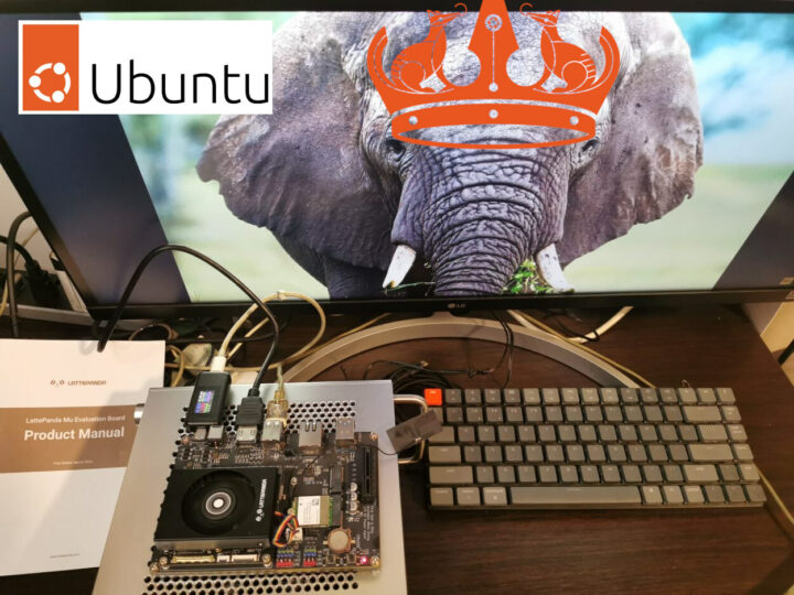
We’ve already checked out the hardware for LattePanda Mu and tested it on Windows 11 using both the Lite Carrier Board and Full-Function Evaluation in the first part of the review. We’ve now had time to test the LattePanda Mu Intel N100 board with Ubuntu 24.04 to see how it performs in Linux with the following tests:
Initial system information
Benchmarks for CPU, disks, peripherals, and networking (GbE and WiFi)
Web and multimedia usage
Power consumption
Since LattePanda Mu is an x86 machine,
We’ve already checked out the hardware for LattePanda Mu and tested it on Windows 11 using both the Lite Carrier Board and Full-Function Evaluation in the first part of the review. We’ve now had time to test the LattePanda Mu Intel N100 board with Ubuntu 24.04 to see how it performs in Linux with the following tests:
Initial system information
Benchmarks for CPU, disks, peripherals, and networking (GbE and WiFi)
Web and multimedia usage
Power consumption
Since LattePanda Mu is an x86 machine, we can create a boot disk from the Ubuntu 24.04 ISO as we would on a PC.
LattePanda Mu – Ubuntu 24.04 system information
The installation went smoothly, and upon completion, we checked basic system information.
Let’s start benchmarks with Thomas Kaiser’s sbc-bench.sh script and the LattePanda Mu fitted with its active cooler:
root@UnoIoT-PC:/home/arnon# sudo ./sbc-bench.sh -r
Starting to examine hardware/software for review purposes...

sbc-bench v0.9.67

Installing needed tools: distro packages already installed. Done.
Checking cpufreq OPP. Done.
Executing tinymembench. Done.
Executing RAM latency tester. Done.
Executing OpenSSL benchmark. Done.
Executing 7-zip benchmark. Done.
Throttling test: heating up the device, 5 more minutes to wait. Done.
Checking cpufreq OPP again. Done (10 minutes elapsed).

Results validation:

  * Measured clockspeed not lower than advertised max CPU clockspeed
  * No swapping
  * Background activity (%system) OK
  * Powercap detected. Details: "sudo powercap-info -p intel-rapl" -> https://tinyurl.com/4jh9nevj

Full results uploaded to https://0x0.st/Xfgy.bin

#  ADL-N  / N100

Tested with sbc-bench v0.9.67 on Mon, 29 Jul 2024 16:59:06 +0700. Full info: [https://0x0.st/Xfgy.bin](http://0x0.st/Xfgy.bin)

### General information:

    Information courtesy of cpufetch:

    Name:                Intel(R) N100
    Microarchitecture:   Alder Lake
    Technology:          10nm
    Max Frequency:       3.400 GHz
    Cores:               4 cores
    AVX:                 AVX,AVX2
    FMA:                 FMA3
    L1i Size:            64KB (256KB Total)
    L1d Size:            32KB (128KB Total)
    L2 Size:             2MB
    L3 Size:             6MB

    N100, Kernel: x86_64, Userland: amd64

    CPU sysfs topology (clusters, cpufreq members, clockspeeds)
                     cpufreq   min    max
     CPU    cluster  policy   speed  speed   core type
      0        0        0      700    3400   Alder Lake
      1        0        1      700    3400   Alder Lake
      2        0        2      700    3400   Alder Lake
      3        0        3      700    3400   Alder Lake

7650 KB available RAM

### Clockspeeds (idle vs. heated up):

Before at 47.0°C:

    cpu0: OPP: 3400, Measured: 3388

After at 80.0°C:

    cpu0: OPP: 3400, Measured: 3387

### Performance baseline

  * memcpy: 10621.5 MB/s, memchr: 17372.4 MB/s, memset: 11022.5 MB/s
  * 16M latency: 120.3 112.7 120.7 112.8 119.8 104.6 99.49 104.0
  * 128M latency: 134.8 133.2 135.0 134.2 135.9 127.1 117.1 117.6
  * 7-zip MIPS (3 consecutive runs): 13671, 13756, 13741 (13720 avg), single-threaded: 3811
  * `aes-256-cbc     894307.23k  1177856.64k  1217782.78k  1227432.28k  1231426.90k  1230908.07k`
  * `aes-256-cbc     903109.40k  1177899.58k  1217397.08k  1227928.92k  1230443.86k  1231071.91k`

### PCIe and storage devices:

  * Intel Alder Lake-N Thunderbolt 4 USB (Onboard - Other): driver in use: xhci_hcd
  * Intel Alder Lake-N PCH USB 3.2 xHCI Host (Onboard - Other): driver in use: xhci_hcd
  * Intel Device 54c4 (Onboard - Other): driver in use: sdhci-pci
  * Realtek RTL8822CE 802.11ac PCIe Wireless Network Adapter: Speed 2.5GT/s, Width x1, driver in use: rtw_8822ce,
  * Realtek RTL8111/8168/8211/8411 PCI Express Gigabit Ethernet: Speed 2.5GT/s, Width x1, driver in use: r8169,
  * 58.2GB "Samsung CUTA42" HS400 Enhanced strobe eMMC 5.1 card as /dev/mmcblk0: date 02/2022, manfid/oemid: 0x000015/0x0100, hw/fw rev: 0x0/0x0100000000000000
  * Winbond W25Q128 16MB SPI NOR flash, drivers in use: spi-nor/intel-spi

### Swap configuration:

  * /swap.img on /dev/mmcblk0p2: 4.0G (0K used) on MMC storage

### Software versions:

  * Ubuntu 24.04 LTS (noble)
  * Compiler: /usr/bin/gcc (Ubuntu 13.2.0-23ubuntu4) 13.2.0 / x86_64-linux-gnu
  * OpenSSL 3.0.13, built on 30 Jan 2024 (Library: OpenSSL 3.0.13 30 Jan 2024)

### Kernel info:

  * `/proc/cmdline: BOOT_IMAGE=/boot/vmlinuz-6.8.0-39-generic root=UUID=d7c7dea8-d8ba-4994-8ee2-6ce309f2d96f ro quiet splash vt.handoff=7`
  * Vulnerability Reg file data sampling: Mitigation; Clear Register File
  * Vulnerability Spec store bypass:      Mitigation; Speculative Store Bypass disabled via prctl
  * Vulnerability Spectre v1:             Mitigation; usercopy/swapgs barriers and __user pointer sanitization
  * Kernel 6.8.0-39-generic / CONFIG_HZ=1000

Waiting for the device to cool down........... 39.0°C

All known settings adjusted for performance. Device now ready for benchmarking.
Once finished stop with [ctrl]-[c] to get info about throttling, frequency cap
and too high background activity all potentially invalidating benchmark scores.
All changes with storage and PCIe devices as well as suspicious dmesg contents
will be reported too.

Time        CPU    load %cpu %sys %usr %nice %io %irq   Temp
16:59:28: 2900MHz  2.64  35%   0%  34%   0%   0%   0%  53.0°C
17:00:28: 3186MHz  1.02   0%   0%   0%   0%   0%   0%  34.0°C
17:01:29: 3064MHz  0.43   0%   0%   0%   0%   0%   0%  33.0°C
17:02:29: 3102MHz  0.16   0%   0%   0%   0%   0%   0%  34.0°C
17:03:29: 2917MHz  0.06   0%   0%   0%   0%   0%   0%  33.0°C
17:04:29: 3100MHz  0.02   0%   0%   0%   0%   0%   0%  34.0°C
17:05:29: 3097MHz  0.00   0%   0%   0%   0%   0%   0%  35.0°C
17:06:29: 3311MHz  0.00   0%   0%   0%   0%   0%   0%  35.0°C
17:07:29: 3216MHz  0.05   0%   0%   0%   0%   0%   0%  34.0°C

Cleaning up. Done.
Checking cpufreq OPP again. Done.

Clockspeeds now at 51.0°C:

    cpu0: OPP: 3400, Measured: 3387

Results validation:

  * Measured clockspeed not lower than advertised max CPU clockspeed
  * No swapping
  * Background activity (%system) OK
  * Powercap detected. Details: "sudo powercap-info -p intel-rapl" -> https://tinyurl.com/4jh9nevj
The CPU temperature goes up 84°C with the 7-zip multi-core benchmark, and the CPU frequency gradually drops to around 2,900 MHz at 75°C, while it was 3,100 MHz at 60°C and gradually decreases to 2,900 MHz when the temperature is over 75°C showing active cooler is sufficient to cool the system, but power limits come into play. The test room was at an ambient temperature of approximately 29°C and the fan was working all the time during the test.
We’ll use iozone3 to test the eMMC flash performance with parameters to disable caching:
root@UnoIoT-PC:/home/arnon# sudo iozone -e -I -a -s 512M -r 1024k -r 16384k -i 0 -i 1 -i 2
        Iozone: Performance Test of File I/O
                Version $Revision: 3.506 $
                Compiled for 64 bit mode.
                Build: linux-AMD64
                                                                    random    random      bkwd     record     stride
              kB  reclen    write    rewrite      read    reread      read     write      read    rewrite       read    fwrite  frewrite     fread   freread
          524288    1024    103772    107436    295798    294323    296530    106148
          524288   16384    107652    106822    307988    308700    309198    107570

iozone test complete.
The 64GB eMMC flash achieved around 301 MB/s for reads, and around 104 MB/s for writes within the stated speeds of eMMC 5.1 flash.
We repeated the test with the same WD_BLACK SN770 NVMe SSD as used in Windows:
Command line used: iozone -e -I -a -s 512M -r 1024k -r 16384k -i 0 -i 1 -i 2
                                                                    random    random      bkwd     record     stride
              kB  reclen    write    rewrite      read    reread      read     write      read    rewrite       read    fwrite  frewrite     fread   freread
          524288    1024   1888958   1850547   2903661   2451318   2587007   1894214
          524288   16384   1826768   1887713   3138602   3144076   3143191   1934963

iozone test complete.
The WD_BLACK SN770 NVMe SSD supports PCIe Gen 4.0 x4 with a sequential read speed of up to 4,000 MB/s and a sequential write speed of up to 2,000 MB/s. However, since the LattePanda Mu board only supports PCIe 3.0 x4 due to the Intel N100 SoC’s limitation, and the measured read speed is around 2.994 GB/s and the write speed is 1.742 GB/s, very similar to the results we got with CrystalDiskMark benchmarks on Windows 11.
Web browsing performance
We’ll use Speedometer 2.0 to check the performance of each web browser. On Ubuntu 24.04, only Firefox comes pre-installed by default, and so we installed Chromium ourselves.
Chromium
181 runs per minute on Chromium is about 12% higher than the score on Firefox (160 runs per minute)
We tested with the board with the glmark2-es2-wayland command to test the performance. The glmark2-es-wayland score is 3,220 points higher than the Raspberry Pi 5 (2,036 points), but lower than the RK3588-based NanoPi R6S SBC which scored as high as 4,500 points.
arnon@UnoIoT-PC:/media/arnon/New Volume$ glmark2-es2-wayland
=======================================================
    glmark2 2023.01
=======================================================
    OpenGL Information
    GL_VENDOR:      Intel
    GL_RENDERER:    Mesa Intel(R) Graphics (ADL-N)
    GL_VERSION:     OpenGL ES 3.2 Mesa 24.0.9-0ubuntu0.1
    Surface Config: buf=32 r=8 g=8 b=8 a=8 depth=24 stencil=0 samples=0
    Surface Size:   800x600 windowed
=======================================================
[build] use-vbo=false: FPS: 2723 FrameTime: 0.367 ms
[build] use-vbo=true: FPS: 2849 FrameTime: 0.351 ms
[texture] texture-filter=nearest: FPS: 3446 FrameTime: 0.290 ms
[texture] texture-filter=linear: FPS: 3950 FrameTime: 0.253 ms
[texture] texture-filter=mipmap: FPS: 3847 FrameTime: 0.260 ms
[shading] shading=gouraud: FPS: 2339 FrameTime: 0.428 ms
[shading] shading=blinn-phong-inf: FPS: 3080 FrameTime: 0.325 ms
[shading] shading=phong: FPS: 3977 FrameTime: 0.251 ms
[shading] shading=cel: FPS: 3761 FrameTime: 0.266 ms
[bump] bump-render=high-poly: FPS: 2439 FrameTime: 0.410 ms
[bump] bump-render=normals: FPS: 6197 FrameTime: 0.161 ms
[bump] bump-render=height: FPS: 4713 FrameTime: 0.212 ms
[effect2d] kernel=0,1,0;1,-4,1;0,1,0;: FPS: 3135 FrameTime: 0.319 ms
[effect2d] kernel=1,1,1,1,1;1,1,1,1,1;1,1,1,1,1;: FPS: 1341 FrameTime: 0.746 ms
[pulsar] light=false:quads=5:texture=false: FPS: 5095 FrameTime: 0.196 ms
[desktop] blur-radius=5:effect=blur:passes=1:separable=true:windows=4: FPS: 1249 FrameTime: 0.801 ms
[desktop] effect=shadow:windows=4: FPS: 2600 FrameTime: 0.385 ms
[buffer] columns=200:interleave=false:update-dispersion=0.9:update-fraction=0.5:update-method=map: FPS: 828 FrameTime: 1.208 ms
[buffer] columns=200:interleave=false:update-dispersion=0.9:update-fraction=0.5:update-method=subdata: FPS: 1421 FrameTime: 0.704 ms
[buffer] columns=200:interleave=true:update-dispersion=0.9:update-fraction=0.5:update-method=map: FPS: 1050 FrameTime: 0.953 ms
[ideas] speed=duration: FPS: 3296 FrameTime: 0.303 ms
[jellyfish] <default>: FPS: 2420 FrameTime: 0.413 ms
[terrain] <default>: FPS: 216 FrameTime: 4.645 ms
[shadow] <default>: FPS: 3549 FrameTime: 0.282 ms
[refract] <default>: FPS: 523 FrameTime: 1.914 ms
[conditionals] fragment-steps=0:vertex-steps=0: FPS: 4548 FrameTime: 0.220 ms
[conditionals] fragment-steps=5:vertex-steps=0: FPS: 4497 FrameTime: 0.222 ms
[conditionals] fragment-steps=0:vertex-steps=5: FPS: 4554 FrameTime: 0.220 ms
[function] fragment-complexity=low:fragment-steps=5: FPS: 4533 FrameTime: 0.221 ms
[function] fragment-complexity=medium:fragment-steps=5: FPS: 4551 FrameTime: 0.220 ms
[loop] fragment-loop=false:fragment-steps=5:vertex-steps=5: FPS: 4531 FrameTime: 0.221 ms
[loop] fragment-steps=5:fragment-uniform=false:vertex-steps=5: FPS: 4552 FrameTime: 0.220 ms
[loop] fragment-steps=5:fragment-uniform=true:vertex-steps=5: FPS: 4513 FrameTime: 0.222 ms
=======================================================
                                  glmark2 Score: 3220
=======================================================
Note that glmark2-es2-wayland can be useful to compare Arm and x86 boards, but considering GPUs on x86 usually support OpenGL (instead of just OpenGL ES), it may not be relevant when comparing with other x86 platforms or overall graphics performance.
WebGL Aquarium
So let’s switch to the WebGL aquarium demo on Chromium where the LattePanda Mu achieved 37 fps with 30,000 fish. This compares to 31 fps with 5,000 fish on the NanoPi R6S SBC.
Video playback with YouTube and local file
A 4K 30 FPS video could play in Chromium without any frames dropped.
Switching to a 4K 60 FPS video played with some minimal stuttering barely noticeable to the eye, and the “Stats for Nerds” overlay reported about 4.5% of frames dropped.
We then played an H.264 1920 x 1080 video with VLC, it can be played well with very few dropped frames.
Note that the fan runs at full speed as soon as we start playing a video, in this case, a “Big Bug Bunny” sample. The audio worked fine as well through HDMI.
A 4Kp30 H.265 file played without any lag and very few dropped frames were reported in the Statistics tab of the Media Information window.
Networking performance
We used the iperf3 utility to test gigabit Ethernet and Wi-Fi networking using the iperf3 program. Note the Full-Function Evaluation board supports 2.5Gbps Ethernet, but we only had a gigabit Ethernet switch for this review, so it was only tested at 1Gbps. A Xiaomi Router AX3200 router was used for testing.
Note the LattePanda Mu does not come with built-in WiFi, we used an M.2 RTL8822CE (Wi-Fi 5) module for testing.
Checking out the GPIO in Linux
DFRobot provides very little information from LattePanda Mu’s GPIO, UART, I2C, and SPI. We just know the board offers the following interfaces:
4x UART
4x I2C
Up to 64x GPIO
What’s missing is a document that clearly explains how to use those. All we have is the Dev Status page that shows some interfaces are not supported yet (including GPIO!), but I2C, SPI, and UART can already be used. We’ll try our best to test it out I2C, by first checking whether I2C devices are listed:
We then installed the i2c-tools utility to check the I2C information for several I2C devices of the LattePanda Mu, and I2C-5 and I2C-7 show some connected devices.
We tried to connect an I2C proximity sensor to the board, but it was not detected. We need to wait for more information from DFRobot for further testing, and we did not test the UART and GPIO sections.
LattePanda Mu’s power consumption with Ubuntu 24.04
The LattePanda Mu’s power consumption in Linux (Ubuntu 24.04) was measured with a USB power meter.
Power off – 0.33 Watt
Booting – 9.9 Watts
Idle – 5.6 Watts (connected to HDMI, WiFi, Ethernet only)
YouTube 4K 60FPS in Chromium (fullscreen) – 20 Watts on average
7-Zip Benchmark (multi-core) – 22 Watts on average
Conclusion
The Intel N100-powered Lattepanda Mu SBC works well with Ubuntu 24.04. It supported all peripherals we tried since all necessary drivers are available. The Ubuntu 24.04 performance test results were close to those on Windows 11.
There were a few downsides too. First, we failed to install the board in a mini-ITX case because the Full Carrier board is in the mini-ITX form factor, but the layout of the ports did not meet the motherboard standards, so it could not be assembled in the specific case we tried. Then GPIO support and related documentation are close to inexistent, so we could not test it properly. We may update the review once additional details are provided by DFRobot/LattePanda.
The LattePanda Mu Compute Module can be especially useful to companies designing custom products, as they only need to design a custom carrier board with a 260-pin SO-DIMM connector for the CPU module and route signals such as USB, PCIe, and GPIOs.
We’d like to thank DFRobot for sending the LattePanda Mu module, carrier boards, and accessories for review. The LattePanda Mu x86 Compute Module can be purchased for $139 on DFRobot, but most people will first purchase a complete kit that can be customized, and for instance, a kit with the LattePanda Mu SoM, Full-Function carrier board, heatsink, and 19W/90A power supply can be had for $274.90. Alternatively, you’ll find a $199 kit on Amazon with the SoM, Lite carrier board, and active cooler.
The Jetway JMTX-ADN8 is a mini-ITX motherboard built around an Intel N97 (Alder Lake-N) processor. The board supports up to 32GB DDR5 RAM via a single SO-DIMM slot and can drive up to three independent displays powered by Intel UHD graphics. Additionally, it offers dual GbE LAN, nine USB ports both USB3.2 Gen 1 and USB 2.0, and multiple storage and expansion options including M.2 (M-key, E-key, and B-key) and SATA-III. The motherboard also includes PCI expansion and supports Windows and Linux op
The Jetway JMTX-ADN8 is a mini-ITX motherboard built around an Intel N97 (Alder Lake-N) processor. The board supports up to 32GB DDR5 RAM via a single SO-DIMM slot and can drive up to three independent displays powered by Intel UHD graphics. Additionally, it offers dual GbE LAN, nine USB ports both USB3.2 Gen 1 and USB 2.0, and multiple storage and expansion options including M.2 (M-key, E-key, and B-key) and SATA-III. The motherboard also includes PCI expansion and supports Windows and Linux operating systems.
In one of our last posts, we wrote about the Jetway JNUC-ADN1, another Intel N97-powered SBC, but in a smaller Next Unit of Computing (NUC) form factor. Other than that we have written about similar motherboards in mini-ITX from factors including Radxa ROCK 5 ITX, MW-100-NAS, and ASRock IMB-A8000 feel free to check those out if you are looking for mini-ITX motherboards.
Jetway JMTX-ADN8 Mini ITX Motherboard Block Diagram
In terms of software, this N97-powered mini-ITX motherboard supports Linux, Windows 10, and Windows 11 operating systems with relevant drivers available in the download section of the product page along with a datasheet.
Jetway JMTX ADN8 Specifications
At the time of writing the company has not provided any pricing information for the Jetway JNUC-ADN1 Intel N97 mini-ITX motherboard. More details, including drivers and order-related information, can be found on the product page.
Forlinx FET3576-C SoM is a new System-on-Module built around the Rockchip RK3576 SoC which features four Arm Cortex-A72 and four Cortex-A53 cores made from a 22nm lithography process. The SoM is available with 2GB or 4GB of LPDDR4 RAM option and can be equipped with up to 32GB of eMMC storage. Additionally, it has 6 TOPS NPU power and supports standard peripherals like GbE Ethernet, Wifi, Bluetooth, LVDS, MIPI DSI, and much more. All these features make this device useful for IoT, edge computing
Forlinx FET3576-C SoM is a new System-on-Module built around the Rockchip RK3576 SoC which features four Arm Cortex-A72 and four Cortex-A53 cores made from a 22nm lithography process. The SoM is available with 2GB or 4GB of LPDDR4 RAM option and can be equipped with up to 32GB of eMMC storage. Additionally, it has 6 TOPS NPU power and supports standard peripherals like GbE Ethernet, Wifi, Bluetooth, LVDS, MIPI DSI, and much more. All these features make this device useful for IoT, edge computing, digital signage, and many other applications.
The new FET3576-C SoM and its OK3576-C development board look very similar to the Forlinx FET3562J-C SoM and related board we covered earlier this month. But the main difference between the two is that the new one is built with the RK3576 SoC whereas the old one is built around the Rockchip RK3562(J) SoC. Previously we also saw that the RK3576 SoC was used in products like Banana Pi BPI-M5 Pro, Mekotronics R57, and others. Feel free to check those out if you are interested in those topics.
WiFi and BT – 1x AW-CM358SM-WIFI&BT, supports 2.4G/5G WiFi and BT 5.0
USB
3× Type-A USB connectors, supports HS mode (480Mbps), FS mode (12Mbps), and LS mode (1.5Mbps)
1x Type-C connector, work together with DP TX
Expansion
2x CAN and CAN-FD, with built-in transceivers
1x PCIe x1 slot, up to 5Gbps
2x RS485 interfaces with galvanic isolation
5x ADC with 1.27mm pin headers
1x UART 2.54mm header
1x RTC
8x GPIO with standard 2.54mm headers
Power – 12V
Dimensions – Not Mentioned
Forlinx OK3576-C Carrier Board with SoMForlinx FET3576-C SoM with 4x 100-pin high-density connectors
As the SoM is powered by a Rockchip RK3576 SoC, it should support OpenGL ES 1.1/2.0/3.2, OpenCL 2.0, and Vulkan 1.1. However, the company does not mention it on their products page or datasheet of the device.
In terms of software, the SoM is compatible with Linux 6.1.57 and Android and supports multi-task and multi-scenario parallel processing, as well as deep learning frameworks such as TensorFlow, Caffe, Tflite, Pytorch, Onnx NN, Android NN, and others.
FlexBus Block Diagram
The SoM also supports a new parallel bus interface which the company calls “FlexBus”. It is a flexible parallel bus interface that can emulate various protocols and support 2/4/8/16-bit data transmission with a clock speed of up to 100MHz. It offers diverse bus transfer interfaces like DSMC, CAN-FD, PCIe 2.1, SATA 3.0, USB 3.2, SAI, I2C, I3C, and UART.
More details about the SoM and the development board can be found on the announcement and the product page. However, at the time of writing the company has not provided any pricing information.
The Seeed Studio Wio Tracker 1110 is a dev kit designed to work with the Meshtastic network. The board is built around a Nordic nRF52840 multiprotocol Bluetooth 5.4 SoC and uses the Semtech LR1110 LoRa transceiver for communication. Seeed Studio is selling the Wio Tracker 1110 development board in a bundle with an OLED display and a GNSS receiver, providing everything needed to start experimentation for peer-to-peer LoRa mesh networking.
Meshtastic is a free, open-source, decentralized mesh netw
The Seeed Studio Wio Tracker 1110 is a dev kit designed to work with the Meshtastic network. The board is built around a Nordic nRF52840 multiprotocol Bluetooth 5.4 SoC and uses the Semtech LR1110 LoRa transceiver for communication. Seeed Studio is selling the Wio Tracker 1110 development board in a bundle with an OLED display and a GNSS receiver, providing everything needed to start experimentation for peer-to-peer LoRa mesh networking.
Meshtastic is a free, open-source, decentralized mesh network that uses LoRa radios to establish a low-power, long-range, off-grid communication system in areas without reliable infrastructure. Driven entirely by the community, Meshtastic enables decentralized, encrypted communication without the need for a dedicated router or phone.
Previously we have written various versions of the Wio Tracker including the Wio GPS and Wio LTE GPS Tracker. Since Meshtastic projects are becoming popular among developers and enthusiasts, we will likely see many more dev kits with Meshtastic support.
LoRa/(G)FSK Half-Duplex RF transceiver working in the 1863~928 (chip antenna or u.FL connector for external antenna)
Compatible with LoRaWAN 1.0.4 standard
GNSS (GPS/ BeiDou) low-power scanning (chip antenna or u.FL connector for external antenna)
802.11b/g/n Wi-Fi ultra-low-power passive scanning with onboard chip antenna
Range – 2~10km (depends on antenna and environment)
Onboard Sensors
TH Sensor (SHT41)
Temperature: -40~85°C, ±0.2°C
Humidity – 0~100%RH, ±1.8%RH
3-Axis Accelerometer (Not Used)
Range – ±2g, 4g, 8g, 16g
Bandwidth – 0.5Hz ~ 625Hz
Sensitivity (LSB/g) – 1000 (±2g) to 83 (±16g)
Grove GPS Air530 (External Sensor)
Supply voltage – 3.3V/5V
Operating current – up to 60mA
Temperature
Operating: -35°C to 85°C
Storage: -55°C to 100°C
Display – Grove 0.96 inch OLED display
Supply voltage – 3.3 / 5V
Driver IC – SSD1308Z
Display – White, 128×64 Dot Matrix
Panel size – 26.7×19.26 mm, Active Area – 21.74×11.175 mm
Operating temperature: -20~70 ℃
USB – USB-C for power and programming
Grove Interface
3x Digital Interface
1x ADC
1x I2C
1x UART
Misc
Battery connector for 3.7V battery
Reset button
User button
User LED
Power LED
Charge status indicator LED
Supply voltage – 5V with USB-C connector
Dimensions – Not specified
The board is completely open-sourced so the company provides all necessary documentation including the datasheet, Eagle CAD file, and datasheet for the modules on Seeed Studio’s products page. The Meshtastic firmware on the other hand is available on the company’s GitHub repository. For those of you who already own a Wio Tracker 1110, you’ll need the Air530 GPS receiver and the OLED, and follow the instructions to update the firmware.
The company also provides design files for an acrylic enclosure and a 3D-printed enclosure which Seeed Studio mentions will be available for purchase once the company gets enough feedback from the users.
ODrive Micro is a high-performance servo motor drive from ODrive Robotics that comes in an ultra-compact, 32 x 32mm form factor. The controller provides up to 100W continuous power for driving brushless servo motors.
The ODrive Micro is the latest in a series of motor controllers from ODrive and builds on the company’s established software and hardware ecosystem. This includes support for CAN Bus, programming libraries, and a web-based graphic user interface for easy and intuitive setup.
The Mi
ODrive Micro is a high-performance servo motor drive from ODrive Robotics that comes in an ultra-compact, 32 x 32mm form factor. The controller provides up to 100W continuous power for driving brushless servo motors.
The ODrive Micro is the latest in a series of motor controllers from ODrive and builds on the company’s established software and hardware ecosystem. This includes support for CAN Bus, programming libraries, and a web-based graphic user interface for easy and intuitive setup.
The Micro features a CAN interface for daisy-chaining other controllers and an onboard 12-bit magnetic encoder for direct mounting without needing an external encoder. It also offers the option to mount hall, quadrature, and SPI external encoders via the J1 header on the board.
The ODrive Micro is aimed at robotics applications where space is premium, including hobbyist and professional use. It is similar to the Wukong 2040, ClearCore, and the Serial Bus Servo Driver HAT.
ODrive Micro specifications:
Supported Motor Types – BLDC, PMAC
Operation
Commutation – FOC (field-oriented control)
Voltage Range – 10 – 30V (32V max)
Current – 3.5A continuous (7V peak)
Power – 100W continuous (180W peak)
Onboard 12-bit magnetic encoder
Interfaces – USB-C, CAN
Supports external hall, incremental, and SPI encoders
Control modes – Torque, velocity, position, and trajectory
Dimensions – 32 x 32 x 7.5 mm
Mass – 6.8 grams
The ODrive Micro compares favorably to alternatives such as the Tinymovr M5.2, Moteus C1, and DENALI XCR-C. It is more affordable, compact, and offers extensive documentation.
It is also completely open-source. The schematics still need to be published but the CAD models are available on Onshape. The software suite, including the Python library, CAN communication protocols, Arduino sample code, and all other associated files will be made available after campaign orders have been fulfilled. Additional information is available in the datasheet for the Micro module and documentation (for older ODrive modules).
The Micro is currently live on CrowdSupply and the campaign has surpassed its funding goal with several days left. You can get the motor controller board for $79 ($89 once the campaign ends) and a shipping fee of $8 within the United States and $18 to the rest of the world. The company has also listed add-ons for sale, including a $39 USB-CAN adapter plus cable, a $16 USB isolator with cable, a $9 wire harness kit, and $6 CAN cables.
The Adeept Robot HAT V3.0 is a motor and sensor driver HAT that supports Raspberry Pi 5, Pi 4, and Pi 3 models. The board features a bunch of headers that give access to sensor and motor controllers including sixteen servo motor ports, a three-channel line tracking sensor, an ultrasonic sensor, IR receivers, WS2812 RGB LEDs, and more. Additionally, the board features an integrated 8.4V battery charger with a Type-C port for charging. All these features make it easy to build DIY robotics and smar
The Adeept Robot HAT V3.0 is a motor and sensor driver HAT that supports Raspberry Pi 5, Pi 4, and Pi 3 models. The board features a bunch of headers that give access to sensor and motor controllers including sixteen servo motor ports, a three-channel line tracking sensor, an ultrasonic sensor, IR receivers, WS2812 RGB LEDs, and more. Additionally, the board features an integrated 8.4V battery charger with a Type-C port for charging. All these features make it easy to build DIY robotics and smart car projects with this HAT.
Power – 1x 8.4V battery power input port with charger
Dimensions – Not Mentioned (Raspberry Pi HAT compatible)
For simplicity, Adeept provides a full interface diagram of the control board which makes the assembly process very easy. However, the board lacks all the specifications for the various ICs that are used throughout the board. The diagram showcased only PCA9685 which is a 16-channel servo motor driver IC.
After searching for a little bit I found a GitHub repo containing some Python code for Adeept RaspTank built around the HAT. While searching I also found an Amazon listing for the Adeept RaspTank Smart Robot Kit which costs around $79.99. Additionally, I found the Adeept PiCar-B Mars Rover Smart Car Kit on Amazon which also uses the Adeept Robot HAT as the main driver. The Adeept RaspTank and the Adeept PiCar-B Mars Rover are also available on Aliexpress where they sell for around $96 and $87 respectively.
Adeept PiCar-B Mars Rover Smart Car Kit with Robot HAT v3.0
SunFounder has sent me a review sample of the Pironman 5 tower PC case for the Raspberry Pi 5. I had already reviewed the Pironman case for Raspberry Pi 4 last year, so I’ll do something similar this time around with the new Pironman 5 case adding support for NVMe SSD using the PCIe interface from the Pi 5 SBC.
The Pironman 5 review will include unboxing and an assembly guide, followed by software installation and features testing (e.g. OLED display, RGB LED control, remote control. soft power
The Pironman 5 review will include unboxing and an assembly guide, followed by software installation and features testing (e.g. OLED display, RGB LED control, remote control. soft power off, etc…), before testing the cooling efficiency of the device with some benchmarks.
Pironman 5 unboxing
The Pironman 5 comes in a package that will be smaller than most people expect.
The main features are listed on the side with 5V/5A power input, a 0.96-inch OLED, a tower cooler, M.2 NVMe SSD support, an IR receiver, a CR1220 battery (included), four RGB LEDs, and the dimensions of the tiny tower PC case.
There are a few more accessories than in the original Pironman case due to the extra adapter and expansion boards.
The kit includes an assembly guide, the metal enclosure itself, two RGB fans with black dust filters, an OLED display, a hex key and screwdriver, a tower cooler, FPC PCIe cables, a power button, acrylic plates, various expansion/adapter boards, screws, standoffs, and other tidbits.
The Prionman 5 NVMe PiP board is designed to connect an M.2 NVMe SSD through the PCIe interface of the Raspberry Pi 5. It supports 2230, 2242, 2260, and 2280 SSDs. The Pironman 5 IO HAT+ board allows us to easily access the 40-pin GPIO header from the outside, controls the fans, and features an IR receiver and four RGB LEDs. The Pi 5 USB HDMI adapter moves the micro HDMI and USB-C ports to the rear panel with all other ports and exposes two full-size HDMI ports plus the USB-C port for power. It also includes a CR1220 battery socket and connector for the RTC. Finally, the microSD extender simply changes the location of the microSD card socket so that it can be easily accessed by users.
The Pi 5 Power Switch Convertor relies on two Pogo pins to connect to the Raspberry Pi 5 and a 2-pin connector for the power button.
The enclosed guide lists all components and provides a 28-step assembly guide. You’ll find it with other information on the online tutorial available in English, German, and Japanese.
Pironman 5 case assembly with Raspberry Pi 5 and M.2 NVMe SSD
The Raspberry Pi 5 is not included so you’ll need to bring your own. Last time around, I used my Raspberry Pi 5 with a Cytron MAKERDISK SSD and the active cooler, so I had to remove all that to start with a “clean” Raspberry Pi 5 without thermal pads, heatsink, or HAT. The Pironman 5 works with multiple operating systems, but Raspberry Pi OS is recommended since it’s fully compatible with the Pironman 5 enclosure:
Raspberry Pi OS 64-bit Desktop / Lite) – Perfectly compatible
Ubuntu Desktop 23.10 – No SPI so the RGB LEDs do not light up
Kali – No I2C, so the OLED screen does not work
Home Assistant – Cannot enable I2C and SPI
[Update July 29, 2024: I was told the information above was outdated. Here’s the current OS support status:
Raspberry Pi OS 32-bit/ 64-bit Desktop / Lite) – Perfectly compatible
Home Assistant – perfectly compatible (the documentation comes with Home Assistant-specific instructions)
Homebrigde – perfectly compatible
]
For this review, I’ll reuse the 256 GB Cytron MAKERDISK SSD with Raspberry Pi OS preinstalled. The first step of the assembly is to disassemble the metal case into two parts by removing a few screws and then installing M2.5 standoffs of different heights by carefully following the instructions in the assembly guide. Each standoff, nut, and screw types are in different bags each clearly marked, so assembly will be straightforward. Note that there are also a few spares, and if some screws fall on the ground that’s not a big issue.
Let’s now insert the Pi 5 USB HDMI Adapter and microSD expender into our Raspberry Pi 5 board, insert the provided CR1220 battery, and connect the PCIe and RTC battery cables as shown in the photo below. Note the orientation of the FPC PCIe cable is important.
The next step is to install the power button in the case, and faster the Raspberry Pi 5 and adapter to the metal case with some standoffs. I truly like the hex key (bottom left) designed for the standoffs as it makes assembly so much easier for people with fat fingers.
We’ll now add the three thermal pads on top of the BCM2712 SoC, wireless module, and VLI chip on the Raspberry Pi 5 because insert the tower cooler using the plastic bits with spring.
The 4-pin fan wire needs to be connected to the fan connector on the Raspberry Pi 5. At this point, we can attach the Pi 5 Power Switch Convertor making sure its pogo pins are aligned properly with the power button pins, and secure it with two screws. We can also connect the 2-pin wire from the power button.
The next step is optional and only needed if you plan to use an NVMe SSD. It’s not needed if you’re going to run Raspberry Pi OS from a microSD card. I installed one of the SSD studs in the 2242 location before securing a 256GB Cytron MAKERDISK NVMe SSD.
I then had to slot it on the 4-pin header and secure it with two screws (bottom left and right) and a black plastic rivet in the middle of the Pi 5 Power Switch Convertor.
We can now switch to the other metal part of the Pironman 5 enclosure and install the two fans with dust filters (black) as shown in the image below.
One acrylic plate needs to be installed on the Pironman 5 IO HAT+ after removing the protective films on both sides of the plate. It is secure by two plastic rivet.
We can now connect the two fans and the OLED display…
Before inserting the IO HAT+ into the 40-pin GPIO header of the Raspberry Pi 5, and placing both metal parts together.
The OLED display comes with a 3M sticker, and I initially placed it on the metal case before assembling the two parts. That was a mistake in hindsight, so I had to remove it and assemble the two metal parts before sticking the OLED on the enclosure.
Everything is secured in place with plenty of M2.5 screws. The final step is the installation of the two remaining acrylic plates.
When I first removed the protective film from the larger acrylic plate, I noticed the markings around the GPIO opening still had some brown sticker.
I cleaned it up with a sponge and fingernails.
I could not complete the Pironman 5 assembly with the two acrylic plates securing them with four M2.5 screws each. The result is pretty neat and I find the design prettier than the original Pironman case.
It took me around one hour to complete the assembly.
Software installation
If I connect an Ethernet cable, HDMI display, and the 5V/5A power supply from Raspberry Pi, the system will boot to Raspberry Pi OS. But the OLED does not show anything, the RGB LEDs on the Pironman 5 IO HAT+ are off, and if I press the power button once the popup with shutdown, reboot, and logout will show up, and pressing again will turn off the system, but the fans will be still be rotating.
I can still press the button for 5 seconds for a hard shutdown after which the fan and associated RGB LEDs turn off. That’s because I haven’t installed the necessary software yet. So Let’s do that now.
The first step is to configure the Raspberry Pi 5 to deactivate GPIO power when shutting down the system in order to turn off the OLED screen and RGB fans. We’ll need to manually edit the EEPROM configuration file with the following command:
sudo rpi-eeprom-config -e
Then we can modify the POWER_OFF_ON_HALT line and set it to 1. For instance:
Once the installation is complete (no reboot necessary) the following happens:
The OLED displays CPU, RAM, Disk Usage, CPU Temperature, and the Raspberry Pi’s IP Address.
The four WS2812 RGB LEDs will light up in blue in breathing mode.
The RGB fans will stop and only activate when the CPU temperature reaches 60°C
I have both Ethernet and WiFi configured on my Pi 5, so the display will display both IP addresses in turns every few seconds. The display is really small, my old eyes find it hard to read, so I have to move closer for it to be readable.
If I press the button twice, the Raspberry Pi 5 will turn off, and so will the fans and RGB LEDs. The only thing remaining is the red LED from the Raspberry Pi.
The pironman5.service will start automatically each time you start your Raspberry Pi 5. It does take some CPU resources, but nothing significant.
At this point would have a fully working system, and there’s nothing else you need to do. That’s unless you want to monitor the system and/or change a few settings. This can be done in the Pironman 5 dashboard accessible from http://<IP_Address>:34001. You’ll find five widgets for the fan and CPU temperature, storage, memory, networking, and processor usage.
The second tab “History” allows you to see the chart of various parameters over several lengths of times from 5 minutes and up.
CPU temperature chart in Pironman Dashboard
The third tab provides access to logs for the fan, RGB LEDs, OLED display, power management, etc…
Finally, the gear icon on the right gives access to the Settings. We can enable/disable dark mode and select the temperature unit between °C and °F. Fan mode sets the fan from quiet up to always on. The remaining settings are for the RGB LEDs to enable them, and change the default color, brightness, style, and speed.
There are eight RGB styles: None, Solid, Breathing, Flow, Flow Reverse, Rainbow, Rainbow Reverse, and Hue cycle.
I set the RGB style to Rainbow and the speed to 100% to show what it looks like in the video below.
It’s an improvement over the original Pironman case for Raspberry Pi 4 whose fan and RGB LEDs could only be controlled from the command line, at least at the time of the (March 2023) review.
Talking about the command line, users can still control the RGB LEDs and fans from the Pironman5 client utility, for instance, to integrate some commands into a script:
pi@raspberrypi:~ $ sudo pironman5 --help
usage: pironman5-service [-h] [-c] [-rc [RGB_COLOR]] [-rb [RGB_BRIGHTNESS]]
                         [-rs [{solid,breathing,flow,flow_reverse,rainbow,rainbow_reverse,hue_cycle}]]
                         [-rp [RGB_SPEED]] [-re [RGB_ENABLE]]
                         [-rl [RGB_LED_COUNT]] [-u [{C,F}]]
                         [-gm [GPIO_FAN_MODE]] [-gp [GPIO_FAN_PIN]]
                         [--background [BACKGROUND]]
                         [{start,restart,stop}]

Pironman5

positional arguments:
  {start,restart,stop}  Command

options:
  -h, --help            show this help message and exit
  -c, --config          Show config
  -rc [RGB_COLOR], --rgb-color [RGB_COLOR]
                        RGB color in hex format without # (e.g. 00aabb)
  -rb [RGB_BRIGHTNESS], --rgb-brightness [RGB_BRIGHTNESS]
                        RGB brightness 0-100
  -rs [{solid,breathing,flow,flow_reverse,rainbow,rainbow_reverse,hue_cycle}], --rgb-style [{solid,breathing,flow,flow_reverse,rainbow,rainbow_reverse,hue_cycle}]
                        RGB style
  -rp [RGB_SPEED], --rgb-speed [RGB_SPEED]
                        RGB speed 0-100
  -re [RGB_ENABLE], --rgb-enable [RGB_ENABLE]
                        RGB enable True/False
  -rl [RGB_LED_COUNT], --rgb-led-count [RGB_LED_COUNT]
                        RGB LED count int
  -u [{C,F}], --temperature-unit [{C,F}]
                        Temperature unit
  -gm [GPIO_FAN_MODE], --gpio-fan-mode [GPIO_FAN_MODE]
                        GPIO fan mode, 0: Always On, 1: Performance, 2: Cool,
                        3: Balanced, 4: Quiet
  -gp [GPIO_FAN_PIN], --gpio-fan-pin [GPIO_FAN_PIN]
                        GPIO fan pin
  --background [BACKGROUND]
                        Run in background
One part that’s missing from the Pironman 5 documentation is the IR receiver. Let’s try it with LIRC like we did last year with the original Pironman:
pi@raspberrypi:~ $ sudo mode2 --driver default -d /dev/lirc0
Using driver default on device /dev/lirc0
Trying device: /dev/lirc0
Using device: /dev/lirc0
Running as regular user pi
pulse 3981
space 3981
pulse 506
space 1982
pulse 505
space 1983
pulse 506
space 1982
pulse 507
space 1983
pulse 508
space 991
pulse 506
space 992
pulse 507
space 1982
pulse 506
space 992
pulse 506
space 1984
pulse 506
space 1982
pulse 507
space 1982
pulse 507
space 1983
pulse 507
space 992
pulse 507
space 992
pulse 507
space 992
pulse 507
space 992
pulse 507
space 1983
pulse 506
space 1982
pulse 508
space 991
pulse 507
space 1982
pulse 508
space 991
pulse 507
space 992
pulse 507
space 992
pulse 507
space 991
pulse 507
space 8798
pulse 3985
space 3980
pulse 508
space 1980
pulse 508
space 1982
pulse 507
space 1981
pulse 508
space 1981
pulse 508
space 991
pulse 508
space 991
pulse 507
space 1981
pulse 508
space 991
pulse 508
space 1981
pulse 508
space 1981
pulse 508
space 1981
pulse 509
space 1980
pulse 508
space 991
pulse 508
space 991
pulse 508
space 991
pulse 508
space 992
pulse 507
space 1981
pulse 508
space 1982
pulse 507
space 991
pulse 507
space 1982
pulse 507
space 992
pulse 506
space 993
pulse 505
space 993
pulse 505
space 993
pulse 505
timeout 132457
pulse 3952
space 4011
pulse 478
space 2009
pulse 502
space 1987
pulse 504
space 1985
pulse 504
space 1987
pulse 502
space 994
pulse 505
space 994
pulse 507
space 1982
pulse 506
space 993
pulse 506
space 1983
pulse 506
space 1983
pulse 506
space 1983
pulse 506
space 993
pulse 506
space 992
pulse 507
space 992
pulse 502
space 997
pulse 507
space 992
pulse 507
space 1982
pulse 507
space 1982
pulse 508
space 991
pulse 507
space 1982
pulse 508
space 991
pulse 507
space 992
pulse 507
space 991
pulse 507
space 1982
pulse 507
timeout 132787
The system detects when I press some keys on my TV remote control. So all good, and it can be integrated into your program of choice such as Kodi or others.
Performance and thermal cooling
Let’s now check everything works as expected. First, let’s start with the NVMe SSD performance with iozone3:
With PCIe Gen3 x1 configured, we get around 853 MB/s reads and 776 MB/s writes for the 256GB SSD, while I got 857 MB/s reads and 778MB/s writes when testing the SSD with Waveshare PCIe to M.2 HAT. So the results are about the same.
When the system is idle the two RGB fans are off and only the tower cooler fan turns, but at very low speed, and it took me one day to realize it was not off since there’s no noise. The temperature is around 49-50°C at idle in a room with an ambient temperature of about 28°C. I ran Thomas Kaiser’s sbc-bench.sh to check performance and temperature levels under loads:
pi@raspberrypi:~ $ sudo ./sbc-bench.sh -r
Starting to examine hardware/software for review purposes...

Average load and/or CPU utilization too high (too much background activity). Waiting...

Too busy for benchmarking: 14:22:17 up  2:51,  4 users,  load average: 1.30, 1.27, 1.21,  cpu: 2%
Too busy for benchmarking: 14:22:22 up  2:51,  4 users,  load average: 1.28, 1.27, 1.21,  cpu: 2%
Too busy for benchmarking: 14:22:27 up  2:51,  4 users,  load average: 1.34, 1.28, 1.21,  cpu: 1%
...
The script will refuse to start because of background activity due to the pironman service. So I disabled the CPU utilization check in the script, and restarted it:
pi@raspberrypi:~ $ sudo ./sbc-bench.sh -r
Starting to examine hardware/software for review purposes...

sbc-bench v0.9.67

Installing needed tools: apt-get -f -qq -y install lm-sensors sysstat lshw links mmc-utils smartmontools stress-ng.

Trying to continue, tinymembench, ramlat, mhz, cpufetch, cpuminer. Done.
Checking cpufreq OPP. Done.
Executing tinymembench. Done.
Executing RAM latency tester. Done.
Executing OpenSSL benchmark. Done.
Executing 7-zip benchmark. Done.
Throttling test: heating up the device, 5 more minutes to wait. Done.
Checking cpufreq OPP again. Done (12 minutes elapsed).

Results validation:

  * Measured clockspeed not lower than advertised max CPU clockspeed
  * No swapping
  * Background activity (%system) OK
  * Too much other background activity: 2% avg, 5% max -> https://tinyurl.com/mr2wy5uv
  * No throttling


Full results uploaded to https://0x0.st/XfWf.txt

# Raspberry Pi 5 Model B Rev 1.0

Tested with sbc-bench v0.9.67 on Sun, 28 Jul 2024 14:39:29 +0700. Full info: [https://0x0.st/XfWf.txt](http://0x0.st/XfWf.txt)

### General information:

    Information courtesy of cpufetch:

    SoC:                 Broadcom BCM2712
    Technology:          16nm
    Microarchitecture:   Cortex-A76
    Max Frequency:       2.400 GHz
    Cores:               4 cores
    Features:            NEON,SHA1,SHA2,AES,CRC32

    BCM2712, Kernel: aarch64, Userland: arm64

    CPU sysfs topology (clusters, cpufreq members, clockspeeds)
                     cpufreq   min    max
     CPU    cluster  policy   speed  speed   core type
      0        0        0     1500    2400   Cortex-A76 / r4p1
      1        0        0     1500    2400   Cortex-A76 / r4p1
      2        0        0     1500    2400   Cortex-A76 / r4p1
      3        0        0     1500    2400   Cortex-A76 / r4p1

8048 KB available RAM

### Governors/policies (performance vs. idle consumption):

Original governor settings:

    cpufreq-policy0: performance / 2400 MHz (conservative ondemand userspace powersave performance schedutil / 1500 1600 1700 1800 1900 2000 2100 2200 2300 2400)

Tuned governor settings:

    cpufreq-policy0: performance / 2400 MHz

Status of performance related policies found below /sys:

    /sys/module/pcie_aspm/parameters/policy: default [performance] powersave powersupersave

### Clockspeeds (idle vs. heated up):

Before at 53.5°C:

    cpu0 (Cortex-A76): OPP: 2400, ThreadX: 2400, Measured: 2393

After at 55.1°C:

    cpu0 (Cortex-A76): OPP: 2400, ThreadX: 2400, Measured: 2391

### Performance baseline

  * memcpy: 5200.3 MB/s, memchr: 13700.1 MB/s, memset: 11773.6 MB/s
  * 16M latency: 124.5 120.4 120.2 123.4 126.0 135.0 133.0 150.5
  * 128M latency: 138.1 148.5 137.2 137.1 136.8 135.5 138.6 138.1
  * 7-zip MIPS (3 consecutive runs): 10554, 10447, 10546 (10520 avg), single-threaded: 3151
  * `aes-256-cbc     580540.12k  1027484.01k  1265490.77k  1336821.76k  1365371.56k  1367894.70k`
  * `aes-256-cbc     578939.30k  1027682.47k  1260826.88k  1333337.77k  1359861.08k  1362422.44k`

### PCIe and storage devices:

  * Raspberry RP1 PCIe 2.0 South Bridge: Speed 5GT/s, Width x4, driver in use: rp1, ASPM Disabled
  * 238.5GB "PCIe SSD" SSD as /dev/nvme0: Speed 8GT/s, Width x1 (downgraded), 0% worn out, drive temp: 42°C, ASPM Disabled

### Swap configuration:

  * /var/swap on /dev/nvme0n1p2: 200.0M (0K used)

### Software versions:

  * Debian GNU/Linux 12 (bookworm)
  * Build scripts: http://archive.raspberrypi.com/debian/ bookworm main
  * Compiler: /usr/bin/gcc (Debian 12.2.0-14) 12.2.0 / aarch64-linux-gnu
  * OpenSSL 3.0.13, built on 30 Jan 2024 (Library: OpenSSL 3.0.13 30 Jan 2024)
  * ThreadX: d1744d21 / 2024/04/20 11:53:30

### Kernel info:

  * `/proc/cmdline: reboot=w coherent_pool=1M 8250.nr_uarts=1 pci=pcie_bus_safe  smsc95xx.macaddr=D8:3A:DD:7B:E6:56 vc_mem.mem_base=0x3fc00000 vc_mem.mem_size=0x40000000  console=ttyAMA10,115200 console=tty1 root=PARTUUID=1d480928-02 rootfstype=ext4 fsck.repair=yes rootwait quiet splash plymouth.ignore-serial-consoles cfg80211.ieee80211_regdom=TH`
  * Vulnerability Spec store bypass:      Mitigation; Speculative Store Bypass disabled via prctl
  * Vulnerability Spectre v1:             Mitigation; __user pointer sanitization
  * Vulnerability Spectre v2:             Mitigation; CSV2, BHB
  * Kernel 6.6.31+rpt-rpi-2712 / CONFIG_HZ=250

All known settings adjusted for performance. Device now ready for benchmarking.
Once finished stop with [ctrl]-[c] to get info about throttling, frequency cap
and too high background activity all potentially invalidating benchmark scores.
All changes with storage and PCIe devices as well as suspicious dmesg contents
will be reported too.

Time        fake/real   load %cpu %sys %usr %nice %io %irq   Temp    VCore    PMIC   DC(V)
14:39:29: 2400/2400MHz  4.83   6%   0%   5%   0%   0%   0%  51.2°C  0.9093V   3.2W   5.13V
14:40:29: 2400/2400MHz  2.63   2%   0%   0%   0%   0%   0%  48.5°C  0.9090V   3.1W   5.09V
14:41:29: 2400/2400MHz  1.71   2%   0%   0%   0%   0%   0%  49.6°C  0.9090V   3.1W   5.13V
14:42:30: 2400/2400MHz  1.36   2%   0%   1%   0%   0%   0%  51.2°C  0.9095V   5.6W   5.13V
^C

Cleaning up. Done.
Checking cpufreq OPP again. Done.

Clockspeeds now at 50.7°C:

    cpu0 (Cortex-A76): OPP: 2400, ThreadX: 2400, Measured: 2391

Results validation:

  * Measured clockspeed not lower than advertised max CPU clockspeed
  * No swapping
  * Background activity (%system) OK
  * No throttling
The two RGB fans started to work once the CPU temperature reached 60°C (in the single-threaded OpenSSL benchmark) and the CPU temperature never exceeded 61.1°C as reported in the script. We can also check the charts in the Pironman dashboard.
One downside of the dashboard is that you can only select predefined durations like 5 minutes or 30 minutes and it’s not possible to zoom in like in RPI-Monitor. So about half of the chart above shows the system temperature while idle.
We can also see when the RGB fans (aka GPIO fans) were activated during the test, as well as the speed of the PWM fans on the tower cooler.
The CPU usage in percent for each of the cores can also be seen in the chart below.
Finally, I ran a stress test both to check the temperature, but also to measure power consumption (see below).
The temperature tops at 60.0°C as measured in sbc-bench.sh -m script. The GPIO fans will be turned on and off in this test as the temperature increases and then drops. After the first 30 thirty seconds, the fans were off, then they ran for a few minutes before stopping, and resuming after a little while, etc…
Pironman 5 power consumption
I’d assume people purchasing this kind of kit don’t mind about power consumption too much, but I still measured it with a power meter under various conditions.
Power off – 0.1 Watts
Idle
RGB LEDs off, PWM fan set to quiet – 3.5 to 3.7 W
Rainbow RGB LEDs 100% speed + PWM fan set to cool – 3.9 to 5.0 W
Stress test
Before RGB fans are enabled – 8.9 to 9.1 Watts
After RGB fans are enabled (about 30 seconds) – 9.8 -10 Watts
The Pironman 5 was connected to an HDMI monitor, gigabit Ethernet, and two USB RF dongles for a keyboard and a mouse during measurements. It doesn’t consume much more than the Raspberry Pi 5 SBC with the active cooler. I can also see Raspberry Pi OS is now set to consume much less than when the Raspberry Pi 5 first launched, as a compatibility issue meant the power-off consumption was around 1.7.
Conclusion
SunFounder Pironman 5 is a great case for people wanting a fancy tower PC enclosure for their Raspberry Pi 5 over a more traditional enclosure. It does its job with an NVMe SSD HAT, an OLED information display, a power button, full-size HDMI ports, fancy RGB LEDs, and a cooling solution that keeps the system under 61°C at all times. GPIO pins are also easy to access from the outside. What’s not easily accessible are the MIPI CSI and DSI connectors, and getting a PoE HAT does not seem like an option.
I find the Pironman 5 to be an improvement of the Pironman case for Raspberry Pi 4 I reviewed last year, mostly thanks to aesthetic and software improvements, as I find the enclosure more eye-pleasing and it’s easier to monitor and control through a web-based interface. One small downside is that the Pironman 5 script uses more CPU usage (around 2 to 3%) than one would have expected.
The Radxa ROCK 5B+ (“ROCK 5B Plus”) is an upgrade to the Rockchip RK3588-powered ROCK 5B Pico-ITX SBC with the same form factor but various changes including a switch from LPDDR4x to LPDDR5, optional built-in eMMC flash, and an onboard WiFi 6 and Bluetooth 5.2 module instead of one connected through an M.2 Key-E connector.
Other changes include replacing the M.2 Key-M PCIe Gen 3 x4 socket with two M.2 Key-M PCIe Gen3 x2 sockets, adding a SIM card slot and M.2 Key-B socket for 4G LTE or 5G cellul
The Radxa ROCK 5B+ (“ROCK 5B Plus”) is an upgrade to the Rockchip RK3588-powered ROCK 5B Pico-ITX SBC with the same form factor but various changes including a switch from LPDDR4x to LPDDR5, optional built-in eMMC flash, and an onboard WiFi 6 and Bluetooth 5.2 module instead of one connected through an M.2 Key-E connector.
Other changes include replacing the M.2 Key-M PCIe Gen 3 x4 socket with two M.2 Key-M PCIe Gen3 x2 sockets, adding a SIM card slot and M.2 Key-B socket for 4G LTE or 5G cellular connectivity, adding an extra USB-C port for power only (was multiplexed with USB-C Display Port connected in ROCK 5B), and the HDMI input relies on a full-size HDMI port instead of a micro HDMI port. Other small changes can be found in the specifications below with differences highlighted in bold and strikethrough.
eMMC flash socket (unpopulated on currently sold ROCK 5B+ variants)
SPI flash
Video Output
2x HDMI 2.1 up to 8Kp60
1x USB-C via DisplayPort alt. mode up to 8Kp30
MIPI DSI connector up to 1080p60
Four independent displays supported
Video Input
1x micro HDMI input up to 4Kp60
2x MIPI CSI connectors (updated to 2x 4-lane or 4x 2-lane MIPI CSI for connecting up to 4x cameras)
Networking
2.5 Gbps Ethernet RJ45 port with PoE support
Built-in WiFi 6 and Bluetooth 5.2 module (RTL8852BE) with two antenna connectors
Support for WiFi 6E and Bluetooth 5.2 M.2 module
Support for 4G LTE and 5G module via M.2 Key-B socket and SIM card slot
USB
2x USB 3.1 Gen 1 Type-A ports
1x USB 3.1 Gen 1 Type-C port with DisplayPort Alt. mode (USB PD not supported)
2x USB 2.0 ports
Expansion
40-pin color-coded GPIO header
2x M.2 PCIe Key-M socket for SSD or AI accelerators
1x M.2 Key-B socket and SIM card slot for cellular modules
Misc
Power, MaskROM, and Recovery buttons
RGB LED
RTC battery header
Fan header
Disable SPI jumper
Power Supply
USB-C PD connector (power only)
Optional PoE support
Dimensions – 100 x 72mm (Pico-ITX form factor)
The layout has changed a bit but not dramatically, so some ROCK 5B enclosures might still be compatible possibly with some small modifications (e.g. for the HDMI input port). The Radxa ROCK 5B used to have four holes for the heatsink, but the number has been reduced to two on the ROCK 5B+ allowing extra space for the new features. The ROCK 5B+ is an upgrade in most aspects, except for the PCIe Gen 3 x4 speed previously available for the NVMe SSD which is now cut in half. Most people seem happy getting an SSD with a PCIe Gen2 or Gen3 x1 on Raspberry Pi 5, so Radxa may have figured out that having two M.2 Key-M sockets would benefit users for SSDs and/or AI accelerators even with the lower speed.
LPDDR5 offers higher bandwidth than LPDDR4x, but in practice, LPDDR5 latency is higher than LPDDR4/4x (specification/protocol issue), and the LPDDR5 clock is also set lower in Rockchip’s rkbin for improved stability, so higher performance is not guaranteed depending on the workload. At least that’s the case in ROCK 5 ITX mini-ITX motherboard, and some users also reported LPDDR5 frequency dropping sharply under load due to an aggressive DMC (Dynamic Memory Controller) configuration that works a bit like DVFS for the CPU.
ROCK 5B (left) vs ROCK 5B+ (right)
The Radxa ROCK 5B and Radxa ROCK 5B+ share the same wiki, but each board has its own Debian-based Radxa OS image with features such as auto-login, backup OS, headless mode, online updates, Rsetup system configuration tool, and more. Other supported operating systems include Android 12, ChromiumOS-based FydeOS with Android app compatibility, Windows On R, and Yocto-built custom-embedded Linux images.
Radxa OS desktop
Radxa sells the ROCK 5B+ single board computer on AliExpress for $119.40 (16GB RAM) or $159.16 (24GB RAM). The 4GB RAM variant is supposed to start at $70, and the 8GB model at $90, but neither model is currently unavailable on AliExpress, Arace Tech, and AllNetChina websites. Models with eMMC flash are planned for later. Additional information may be found on the product page.
AAEON ACP-1078 is a 7-inch touchscreen panel PC powered by a Rockchip RK3568 quad-core Cortex-A55 AI SoC with 12V to 24V DC input, and an IP65-compliant aluminum front bezel suitable for manufacturing and logistics use cases.
The fanless panel PC ships with up to 4GB RAM and 16GB eMMC flash and offers dual GbE networking, HDMI output, five USB ports, two COM ports, a microSD card slot, and a 3.5mm audio jack.
AAEON ACP-1078 panel PC specifications:
SoC – Rockchip RK3568
CPU – Quad-core Cortex
AAEON ACP-1078 is a 7-inch touchscreen panel PC powered by a Rockchip RK3568 quad-core Cortex-A55 AI SoC with 12V to 24V DC input, and an IP65-compliant aluminum front bezel suitable for manufacturing and logistics use cases.
The fanless panel PC ships with up to 4GB RAM and 16GB eMMC flash and offers dual GbE networking, HDMI output, five USB ports, two COM ports, a microSD card slot, and a 3.5mm audio jack.
CPU – Quad-core Cortex A55 processor at up to 2.0 GHz
GPU – Mali G52 GPU with support for OpenGL ES 1.1/2.0/3.2, OpenCL 2.0, Vulkan 1.1
VPU
4Kp60 H.264, H.265, VP9, 1080p60 MPEG-4/-2/-1, VP8, and VC1 video decoder
1080p60 H.264/H.265 video encoder
AI accelerator – 0.8 TOPS NPU
System Memory – 2GB or 4GB LPDDR4
Storage
16GB eMMC flash
MicroSD card socket
mSATA socket
Display
7-inch WSVGA (1024 x 600) color TFT LCD
Max. colors – 16.7M
Luminance – 320 nits
Viewing angle – 145° (H) ; 150° (V)
Backlight
LED
MTBF – 20,000 hours
Projected capacitive multi-touch
Light transmission – 90%
Video Output – HDMI port
Audio – 3.5mm microphone/earphone jack
Networking
2x Gigabit Ethernet RJ45 ports
Optional wireless module via mini PCIe socket and two antenna holes
USB
2x USB 3.2 Gen 1 ports
2x USB 2.0 Type-A ports
1x USB 3.2 Gen 1 OTG Type-C port for system recovery
Serial – 2x COM DB9 ports (1x RS-232/422/485 and 1x RS-232)
Expansion – Full-size mini-PCIe slot (mSATA or PCIe 3.0 x1)
Power Supply – +12V to 24V DC input
Dimensions – 196.5 x 135 x 40mm (Aluminum Front Bezel + Metal Chassis)
Weight – About 1 kg (gross weight; net weight not provided)
Temperature Range
Operating – Standard: -5°C to 50°C with 0.5 m/s airflow
Storage – -20°C to 60°C
Operating Humidity – 90% @ 40°C, non-condensing
Vibration – 1Grms / 5~ 500Hz / operation
Shock – 15 G peak acceleration (11 msec. duration)
Certifications – CE/FCC Class A
IP65 Compliant Aluminum Front Bezel
The panel PC can run Android 12 or Debian Linux, and AAEON provides VESA / panel mounting options. Based on the arrangement of the ports, I believe the ACP-1078 is based on the AAEON RICO-3568 Pico-ITX Plus SBC we covered a few weeks ago.
AAEON did not provide pricing information for the ACP-1078 panel PC. Additional information can be found on the product page. The company also jointly launched the similarly designed ACP-1075 panel PC but with an Intel Pentium N4200 or Celeron N3350 Apollo Lake processor running Windows 10 as pictured below.
ACP-1075 panel PC
The ACP-1075 is also a 7-inch touchscreen panel PC but comes with 4GB RAM and 64GB eMMC flash, M.2 B-Key and E-Key sockets, one GbE port, two COM ports, two USB 3.2 ports, and an HDMI output. It is mostly designed for smart kiosks. Based on the location of the HDMI, USB, and Ethernet ports, it could be based on the AAEON PICO-APL3 SBC launched in 2018… A short overview of the ACP-1075 and ACP-1078 can be watched in the video embedded below.