Maker Uno RP2040 review with Arduino IDE using micro servo, soil moisture sensor, ultrasonic sensor, and I2C OLED modules
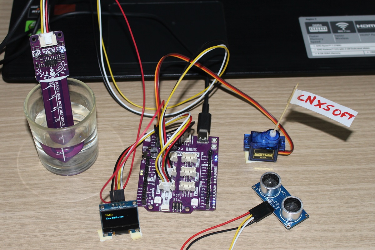
Today, We will review the Cytron Maker Uno RP2040 development board combining the Arduino UNO form factor with the Raspberry Pi RP2040 microcontroller that makes it programmable with the Arduino IDE (C/C++), Micropython, or CircuitPython.
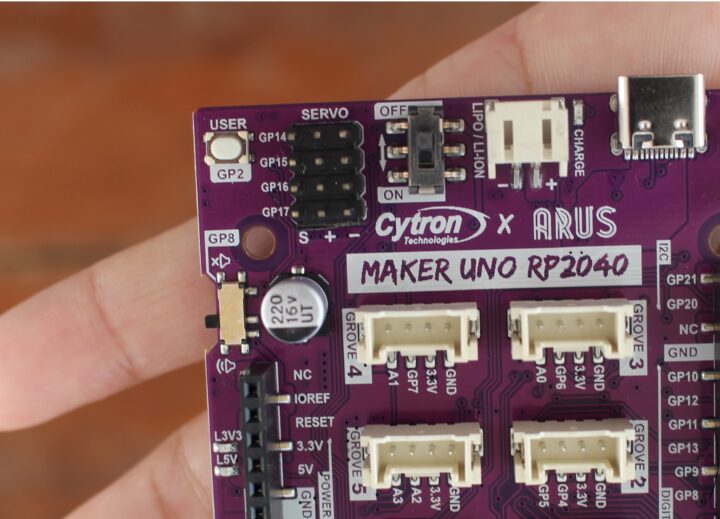
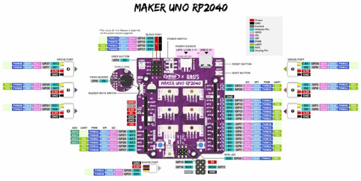
The board is suitable for both beginners and advanced users with a convenient port layout that includes a “Maker” connector plus six Grove connectors for sensor modules and a header for four servos besides the Arduino UNO headers. The board offers two power options: USB (5V) via the USB-C connector or a single-cell LiPo/Li-Ion battery via the LiPo connector.
Cytron Maker Uno RP2040 specifications
- SoC – Raspberry Pi RP2040 dual-core Arm Cortex-M0+ processor @ up to 133 MHz with 264 KB SRAM
- Storage – 2MB flash
- USB – USB-C port for power and programming
- Expansion
- Arduino UNO headers for shields
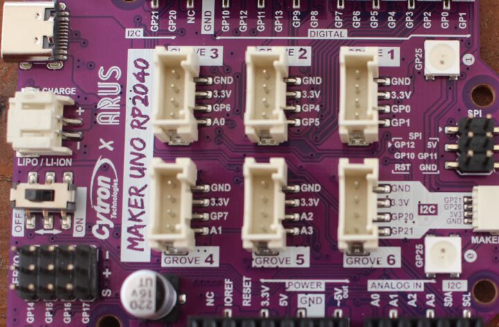
- 6x Grove Ports (Digital I/O, PWM Output, UART, I2C, Analog Input)
- 1x Maker port compatible with Qwiic, STEMMA/QT, and Grove module (the latter via conversion cable)
- 12-pin header for 4x servos
- Misc
- 16x Status LEDs for GPIO
- 1x Piezo Buzzer with mute switch
- User programmable keypad
- Reset button
- Boot button
- 2x RGB LEDs (WS2812)
- Power Supply
- 5V via USB-C port
- Single-cell LiPo connector with built-in overcharge/discharge protection circuitry
- Dimensions – 60.96 x 9.40 cm (Arduino UNO form factor)
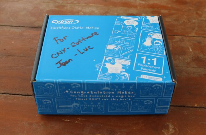
Unboxing of the Cytron Maker Uno RP2040 kit
The Maker Uno RP2040 can be purchased as a standalone board, but we requested a few modules to make the review more interesting and received everything in a single package.
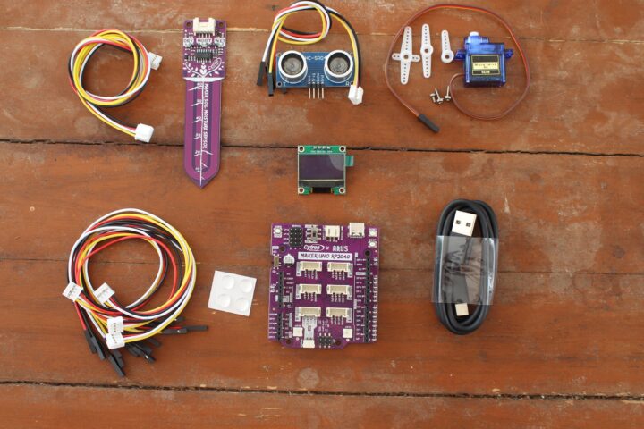
Our kit includes the Maker Uno RP2040 itself, four Grove to jumper cables, a USB-A to USB-C cable, a soil moisture sensor with one Grove cable, an HC-SR04 ultrasonic sensor with a Grove cable, a SG90 micro servo with accessories, a 0.96-inch I2C OLED display (128×64 resolution), and four silicon rubber feet.
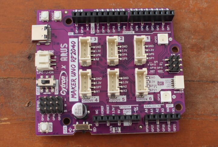
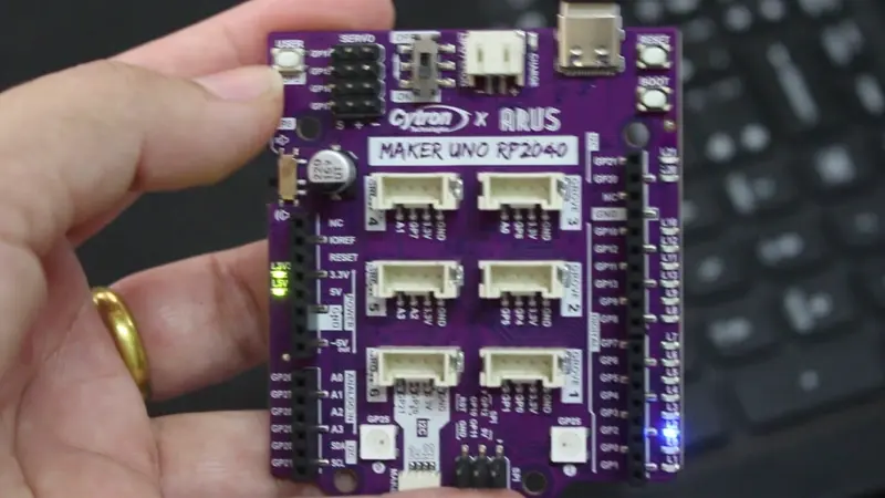
Here’s a closer look at the top of the board…
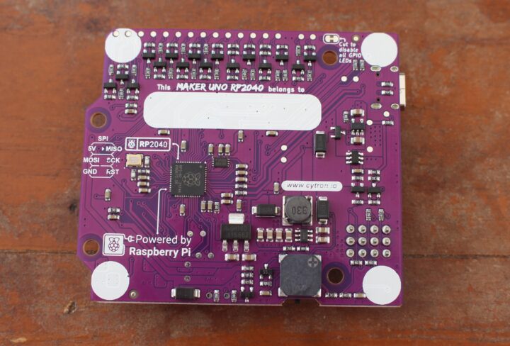
… and the bottom side with the Raspberry Pi RP2040 microcontroller and a white area to let students write their names.
All modules are well-known off-the-shelf parts so we won’t go into details this time.
Getting started with the Maker Uno RP2040 board using the Arduino IDE
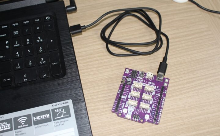
As mentioned in the introduction, the Maker Uno RP2040 can be powered with either a USB Type-C cable (5V) or a single-cell Li-Po/Li-Ion battery (3.7V). In this review, we will use a USB Type-C cable for power and to program the board with a laptop running Windows 11.
The Maker Uno RP2040 supports Arduino, Micropython, and CircuitPython programming, but in this review, we will be focusing on the former. So the first step is to download and install the Arduino IDE for your operating system. We used the latest version available at the time of the review, namely Arduino IDE 2.3.2 for Windows.
Arduino IDE configuration
We’ll be mostly following Cytron’s tutorial to work with the Cytron Maker UNO RP2040 using the Arduino IDE. Three steps are needed for the initial configuration.
- Add Maker Uno RP2040 to the Arduino IDE.
-
- Go to File->Preferences menu, and add the URL “https://github.com/earlephilhower/arduino-pico/releases/download/global/package_rp2040_index.json” in the “Additional Boards Manager URLs”
- Select OK and search for “Uno RP2040” to install the board package.
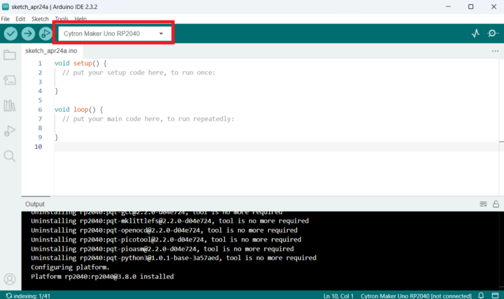
- Once installed, you will find the Maker Uno RP2040 board in the Arduino IDE. Just select it from Tools > Board > Raspberry Pi Pico/RP2040 > Cytron Maker Uno RP2040 or in the drop-down menu.
-
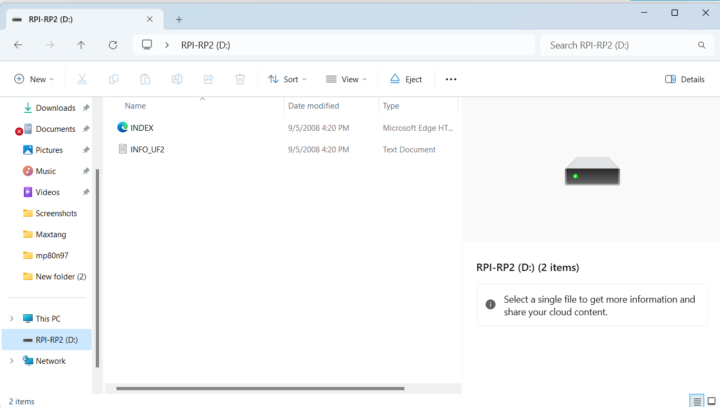
- Enter Bootloader mode by connecting the Maker Uno RP2040 to your laptop. Press and hold the BOOT button and press RESET (just one press!) and a new drive named RPI-RP2 will appear in the File Manager.
- Select the board and COM port
- Select the Maker Uno RP2040 board from Tools > Board > Raspberry Pi Pico/RP2040 > Cytron Maker Uno RP2040
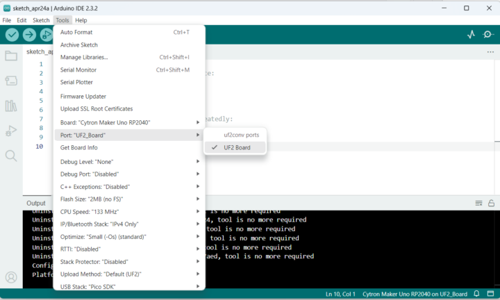
- Select the COM port by going to Tools > Port (the first time the COM port will be “UF2_Board”). After uploading the sketch, the board will reset and the COM port will appear under a name such as “COM12”. Now we are ready to start coding.
Blinking some LEDs
Make sure the correct board and COM port are selected in the Arduino and copy the following code to blink two LEDs every 500ms:
/*
DESCRIPTION:
This example code will use Maker Uno RP2040 to light up any of two onboard GPIOs LEDs alternately.
For this code, GPIOs LED for GPO and GP1 pin are selected.
Each LED will be blinking every each 0.5 second alternately.

AUTHOR   : Cytron Technologies Sdn Bhd
WEBSITE  : www.cytron.io
EMAIL    : [email protected]
*/

 // Pin assignments for LEDs
const int ledPin1 = 0;
const int ledPin2 = 1;

void setup() {
  // initialize leds on GP0 and GP1 pins as output.
  pinMode(ledPin1, OUTPUT);
  pinMode(ledPin2, OUTPUT);
}

void loop() {
  // led GP0 is light up for 0.5s then turned off.
  digitalWrite(ledPin1, HIGH);
  delay(500);
  digitalWrite(ledPin1, LOW);
  delay(500);

  // led GP1 is light up for 0.5s then turned off.
  digitalWrite(ledPin2, HIGH);
  delay(500);
  digitalWrite(ledPin2, LOW);
  delay(500);
}
Select Verify to check the code compiles and then Upload the sketch to your Maker Uno RP2040 board.
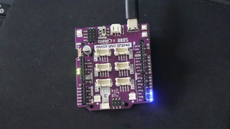
Two LEDs should now be blinking on the board (connected to GP0 and GP1) alternating every 0.5 seconds. (Note GP2 is always on, and we can’t see GP1 clearly in the animated WebP file above but it’s blinking too).
Controlling the RGB LEDs
Here’s an Arduino sketch to cycle the colors of the two RGB LEDs on the board going to Red, Green, Blue, and off:
/*
DESCRIPTION:
This example code will use Maker Uno RP2040 to light up the on-board RGB leds.
The RGB LEDs will sequentially changing their colors individually.

AUTHOR   : Cytron Technologies Sdn Bhd
WEBSITE  : www.cytron.io
EMAIL    : [email protected]

REFERENCE:
Adafruit_NeoPixel library link:
https://github.com/adafruit/Adafruit_NeoPixel/tree/master

*/

#include <Adafruit_NeoPixel.h>

// Declare pin number of the Neopixel LED and the number of the LED
const int neoPin = 25;
const int numPixels = 2;

// Initialize the NeoPixel RGB LEDs on pin GP25
Adafruit_NeoPixel pixels(numPixels, neoPin, NEO_GRB + NEO_KHZ800);

void setup() {

  pixels.begin(); // Initialize NeoPixel library
  pixels.clear(); // Set all pixel colors to 'off'
  pixels.show();  // Send the updated pixel colors to the hardware.
}

void loop() {

  // pixels.Color() takes RGB values, from 0,0,0 up to 255,255,255
  // NeoPixels are numbered from 0 to (number of pixels - 1).

  pixels.setPixelColor(0, pixels.Color(200, 0, 0)); // Red
  pixels.setPixelColor(1, pixels.Color(200, 0, 200)); // Magenta
  pixels.show();   // Send the updated pixel colors to the hardware.
  delay(1000);

  pixels.setPixelColor(0, pixels.Color(0, 200, 0)); // Green
  pixels.setPixelColor(1, pixels.Color(200, 200, 0)); // Yellow
  pixels.show();   // Send the updated pixel colors to the hardware.
  delay(1000);

  pixels.setPixelColor(0, pixels.Color(0, 0, 200)); // Blue
  pixels.setPixelColor(1, pixels.Color(0, 200, 200)); // Cyan
  pixels.show();   // Send the updated pixel colors to the hardware.
  delay(1000);

  pixels.setPixelColor(0, pixels.Color(0, 0, 0)); // Black (turn off the LED)
  pixels.setPixelColor(1, pixels.Color(0, 0, 0)); // Black (turn off the LED)
  pixels.show();   // Send the updated pixel colors to the hardware.
  delay(1000);
}
Let’s now Upload the sketch to the maker Uno RP2040 board…
The RGB LEDs will change color and turn off in a loop as expected.
Controlling an LED with the user button
The Arduino sketch below turns on or off the LED connected to the GP1 pin when pressing the user button (GP2) on the Maker Uno RP2040 board:
/*
DESCRIPTION:
This example code will show how to use the User button on the Maker Uno RP2040 as an Input.
In this code, the button will be used to control an on-board LED.
If the button is pressed, the LED will light up for 0.5 second then turned off

AUTHOR  : Cytron Technologies Sdn Bhd
WEBSITE  : www.cytron.io
EMAIL    : [email protected]
*/

  // Declare pin assignments for LED and button.
const int ledPin1 = 8;
const int btn1 = 2;


void setup() {
  // initialize leds GP8 pins as output and the user button GP2 as input
  pinMode(ledPin1, OUTPUT);
  pinMode(btn1, INPUT_PULLUP);

}

void loop() {
  // check button 1 (GP2) is pressed
  if (!digitalRead(btn1)) {
    // led GP0 is light up for 0.5s then turned off.
    digitalWrite(ledPin1, HIGH);
    delay(500);
    digitalWrite(ledPin1, LOW);
  }

}
Buzzer testing
We’ll play some sound through the buzzer when pressing the user button (GP2) using this code:
/*
DESCRIPTION:
This example code will use the the buzzzer on the Maker Uno RP2040 to play the tones.
The User button also used in this code. Upon startup, a short melody will be played
and then the code will wait for the button press to play another set of short tones.

AUTHOR   : Cytron Technologies Sdn Bhd
WEBSITE  : www.cytron.io
EMAIL    : [email protected]
*/

// Declare pin assigment for buzzer and button
const int buzzerPin = 8;
const int btn1 = 2;

// Create an array of the melody note frequency with its corresponding duration for each note
int melody_note[10] = {659, 659, 0, 659, 0, 523, 659, 0, 784, 0}; // [E5, E5, REST, E5, REST, C5, E5, REST, G5]
int melody_duration[10] = {150, 150, 150, 150, 150, 150, 150, 150, 200, 150};

void setup(){
  // Initialize buzzer pin as output
  pinMode(buzzerPin, OUTPUT);

  // Initialize buttons
  pinMode(btn1, INPUT_PULLUP);

  // Play melody during start up
  play_melody(buzzerPin);
}

void loop(){
  // Check button 1 (GP2) is pressed
  if (!digitalRead(btn1)) {
    // Play tones
    tone(buzzerPin,262,100);
    delay(100);
    tone(buzzerPin,659,100);
    delay(100);
    tone(buzzerPin,784,100);
    delay(100);
    noTone(buzzerPin);
  }
}

void play_melody(int pin){
  for(int i=0; i<10; i++){
    if(melody_note[i] == 0){
      noTone(pin);
    }
    else{
     tone(pin, melody_note[i], 100);
    }
    delay(int(melody_duration[i]));
  }
}
After uploading the sketch, we should hear a short snippet of Mario Bros theme melody each time we press the user button
Arduino sketch to control a micro servo from the Maker Uno RP2040
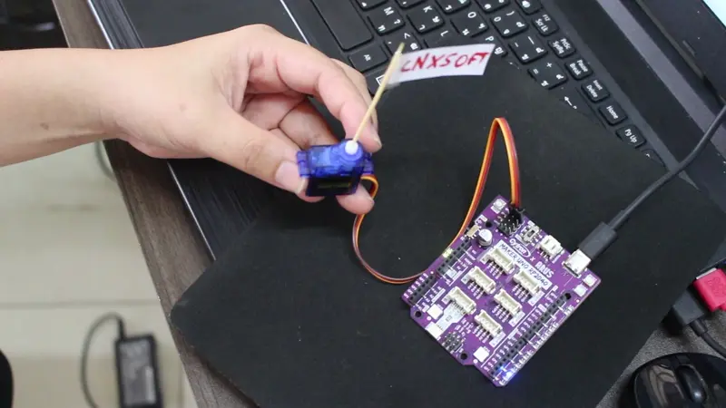
We’ve only tested hardware built-in on the Maker Uno RP2040 board so far, but we’ll now start testing expansion capabilities by connecting an S90 micro servo to the GP14, +, and – pins of the SERVO header.
The Arduino sketch below will rotate the four servos from 0 degrees to 180 degrees and back in an infinite loop:
/*
DESCRIPTION:
This example code will use Maker UNO RP2040 to control four servo motors connected to the onboard servo ports.
The servo motor will sweep from 0° to 180° with an increment of 1° every 10 milliseconds.
Then  the servos moves back from 180 degrees to 0 degrees with a decrement of 1 degree every each 10 milliseconds.

AUTHOR   : Cytron Technologies Sdn Bhd
WEBSITE  : www.cytron.io
EMAIL    : [email protected]
*/

  // Include the servo library
#include <Servo.h>

  // Create servo objects for each servos
Servo servo1;
Servo servo2;
Servo servo3;
Servo servo4;

void setup() {

  // Attach each servo object to their corresponding pins
  servo1.attach(14);
  servo2.attach(15);
  servo3.attach(16);
  servo4.attach(17);
}

void loop() {

   // Move the servos from 0 degress to 180 degrees with with an increment of 1 degree per step
  for (int pos = 0; pos <= 180; pos += 1) {
  servo1.write(pos);     // Set Servo 1 position to 'pos' degrees
  servo2.write(pos);     // Set Servo 2 position to 'pos' degrees
  servo3.write(pos);     // Set Servo 3 position to 'pos' degrees
  servo4.write(pos);     // Set Servo 4 position to 'pos' degrees
  delay(10);  // Pause for 15 milliseconds to control the speed of servo movement
  }

   // Move the servos from 180 degress to 0 degrees with with a decrement of 1 degree per step
  for (int pos = 200; pos >= 0; pos -= 1) {
  servo1.write(pos);     // Set Servo 1 position to 'pos' degrees
  servo2.write(pos);     // Set Servo 2 position to 'pos' degrees
  servo3.write(pos);     // Set Servo 3 position to 'pos' degrees
  servo4.write(pos);     // Set Servo 4 position to 'pos' degrees
  delay(10);   // Pause for 15 milliseconds to control the speed of servo movement
  }
}

/*
NOTE:
This code is written for standard servo motors. If you are using  360 degree continous rotation servo,
the servo.write (pos) function behave differently than standard servo. It controls speed rather than position.
A value near 90 means no movement, 0 is full speed in one direction and  180 is full speed in other direction

*/
We only have one micro servo which we connected to GP14 (S1) and added a small flag for dramatic effect 
The servo motor rotates smoothly from 0° to 180° in increments of 1° every 10 ms. When it reaches 180°, it reverses direction and moves back to 0° in increments of 1° every 10 ms.
Reading analog values from a soil moisture sensor
The Maker Uno RP2040 board comes with various Grove connectors with digital, analog, or I2C interfaces.
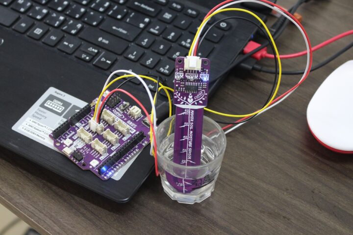
We’ll first test an analog connector (Grove 5) using a Maker soil moisture sensor to measure humidity in a glass of water.
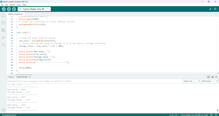
There are dry, moist, and wet LEDS on the sensor module, but the following code will report the raw and voltage values from the A3 (GP29) pin in the serial monitor:
/*
DESCRIPTION:
This example code will use Maker Uno RP2040 to read the analog input from Maker Soil Module
and then show the result on serial monitor. This code also applicable to any analog sensor.

CONNECTION:

Grove 5 of Maker Uno RP2040 : Maker Soil Module
GP29 - OUT pin of the Maker Soil Module

AUTHOR   : Cytron Technologies Sdn Bhd
WEBSITE  : www.cytron.io
EMAIL    : [email protected]
*/

int sensorPin = 29;    // select the input pin for the potentiometer
int raw_value = 0;
float voltage_value = 0;

void setup() {
  // declare the sensorPin as an OUTPUT:
  pinMode(sensorPin, INPUT);
  Serial.begin(9600);
  // enable adc resolution to 12-bit (default 10-bit)
  analogReadResolution(12);
}

void loop() {

  // read the value from the sensor:
  raw_value = analogRead(sensorPin);
  // Convert the raw ADC value to voltage (3.3V is the board's voltage reference)
  voltage_value = (raw_value * 3.3) / 4095;

  Serial.print("Raw Value : ");
  Serial.println(raw_value);
  Serial.print("Voltage Value : ");
  Serial.println(voltage_value);
  Serial.println("---------------------------");

  delay(1000);
}
Once the sketch is running, we can open the Serial Monitor to check out the values updates in a loop every 1 seconds.
Reading digital values from an HC-SR04 ultrasonic sensor
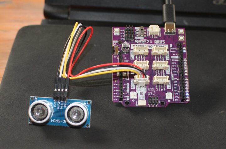
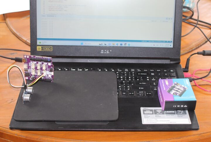
While only two of the Grove connectors support analog, any of the 6 Grove connectors and the Maker port can be configured to take a digital sensor. In this review, we will be using an HC-SR04 ultrasonic sensor module connected to pins 20 (ECHO signal), 21 (TRIG signal), and 3.3V and GND of the Grove 6 connector on the Maker Uno RP2040 board in order to measure the distance to the Cytron retail box.
Here’s the Arduino sketch to measure the distance and output the value in the serial monitor:
/*
DESCRIPTION:
This example code will use Maker UNO RP2040 with Ultrasonic Sensor HC-SR04P
to measure distance and then display the readings on serial monitor.

CONNECTION:

HC-SR04P - Grove 6 of Maker UNO RP2040
           or
GP20 - Echo pin of HC-SR04P
GP21 - Trig pin of HC-SR04P

AUTHOR   : Cytron Technologies Sdn Bhd
WEBSITE  : www.cytron.io
EMAIL    : [email protected]

REFERENCE:
Code adapted from www.HowToMechatronics.com:
https://howtomechatronics.com/tutorials/arduino/ultrasonic-sensor-hc-sr04/

*/

// defines pins numbers
const int echoPin = 20;
const int trigPin = 21;

// defines variables
long duration;
int distance;

void setup() {
  pinMode(trigPin, OUTPUT); // Sets the trigPin as an Output
  pinMode(echoPin, INPUT); // Sets the echoPin as an Input
  Serial.begin(9600); // Starts the serial communication
}
void loop() {
  // Clears the trigPin
  digitalWrite(trigPin, LOW);
  delayMicroseconds(2);

  // Sets the trigPin on HIGH state for 10 micro seconds
  digitalWrite(trigPin, HIGH);
  delayMicroseconds(10);
  digitalWrite(trigPin, LOW);

  // Measure the response from the echoPin
  duration = pulseIn(echoPin, HIGH);

  // Calculate the distance from duration value
  // Use 343 metres per second as the speed of sound

  distance = duration * 0.034 / 2;

  // Prints the distance on the Serial Monitor
  Serial.print("Distance : ");
  Serial.print(distance);
  Serial.println(" cm");
  delay(100);
}
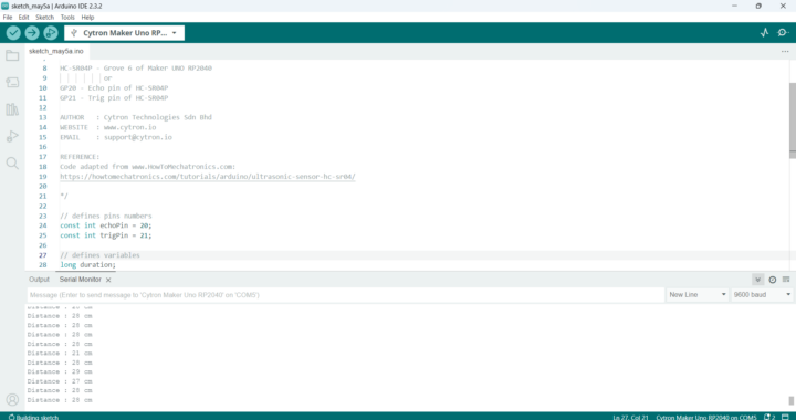
Let’s upload the code to the board and move the box at different distances from the package.
The distance will be shown in the serial monitor in centimeters.
Connecting an I2C OLED module to the Maker Uno RP2040.
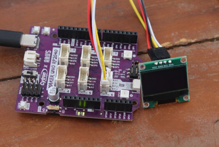
We’ve already tested analog input and digital I/O interface, and we’ll now switch to I2C using the small SSD1315 OLED display provided in our kit connected to the Grove 6 I2C connector.
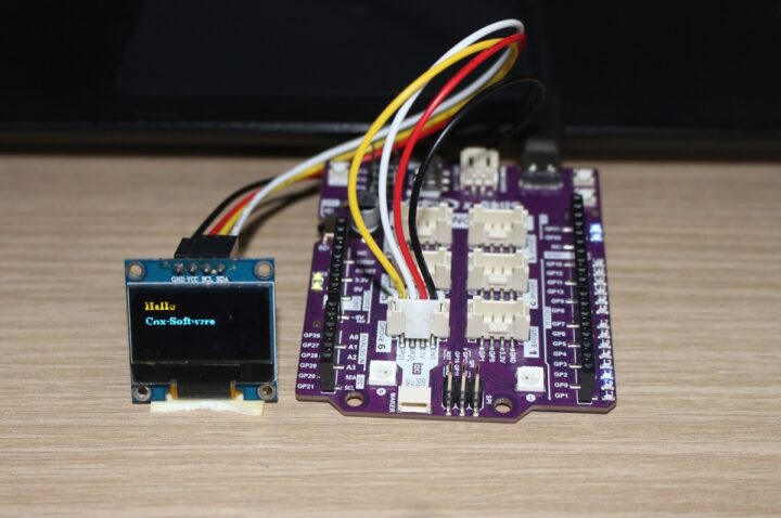
Here’s a simple Arduino sketch to write some messages on the OLED module:
/*
DESCRIPTION:
This example code will demonstrate how to use Maker UNO RP2040 with OLED Display SSD1315 to display text.

CONNECTION:
Grove 6 of Maker UNO RP2040 - OLED Display SSD1315 Grove

GP20 - SDA
GP21 - SCL

AUTHOR   : Cytron Technologies Sdn Bhd
WEBSITE  : www.cytron.io
EMAIL    : [email protected]

REFERENCE:
Code adapted from:
https://wiki.seeedstudio.com/Grove-OLED-Display-0.96-SSD1315/
*/
#include <Arduino.h>
#include <U8g2lib.h>
#ifdef U8X8_HAVE_HW_SPI
#include <SPI.h>
#endif
#ifdef U8X8_HAVE_HW_I2C
#include <Wire.h>
#endif

U8G2_SSD1306_128X64_NONAME_F_SW_I2C u8g2(U8G2_R0, /* clock(SCL)*/ SCL, /*data(SDA)*/ SDA, /* reset=*/ U8X8_PIN_NONE);

void setup(void) {
  u8g2.begin();
}

void loop(void) {
  u8g2.clearBuffer();
  u8g2.setFont(u8g2_font_ncenB08_tr);

  // Adjusted coordinates for better positioning
  u8g2.drawStr(5, 15, "Hello");
  u8g2.drawStr(5, 30, "Cnx-Software");

  u8g2.sendBuffer();
  delay(1000);
}
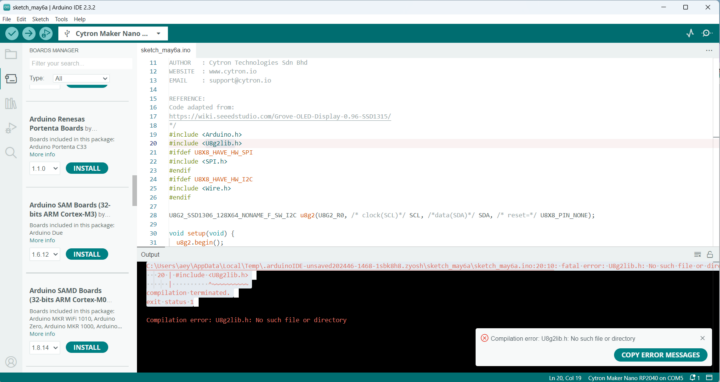
The first time we tried to compile the code it ended up in failure due to u8g2lib.h file missing.
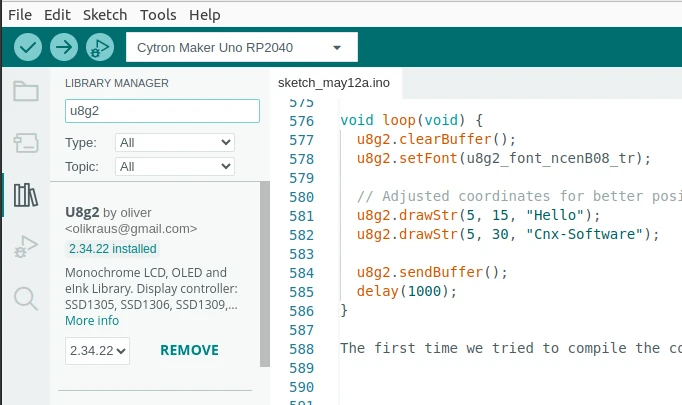
That’s because we’ve yet to install the U8g2 graphics library. It can be installed by going to Tools->Manage Libraries and searching for u8g2.
After loading the code to the board, the display would still stay dark. We eventually tried another similar display OLED module (also 0x7B I2C address) and the text was shown properly.
In this review of the Maker Uno RP2040 board with the Arduino IDE we could blink LEDs, control RGB LED lights, press the user button to turn on one LED or make the buzzer output some melody, control a micro servo, read sensor values from a soil moisture sensor (analog) and an ultrasonic sensor (digital I/O), as well as display text to an I2C OLED module.
All that could be done relatively easily thanks to tutorials by Cytron that are fairly easy to follow even for a beginner. The board is suitable for STEM education with built-in LEDs, RGB LEDs, a buzzer, and expansion capabilities through Arduino headers and Grove and Maker connectors.
We’d like to thank Cytron for sending us the Maker Uno RP2040 kit for review. The Maker Uno RP2040 board can be purchased for $14.90 with some local distributors in Europe, India, Japan, and Egypt. They don’t sell the kit we’ve received directly, but you’ll find the Maker soil moisture sensor, HC-SR04 ultrasonic sensor, SG90 micro Servo, and 0.96-inch I2C OLED display on the company’s online store.
CNXSoft: This review is a translation of the original tutorial on CNX Software Thailand by Suthinee Kerdkaew. Note that Suthinee has limited experience with this type of hardware, having only reviewed the Cytron Maker Nano RP2040 kit with CircuitPython two years ago and no formal IT education. I just gave her the kit and link to Cytron tutorial, and said “Good luck”. I ended up providing some very limited support (maybe 5 to 10 minutes of my time) for some blocking issues, but as a relative beginner, she mostly managed to complete the review on her own.
The post Maker Uno RP2040 review with Arduino IDE using micro servo, soil moisture sensor, ultrasonic sensor, and I2C OLED modules appeared first on CNX Software - Embedded Systems News.

