FreshRSS

Zobrazení pro čtení

Jsou dostupné nové články, klikněte pro obnovení stránky.

GEEKOM A8 Review – Part 3: Ubuntu 24.04 tested on an AMD Ryzen 8945HS mini PC

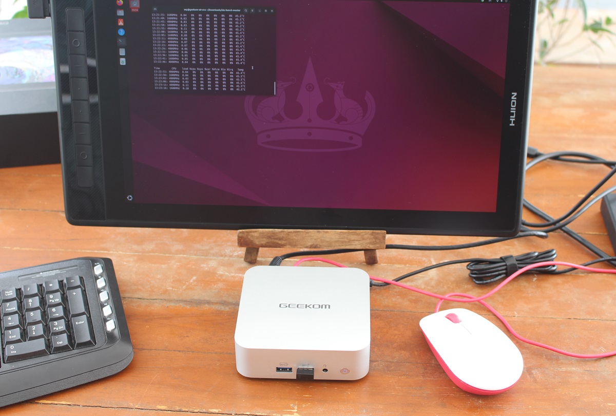
GEEKOM A8 mini PC Review Ubuntu 24.04 Linux

We’ve already checked out GEEKOM A8 mini PC hardware with an unboxing and a teardown, before testing the AMD Ryzen 9 8945HS mini PC in Windows 11 Pro, and we’ll now report our experience with the GEEKOM A8 running Ubuntu 24.04 to see how it performs in Linux.

We tested most features of the GEEKOM A8 mini PC on Ubuntu 24.04, ran several benchmarks to compare it to the similar GEEKOM A7 mini PC, performed storage and networking performance testing, ran stress test to check thermal performance, and measured fan noise and power consumption under various conditions.

GEEKOM A8 mini PC Review Ubuntu 24.04 Linux

Installing Ubuntu 24.04 on the GEEKOM A8 mini PC

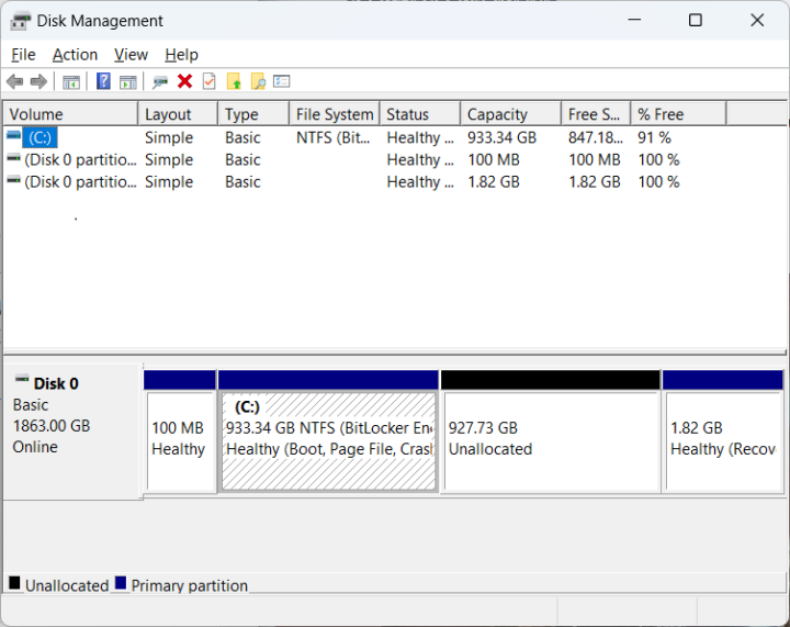
As usual, we resized the Windows 11 partition to install Ubuntu 24.04 alongside Microsoft OS using a bootable USB flash drive created with the Ubuntu ISO.

GEEKOM A8 Disk Management partition

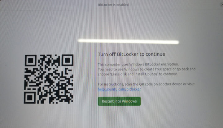
But you’ll notice BitLocker is enabled so the Ubuntu 24.04 installation can’t proceed. The installation wizard will ask us to turn off BitLocker for a dual boot system or to wipe out the Windows installation to install Ubuntu only.

Ubuntu Turn off BitLocker disk encryption

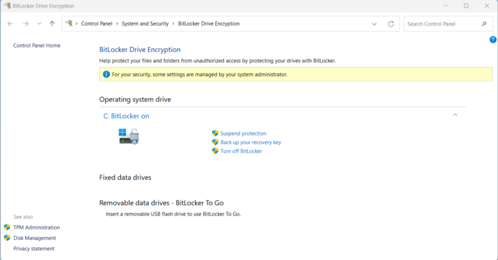
We went back to Windows to disable BitLocker drive encryption as shown in the screenshot below.

Windows 11 BitLocker Drive Encryption

After this change, the Ubuntu 24.04 installation went smoothly on the GEEKOM A8 mini PC, and we didn’t need to enter the BIOS to change the boot priority as we sometimes had to do in the past. You’ll be presented with the Grub menu at boot to select Ubuntu or Windows.

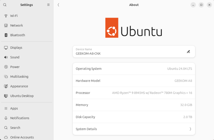
Ubuntu 24.04 system information

The Settings -> About window confirms we have a GEEKOM A8 running Ubuntu 24.04 LTS on a 16-core AMD Ryzen 9 8945HS processor with AMD Radeon 780M graphics, 32GB of RAM 32GB and 2TB of storage.

GEEKOM A8 ubuntu 24.04 system info

We can get a free more details from the command line…

aey@geekom-a8-cnx:~$ cat /etc/lsb-release
DISTRIB_ID=Ubuntu
DISTRIB_RELEASE=24.04
DISTRIB_CODENAME=noble
DISTRIB_DESCRIPTION="Ubuntu 24.04 LTS"
aey@geekom-a8-cnx:~$ uname -a
Linux A8 6.8.0-35-generic #35-Ubuntu SMP PREEMPT_DYNAMIC Mon May 20 15:51:52 UTC 2024 x86_64 x86_64 x86_64 GNU/Linux
aey@geekom-a8-cnx:~$ free -mh
               total        used        free      shared  buff/cache   available
Mem:            30Gi       2.8Gi        27Gi        91Mi       1.1Gi        27Gi
Swap:          8.0Gi          0B       8.0Gi

and even more with inxi utility:

aey@geekom-a8-cnx:~$ inxi -Fc0
System:
  Host: A8 Kernel: 6.8.0-35-generic arch: x86_64 bits: 64
  Desktop: GNOME v: 46.0 Distro: Ubuntu 24.04 LTS (Noble Numbat)
Machine:
  Type: Desktop System: GEEKOM product: A8 v: N/A serial: <superuser required>
  Mobo: N/A model: A8 serial: <superuser required> UEFI: American
    Megatrends LLC. v: 0.45 date: 04/07/2024
CPU:
  Info: 8-core model: AMD Ryzen 9 8945HS w/ Radeon 780M Graphics bits: 64
    type: MT MCP cache: L2: 8 MiB
  Speed (MHz): avg: 3479 min/max: 1600/6844 cores: 1: 4000 2: 1618 3: 4000
    4: 4000 5: 4000 6: 4000 7: 4000 8: 4000 9: 1397 10: 4000 11: 4000 12: 4000
    13: 662 14: 4000 15: 4000 16: 4000
Graphics:
  Device-1: AMD Phoenix3 driver: amdgpu v: kernel
  Display: wayland server: X.Org v: 23.2.6 with: Xwayland v: 23.2.6
    compositor: gnome-shell driver: dri: radeonsi gpu: amdgpu
    resolution: 1920x1080~60Hz
  API: EGL v: 1.5 drivers: radeonsi,swrast
    platforms: wayland,x11,surfaceless,device
  API: OpenGL v: 4.6 compat-v: 4.5 vendor: amd mesa v: 24.0.5-1ubuntu1
    renderer: AMD Radeon Graphics (radeonsi gfx1103_r1 LLVM 17.0.6 DRM 3.57
    6.8.0-35-generic)
Audio:
  Device-1: AMD Rembrandt Radeon High Definition Audio driver: snd_hda_intel
  Device-2: AMD Family 17h/19h HD Audio driver: snd_hda_intel
  API: ALSA v: k6.8.0-35-generic status: kernel-api
  Server-1: PipeWire v: 1.0.5 status: active
Network:
  Device-1: Realtek RTL8125 2.5GbE driver: r8169
  IF: enp1s0 state: down mac: 38:f7:cd:c8:2e:72
  Device-2: MEDIATEK MT7922 802.11ax PCI Express Wireless Network Adapter
    driver: mt7921e
  IF: wlp2s0 state: up mac: 94:bb:43:1a:52:92
Bluetooth:
  Device-1: IMC Networks Wireless_Device driver: btusb type: USB
  Report: hciconfig ID: hci0 rfk-id: 0 state: down
    bt-service: enabled,running rfk-block: hardware: no software: no
    address: 00:00:00:00:00:00
Drives:
  Local Storage: total: 1.82 TiB used: 14.83 GiB (0.8%)
  ID-1: /dev/nvme0n1 vendor: Acer model: SSD N7000 2TB size: 1.82 TiB
Partition:
  ID-1: / size: 912.1 GiB used: 14.75 GiB (1.6%) fs: ext4 dev: /dev/nvme0n1p5
  ID-2: /boot/efi size: 96 MiB used: 78.3 MiB (81.6%) fs: vfat
    dev: /dev/nvme0n1p1
Swap:
  ID-1: swap-1 type: file size: 8 GiB used: 0 KiB (0.0%) file: /swap.img
Sensors:
  System Temperatures: cpu: 53.6 C mobo: 52.0 C gpu: amdgpu temp: 48.0 C
  Fan Speeds (rpm): N/A
Info:
  Memory: total: 32 GiB note: est. available: 30.63 GiB used: 2.82 GiB (9.2%)
  Processes: 358 Uptime: 2h 21m Shell: Bash inxi: 3.3.34

The program lists the AMD Ryzen 9 8945HS processor with 8 cores and 16 threads as expected but Linux reports a maximum speed of 6,844 MHz… against the advertised 5.2 GHz Turbo frequency. Some peripherals include the Realtek RTL8125 2.5GbE controller and MediaTek MT7922 WiFi 6 network adapter. Bluetooth is detected but with a MAC address of 00:00:00:00:00:00, and as we’ll see further below it does not work. The idle CPU temperature is reported to be 53.6°C, but we will check that again.

GEEKOM A8 benchmarks on Ubuntu 24.04

We’ll start benchmarking the AMD Ryzen 9 8945HS mini PC with Thomas Kaiser’s sbc-bench.sh:

aey@geekom-a8-cnx:~/Downloads/sbc-bench-master$ sudo ./sbc-bench.sh -r
Starting to examine hardware/software for review purposes...

sbc-bench v0.9.67

Installing needed tools: apt-get -f -qq -y install gcc make build-essential lm-sensors powercap-utils curl git links mmc-utils smartmontools stress-ng, p7zip 16.02, tinymembench, ramlat, mhz, cpufetch, cpuminer. Done.
Checking cpufreq OPP. Done.
Executing tinymembench. Done.
Executing RAM latency tester. Done.
Executing OpenSSL benchmark. Done.
Executing 7-zip benchmark. Done.
Throttling test: heating up the device, 5 more minutes to wait. Done.
Checking cpufreq OPP again. Done (10 minutes elapsed).

Results validation:

  * Measured clockspeed not lower than advertised max CPU clockspeed
  * No swapping
  * Background activity (%system) OK
  * No throttling

Full results uploaded to https://0x0.st/XboB.bin

# GEEKOM A8  / Ryzen 9 8945HS w/ Radeon 780M Graphics

Tested with sbc-bench v0.9.67 on Thu, 06 Jun 2024 18:45:34 +0700. Full info: [https://0x0.st/XboB.bin](http://0x0.st/XboB.bin)

### General information:

    Information courtesy of cpufetch:
    
    Name:                AMD Ryzen 9 8945HS w/ Radeon 780M Graphics
    Microarchitecture:   Zen 4
    Technology:          4nm
    Max Frequency:       6.843 GHz
    Cores:               8 cores (16 threads)
    AVX:                 AVX,AVX2,AVX512
    FMA:                 FMA3
    L1i Size:            32KB (256KB Total)
    L1d Size:            32KB (256KB Total)
    L2 Size:             1MB (8MB Total)
    L3 Size:             16MB
    
    Ryzen 9 8945HS w/ Radeon 780M Graphics, Kernel: x86_64, Userland: amd64
    
    CPU sysfs topology (clusters, cpufreq members, clockspeeds)
                     cpufreq   min    max
     CPU    cluster  policy   speed  speed   core type
      0        0        0     1600    6844       -
      1        0        1     1600    6844       -
      2        0        2     1600    6844       -
      3        0        3     1600    6844       -
      4        0        4     1600    6844       -
      5        0        5     1600    6844       -
      6        0        6     1600    6844       -
      7        0        7     1600    6844       -
      8        0        8     1600    6844       -
      9        0        9     1600    6844       -
     10        0       10     1600    6844       -
     11        0       11     1600    6844       -
     12        0       12     1600    6844       -
     13        0       13     1600    6844       -
     14        0       14     1600    6844       -
     15        0       15     1600    6844       -

31362 KB available RAM

### Policies (performance vs. idle consumption):

Status of performance related policies found below /sys:

    /sys/module/pcie_aspm/parameters/policy: default [performance] powersave powersupersave

### Clockspeeds (idle vs. heated up):

Before at 54.2°C:

    cpu0: 

After at 92.0°C:

    cpu0: OPP: 6843, Measured: 4985     (-27.2%)

### Performance baseline

  * memcpy: 20318.5 MB/s, memchr: 78557.7 MB/s, memset: 62156.7 MB/s
  * 16M latency: 28.89 20.10 29.21 20.17 27.64 30.71 36.28 41.94 
  * 128M latency: 99.04 98.41 99.25 98.73 98.85 99.52 104.9 108.8 
  * 7-zip MIPS (3 consecutive runs): 69297, 68708, 68364 (68790 avg), single-threaded: 6446
  * `aes-256-cbc    1160880.19k  1344417.81k  1390608.64k  1405969.41k  1418925.40k  1397435.05k`
  * `aes-256-cbc    1177681.15k  1359618.26k  1404829.44k  1417271.98k  1420967.94k  1422136.66k`

### PCIe and storage devices:

  * Realtek RTL8125 2.5GbE: Speed 5GT/s, Width x1, driver in use: r8169, 
  * MEDIATEK MT7922 802.11ax PCI Express Wireless Network Adapter: Speed 5GT/s, Width x1, driver in use: mt7921e, 
  * O2 SD/MMC Card Reader: Speed 2.5GT/s, Width x1, driver in use: sdhci-pci, 
  * AMD Device 15b9: Speed 16GT/s, Width x16, driver in use: xhci_hcd, ASPM Disabled
  * AMD Device 15ba: Speed 16GT/s, Width x16, driver in use: xhci_hcd, ASPM Disabled
  * AMD Device 15c0: Speed 16GT/s, Width x16, driver in use: xhci_hcd, ASPM Disabled
  * AMD Device 15c1: Speed 16GT/s, Width x16, driver in use: xhci_hcd, ASPM Disabled
  * AMD Pink Sardine USB4/Thunderbolt NHI controller #1: Speed 16GT/s, Width x16, driver in use: thunderbolt, ASPM Disabled
  * 1.8TB "Acer SSD N7000 2TB" SSD as /dev/nvme0: Speed 16GT/s, Width x4, 0% worn out, drive temp: 45°C, ASPM Disabled

### Challenging filesystems:

The following partitions are NTFS: nvme0n1p3,nvme0n1p4 -> https://tinyurl.com/mv7wvzct

### Swap configuration:

  * /swap.img on /dev/nvme0n1p5: 8.0G (0K used)

### Software versions:

  * Ubuntu 24.04 LTS (noble)
  * Compiler: /usr/bin/gcc (Ubuntu 13.2.0-23ubuntu4) 13.2.0 / x86_64-linux-gnu
  * OpenSSL 3.0.13, built on 30 Jan 2024 (Library: OpenSSL 3.0.13 30 Jan 2024)    

### Kernel info:

  * `/proc/cmdline: BOOT_IMAGE=/boot/vmlinuz-6.8.0-35-generic root=UUID=e2b1df18-cd94-43ee-8c4c-db149064cda7 ro quiet splash vt.handoff=7`
  * Vulnerability Spec rstack overflow:   Mitigation; Safe RET
  * Vulnerability Spec store bypass:      Mitigation; Speculative Store Bypass disabled via prctl
  * Vulnerability Spectre v1:             Mitigation; usercopy/swapgs barriers and __user pointer sanitization
  * Kernel 6.8.0-35-generic / CONFIG_HZ=1000

Waiting for the device to cool down...................................... 49.6°C

The script did not detect any CPU throttling, but the 7-zip benchmark slowly decreases between each run (69,297 points -> 68,708 points -> 68,364 points) pointing to some sort of thermal or power throttling.

Let’s check the power  limits with RyzenAdj (Note: we had to disable secure boot for this to work):

aey@geekom-a8-cnx:~/Downloads/RyzenAdj-master/build$ sudo ./ryzenadj -i
CPU Family: Hawk Point
SMU BIOS Interface Version: 14
Version: v0.15.0 
PM Table Version: 4c0008
|        Name         |   Value   |     Parameter      |
|---------------------|-----------|--------------------|
| STAPM LIMIT         |    45.000 | stapm-limit        |
| STAPM VALUE         |     1.716 |                    |
| PPT LIMIT FAST      |    65.000 | fast-limit         |
| PPT VALUE FAST      |     6.726 |                    |
| PPT LIMIT SLOW      |    54.000 | slow-limit         |
| PPT VALUE SLOW      |     2.968 |                    |
| StapmTimeConst      |   100.000 | stapm-time         |
| SlowPPTTimeConst    |   100.000 | slow-time          |
| PPT LIMIT APU       |    54.000 | apu-slow-limit     |
| PPT VALUE APU       |       nan |                    |
| TDC LIMIT VDD       |    55.001 | vrm-current        |
| TDC VALUE VDD       |     1.489 |                    |
| TDC LIMIT SOC       |    15.001 | vrmsoc-current     |
| TDC VALUE SOC       |     1.360 |                    |
| EDC LIMIT VDD       |   130.001 | vrmmax-current     |
| EDC VALUE VDD       |    55.895 |                    |
| EDC LIMIT SOC       |    20.001 | vrmsocmax-current  |
| EDC VALUE SOC       |     3.375 |                    |
| THM LIMIT CORE      |    92.001 | tctl-temp          |
| THM VALUE CORE      |    45.931 |                    |
| STT LIMIT APU       |     0.000 | apu-skin-temp      |
| STT VALUE APU       |     0.000 |                    |
| STT LIMIT dGPU      |     0.000 | dgpu-skin-temp     |
| STT VALUE dGPU      |     0.000 |                    |
| CCLK Boost SETPOINT |       nan | power-saving /     |
| CCLK BUSY VALUE     |       nan | max-performance    |

The power limits are as follows:

  • Sustained Power Limit (STAPM LIMIT) – 45 Watts
  • Actual Power Limit (PPT LIMIT FAST) – 65 Watts
  • Average Power Limit (PPT LIMIT SLOW) – 54 Watts

For reference, the AMD Ryzen 9 8945HS CPU has a configurable TDP between 35 and 54W.

We’ll now test the single-core and multi-core CPU performance with Geekbench 6.3.0.

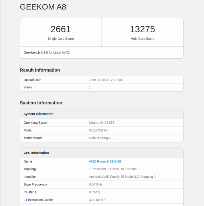
Geekbench 6.3.0 linux GEEKOM A8

The GEEKOM A8 achieved 2,661 points for the single-core test and 13,275 points for the multi-core test.

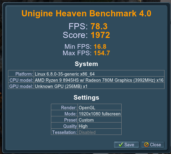
We’ll start testing the GPU with Unigine Heaven Benchmark 4.0. The system could render the benchmark at 78.3 FPS on average with a score of 1,972 points at the standard 1920×1080 resolution.

Radeon 780M Unigine Heaven Benchmark 4.0

YouTube 4K and 8K video playback was tested with the Chrome browser.

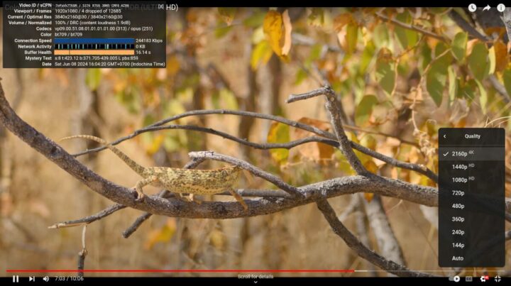
GEEKOM A8 Chrome Linux YouTube 4kp30

As in most modern mini PCs, YouTube 4Kp30 was played smoothly with only 4 frames dropped out of 12,685 when watching the video for a little over 7 minutes.
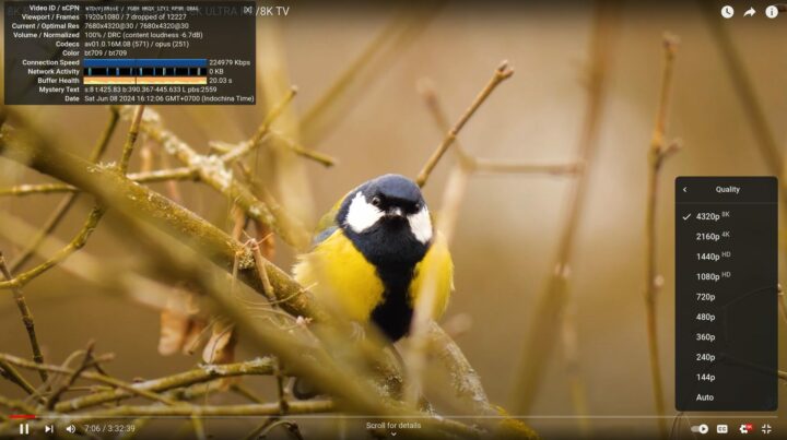
GEEKOM A8 Chrome Linux YouTube 8kp30
8K @ 30 FPS was equally fine with 7 frames dropped out of 12,227.

GEEKOM A8 Chrome Linux YouTube 4kp60

4K @ 60 FPS is still perfectly watchable, but we got a few more dropped frames (107) out of 25,557 during a 7-minute test.

GEEKOM A8 Chrome Linux YouTube 8kp60

8K 60 FPS is often hit-or-miss in your review, and the GEEKOM A8 struggled with that one dropping 2,088 frames out of 11,525.

The GEEKOM A8 had no issues playing the same 8K 60 FPS video in Windows 11/Chrome, but the results are about the same as we had with the GEEKOM A7 with Ubuntu 22.04.

We can evaluate web browsing performance with Speedometer 2.0. Let’s start with Firefox.

GEEKOM A8 Speedometer 2.0 Firefox Ubuntu 24.04

298 runs per minute in Firefox is quite close to the 315 runs per minute the system achieved in the latest version of Google Chrome.

GEEKOM A8 Linux Speedometer 2.0 Google Chrome

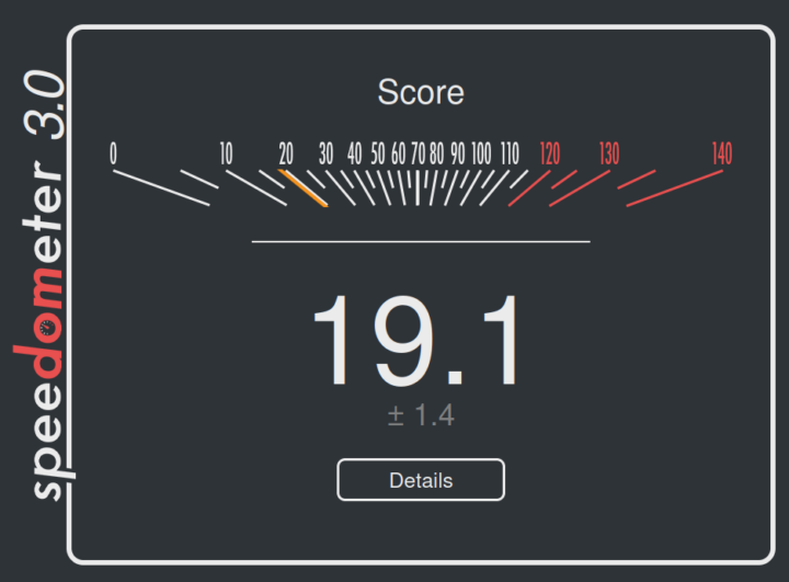
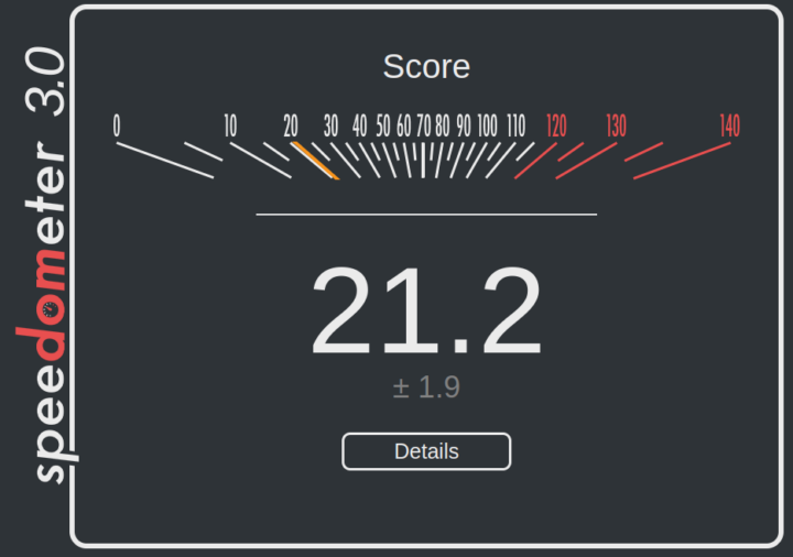
Since Speedometer 2.0 is getting deprecated, we also tested the mini PC with Speedometer 3.0, again with Firefox (19.1 points) and Chrome (21.2 points).
GEEKOM A8 Linux Speedometer 3.0 Firefox
Speedometer 3.0 with Mozilla Firefox
GEEKOM A8 Linux Speedometer 3.0 Google Chrome
Speedometer 3.0 with Google Chrome

It’s important to note that web browser benchmark scores tend to increase over time on the same hardware due to software optimizations in web browsers.

Comparison of GEEKOM A8 benchmarks against other mini PCs running Ubuntu 24.04/22.04

We’ll now compare the Ubuntu 24.04 benchmarks on the GEEKOM A8 against other high-end mini PCs namely the GEEKOM A7 (AMD Ryzen 9 7840HS), the GEEKOM XT12 Pro (Intel Core i9-12900H), the GEEKOM Mini IT13 (Intel Core i9-13900H), and the  Khadas Mind Premium (Intel Core i7-1360P)

Let’s list the main specifications for the 5 machines first.

GEEKOM A8GEEKOM A7GEEKOM XT12 ProGEEKOM Mini IT13Khadas Mind Premium
SoCAMD Ryzen 9 8945HSAMD Ryzen 9 7840HSIntel Core i9-12900HIntel Core i9-13900HIntel Core i7-1360P
CPU8-core/16-thread processor up to 5.2 GHz 8-core/16-thread processor up to 5.1GHz14-core/20-thread (6P+8E) processor up to 5.0 GHz (P-cores), 3.8 GHz (E-Cores)14-core/20-Threads (6P+8E) processor up to 5.4 GHz (P-cores), 4.1 GHz (E-Cores)12-core/16-core (4P+8E) processor up to 5.0 GHz (P-cores), 3.7 GHz (E-Cores)
GPUAMD Radeon 780M GraphicsAMD Radeon 780M Graphics96EU Intel Iris Xe Graphics96 EU Intel Iris Xe Graphics96 EU Intel Iris Xe Graphics
Memory32GB DDR5-560032GB DDR5-560032GB DDR4-320032GB DDR4-320032GB LPDDR5-5200
Storage2TB NVMe SSD2TB NVMe SSD1TB NVMe SSD2TB NVMe SSD1TB NVMe SSD
Default OSWindows 11 ProWindows 11 ProWindows 11 ProWindows 11 ProWindows 11 Home

And now for the benchmark results.

GEEKOM A8GEEKOM A7GEEKOM XT12 ProGEEKOM Mini IT13Khadas Mind Premium
sbc-bench.sh
- memcpy20,318.520,406.022,375.8MB/s24,014.4 MB/s (P-core)25,389.5 MB/s (P-core)
- memset62,156.762,491.727,398.0MB/s26,647.9 MB/s (P-Core)24,731.8MB/s (P-core)
- 7-zip (average)68,79071,11040,19056,54044,430
- 7-zip (top result)69,29772,49643,78360,98150,396
- OpenSSL AES-256 16K1,422,136.66k1,428,559.19k1,661,583.36k (P-Core)1,844,401.49k (P-Core)1,771,334.31k (P-Core)
Geekbench 6 Single2,6612,5352,575
2,7452,093
Geekbench 6 Multi13,27512,91410,44711,9748,891
Unigine Heaven score1,9722,0321,2931,3331,349
Speedometer 2.0 (Firefox)298249298273242

As noted in the Windows review, the GEEKOM A8 and A7 are both powerful mini PCs, but there’s almost no difference in terms of performance between the two. AMD Radeon 780M graphics deliver much better graphics performance than Intel Xe graphics, at least up to the 13th Gen family, as Meteor Lake processors are expected to provide a significant boost in 3D graphics performance.

Storage performance and USB ports testing

The internal 2TB NVMe SSD was tested with iozone3 utility:

aey@geekom-a8-cnx:~$ sudo iozone -e -I -a -s 1000M -r 4k -r 16k -r 512k -r 1024k -r 16384k -i 0 -i 1 -i 2

                                                                    random    random      bkwd     record     stride                                        
              kB  reclen    write    rewrite      read    reread      read     write      read    rewrite       read    fwrite  frewrite     fread   freread
         1024000       4    185511    290432    277682    339847     80622    276209                                                                
         1024000      16    724156    944924   1010209   1019234    271490    848943                                                                
         1024000     512   4539046   4838474   4463116   4526450   3325591   3485303                                                                
         1024000    1024   5005621   5053545   4606076   4686778   4167788   4257071                                                                
         1024000   16384   5269450   4807261   5936029   6162987   6413054   5271282                                                                

iozone test complete.

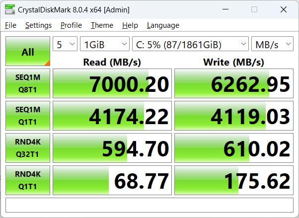
The performance is excellent with 5,936 MB/s sequential read speed and 5,269 MB/s sequential write speed, although as usual, the results with CrystalDiskMark on Windows are higher at  7,000 MB/s และand 6,262 MB/s respectively.

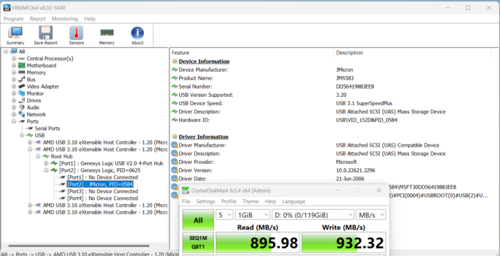
An EXT-4 partition from ORICO M234C3-U4 “USB4” M.2 NVMe SSD enclosure was used to check the speed of each USB port along with lsusb and iozone3 command line utilities. Here’s the output from the front left USB port:

aey@geekom-a8-cnx:~$ lsusb -t | grep uas
        |__ Port 002: Dev 003, If 0, Class=Mass Storage, Driver=uas, 10000M

aey@geekom-a8-cnx:/media/aey/EXT4-REVIEW$ sudo iozone -e -I -a -s 1000M -r 16384k -i 0 -i 1

                                                                    random    random      bkwd     record     stride                                        
              kB  reclen    write    rewrite      read    reread      read     write      read    rewrite       read    fwrite  frewrite     fread   freread
         1024000   16384    930384    925115    818055    819217                                                                                  

iozone test complete.

The 40 Gbps USB4 port on the left side of the rear panel requires us to use the boltctl utility instead of lsusb since the drive is detected as an NVMe drive:

aey@geekom-a8-cnx:~$ boltctl
● Intel USB4.0 SSD
├─ type: peripheral
├─ name: USB4.0 SSD
├─ vendor: Intel
├─ uuid: ba010000-0052-541e-03d5-47dc2cd4b008
├─ generation: Thunderbolt 3
├─ status: authorized
│ ├─ domain: 41283804-400d-604a-ffff-ffffffffffff
│ ├─ rx speed: 40 Gb/s = 2 lanes * 20 Gb/s
│ ├─ tx speed: 40 Gb/s = 2 lanes * 20 Gb/s
│ └─ authflags: none
├─ authorized: Fri 07 Jun 2024 11:34:42 AM UTC
├─ connected: Fri 07 Jun 2024 11:34:42 AM UTC
└─ stored: Fri 07 Jun 2024 11:34:42 AM UTC
├─ policy: iommu
└─ key: no
aey@geekom-a8-cnx:/media/aey/EXT4-REVIEW$ sudo iozone -e -I -a -s 1000M -r 16384k -i 0 -i 1

                                                                    random    random      bkwd     record     stride                                        
              kB  reclen    write    rewrite      read    reread      read     write      read    rewrite       read    fwrite  frewrite     fread   freread
         1024000   16384   2307500   2306924   2452351   2440168                                                                                  

iozone test complete.

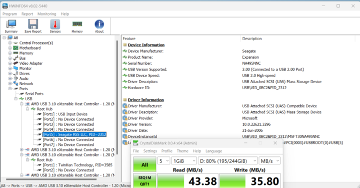
The USB 2.0 port on the rear panel had to be tested with a USB hard drive since the ORICO enclosure is not compatible with USB 2.0 ports:

aey@geekom-a8-cnx:~$ lsusb -t | grep uas
    |__ Port 005: Dev 002, If 0, Class=Mass Storage, Driver=uas, 480M

aey@geekom-a8-cnx:/media/aey/USB3_EXT4$ sudo iozone -e -I -a -s 1000M -r 16384k -i 0 -i 1

                                                                    random    random      bkwd     record     stride                                        
              kB  reclen    write    rewrite      read    reread      read     write      read    rewrite       read    fwrite  frewrite     fread   freread
         1024000   16384     26150     32341     41998     41471                                                                                  

iozone test complete.

Results for the USB ports on GEEKOM A8’s front panel (left to right) in Ubuntu 24.04:

  • USB-A #1 – USB 3.2 – 10 Gbps – 818 MB/s read speed, 930 MB/s write speed
  • USB-A #2 – USB 3.2 – 10 Gbps – 818 MB/s read speed, 930 MB/s write speed

Same tests for the rear panel (left to right):

  • USB-C #1 – Thunderbolt 3/40 Gbps – 2307 MB/s read speed; (The 2452 MB/s write speed should be ignored as it grossly exceeds the advertised speed).
  • USB-A #1 (Top) – USB 3.2 – 10 Gbps – 842 MB/s read speed, 947 MB/s write speed
  • USB-A #2 (Bottom) – USB 2.0 – 480 Mbps – 42 MB/s read speed, 26 MB/s write speed
  • USB-C #2 – USB 3.2 – 10 Gbps – 844 MB/s read speed, 847 MB/s write speed

All USB ports perform as advertised.

2.5GbE and WiFi 6 network performance (plus Bluetooth testing)

We tested 2.5GbE network performance with iperf3 and UP Xtreme i11 Edge mini PC on the other side:

  • Download

aey@geekom-a8-cnx:~$ iperf3 -t 60 -c 192.168.31.12 -i 10 -R
Connecting to host 192.168.31.12, port 5201
Reverse mode, remote host 192.168.31.12 is sending
[  5] local 192.168.31.69 port 59146 connected to 192.168.31.12 port 5201
[ ID] Interval           Transfer     Bitrate
[  5]   0.00-10.01  sec  2.74 GBytes  2.35 Gbits/sec                  
[  5]  10.01-20.01  sec  2.74 GBytes  2.35 Gbits/sec                  
[  5]  20.01-30.01  sec  2.74 GBytes  2.35 Gbits/sec                  
[  5]  30.01-40.01  sec  2.74 GBytes  2.35 Gbits/sec                  
[  5]  40.01-50.01  sec  2.74 GBytes  2.35 Gbits/sec                  
[  5]  50.01-60.01  sec  2.74 GBytes  2.35 Gbits/sec                  
- - - - - - - - - - - - - - - - - - - - - - - - -
[ ID] Interval           Transfer     Bitrate         Retr
[  5]   0.00-60.05  sec  16.4 GBytes  2.35 Gbits/sec    0             sender
[  5]   0.00-60.01  sec  16.4 GBytes  2.35 Gbits/sec                  receiver

iperf Done.

  • Upload

aey@geekom-a8-cnx:~$ iperf3 -t 60 -c 192.168.31.12 -i 10
Connecting to host 192.168.31.12, port 5201
[  5] local 192.168.31.69 port 45520 connected to 192.168.31.12 port 5201
[ ID] Interval           Transfer     Bitrate         Retr  Cwnd
[  5]   0.00-10.01  sec  2.74 GBytes  2.36 Gbits/sec    0    732 KBytes       
[  5]  10.01-20.01  sec  2.74 GBytes  2.35 Gbits/sec    0   1.23 MBytes       
[  5]  20.01-30.01  sec  2.74 GBytes  2.35 Gbits/sec    0   1.23 MBytes       
[  5]  30.01-40.01  sec  2.74 GBytes  2.35 Gbits/sec    0   1.23 MBytes       
[  5]  40.01-50.01  sec  2.74 GBytes  2.35 Gbits/sec    0   1.83 MBytes       
[  5]  50.01-60.01  sec  2.74 GBytes  2.35 Gbits/sec    1   1.28 MBytes       
- - - - - - - - - - - - - - - - - - - - - - - - -
[ ID] Interval           Transfer     Bitrate         Retr
[  5]   0.00-60.01  sec  16.4 GBytes  2.35 Gbits/sec    1             sender
[  5]   0.00-60.05  sec  16.4 GBytes  2.35 Gbits/sec                  receiver

iperf Done.

  • Full-duplex (bidirectional)

aey@geekom-a8-cnx:~$ iperf3 -t 60 -c 192.168.31.12 -i 10 –bidir
Connecting to host 192.168.31.12, port 5201
[  5] local 192.168.31.69 port 35470 connected to 192.168.31.12 port 5201
[ ID] Interval           Transfer     Bitrate         Retr  Cwnd
[  5]   0.00-10.01  sec  2.74 GBytes  2.35 Gbits/sec    0    716 KBytes       
[  5]  10.01-20.01  sec  2.74 GBytes  2.35 Gbits/sec    0   1.59 MBytes       
[  5]  20.01-30.01  sec  2.74 GBytes  2.35 Gbits/sec  411   1.12 MBytes       
[  5]  30.01-40.01  sec  2.74 GBytes  2.35 Gbits/sec    0   1.12 MBytes       
[  5]  40.01-50.01  sec  2.74 GBytes  2.35 Gbits/sec    0   1.12 MBytes       
[  5]  50.01-60.01  sec  2.74 GBytes  2.35 Gbits/sec    0   1.12 MBytes       
- - - - - - - - - - - - - - - - - - - - - - - - -
[ ID] Interval           Transfer     Bitrate         Retr
[  5]   0.00-60.01  sec  16.4 GBytes  2.35 Gbits/sec  411             sender
[  5]   0.00-60.05  sec  16.4 GBytes  2.35 Gbits/sec                  receiver

iperf Done.

No issue here as on most Intel/AMD mini PCs with 2.5GbE ports.

Time to test WiFi 6 in Ubuntu 24.04 on our repaired GEEKOM A8 while connected to a Xiaomi Mi AX6000 router:

  • Download

aey@geekom-a8-cnx:~$ iperf3 -t 60 -c 192.168.31.12 -i 10 -R
Connecting to host 192.168.31.12, port 5201
Reverse mode, remote host 192.168.31.12 is sending
[  5] local 192.168.31.59 port 37768 connected to 192.168.31.12 port 5201
[ ID] Interval           Transfer     Bitrate
[  5]   0.00-10.01  sec  1.76 GBytes  1.51 Gbits/sec                  
[  5]  10.01-20.01  sec  1.77 GBytes  1.52 Gbits/sec                  
[  5]  20.01-30.01  sec  1.83 GBytes  1.58 Gbits/sec                  
[  5]  30.01-40.01  sec  1.82 GBytes  1.56 Gbits/sec                  
[  5]  40.01-50.01  sec  1.88 GBytes  1.61 Gbits/sec                  
[  5]  50.01-60.01  sec  1.89 GBytes  1.63 Gbits/sec                  
- - - - - - - - - - - - - - - - - - - - - - - - -
[ ID] Interval           Transfer     Bitrate         Retr
[  5]   0.00-60.05  sec  11.0 GBytes  1.57 Gbits/sec   22             sender
[  5]   0.00-60.01  sec  11.0 GBytes  1.57 Gbits/sec                  receiver

iperf Done.

  • Upload

aey@geekom-a8-cnx:~$ iperf3 -t 60 -c 192.168.31.12 -i 10
Connecting to host 192.168.31.12, port 5201
[  5] local 192.168.31.59 port 49128 connected to 192.168.31.12 port 5201
[ ID] Interval           Transfer     Bitrate         Retr  Cwnd
[  5]   0.00-10.01  sec  1.55 GBytes  1.33 Gbits/sec   22   2.36 MBytes       
[  5]  10.01-20.01  sec  1.57 GBytes  1.35 Gbits/sec    0   3.01 MBytes       
[  5]  20.01-30.01  sec  1.56 GBytes  1.34 Gbits/sec    0   3.01 MBytes       
[  5]  30.01-40.01  sec  1.57 GBytes  1.35 Gbits/sec    0   3.01 MBytes       
[  5]  40.01-50.01  sec  1.54 GBytes  1.33 Gbits/sec    0   3.01 MBytes       
[  5]  50.01-60.01  sec  1.54 GBytes  1.32 Gbits/sec    0   3.01 MBytes       
- - - - - - - - - - - - - - - - - - - - - - - - -
[ ID] Interval           Transfer     Bitrate         Retr
[  5]   0.00-60.01  sec  9.34 GBytes  1.34 Gbits/sec   22             sender
[  5]   0.00-60.05  sec  9.34 GBytes  1.34 Gbits/sec                  receiver

iperf Done.

Outstanding WiFi 6 performance with 1.57 Gbps downloads and 1.34 Gbps uploads, one of the best results in our test environment.

What’s not as nice is that Bluetooth 5.3 does not work. GEEKOM keeps releasing mini PCs with MediaTek MT7922 which does not support Bluetooth in Linux.

GEEKOM A8 Ubuntu bluetooth not working

An error also shows in the kernel log:

aey@geekom-a8-cnx:~$ dmesg | grep -i bluetooth
[    6.751709] Bluetooth: Core ver 2.22
[    6.751731] NET: Registered PF_BLUETOOTH protocol family
[    6.751733] Bluetooth: HCI device and connection manager initialized
[    6.751736] Bluetooth: HCI socket layer initialized
[    6.751738] Bluetooth: L2CAP socket layer initialized
[    6.751741] Bluetooth: SCO socket layer initialized
[    8.273704] Bluetooth: BNEP (Ethernet Emulation) ver 1.3
[    8.273709] Bluetooth: BNEP filters: protocol multicast
[    8.273715] Bluetooth: BNEP socket layer initialized
[    8.869373] Bluetooth: hci0: Opcode 0x0c03 failed: -110

But there’s hope, as Ian Morrison submitted a patch to the Linux kernel mailing list last March, and it might be released as part of Linux 6.10. So if you absolutely need Bluetooth, you could always try to build the Linux kernel manually with this patch. But that’s out of the scope of this review…

Stress test and thermal performance

We ran a stress test on the 16 threads of the AMD Ryzen 9 8945HS processor to evaluate thermal performance by monitoring the CPU temperature with psensor and the CPU frequency with the sbc-bench.sh script.

GEEKOM A8 Ubuntu Stress Test
The frequency quickly stabilized at 4000 MHz (base frequency) and the CPU temperature at 92°C with the fan rotating at max speed. The maximum temperature was quickly reached as shown when looking at the sbc-bench.sh -m command when starting the test.

sbc bench GEEKOM A8 temperature frequency

Fan noise

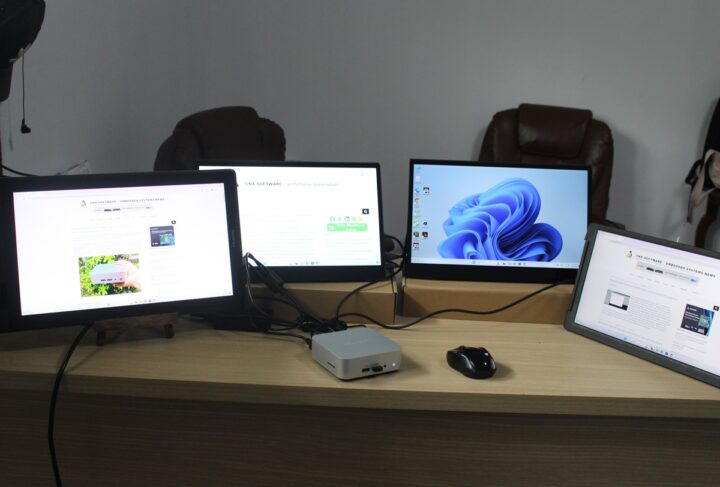
The GEEKOM A8 is not too noisy at idle or under light loads but it’s quite noisy under heavier loads We measured the fan noise with a sound level meter placed at around 5 centimeters from the top of the enclosure:

  • Idle – 38.3 – 39.2 dBA
  • YouTube 8Kp60 video in Chrome – 54.0 – 57.1 dBA
  • Stress test on all 16 threads – 46.6 – 58.0 dBA

For reference, the meter measures around 37 – 38 dBA in a quiet room. The GEEKOM A8 appears to be quieter at idle (the fan does not rotate or very slow), but noisier under heavy loads compared to the GEEKOM A7.

GEEKOM A8 power consumption in Ubuntu 24.04

We measured the power consumption with a wall power meter:

  • Power off – 1.5 Watt
  • Idle – 4.3 – 4.9 Watts
  • Video playback – 61.3 – 67.8 Watts (Youtube 8K 60fps in Chrome)
  • CPU stress test (stress -c 16)
    • First 30 seconds – 60.1 – 70.4 Watts
    • Longer run – 54.5 – 59.0 Watts

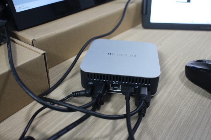
During the measurements, the mini PC was connected to WiFi 6, one RF dongle for a keyboard, one USB mouse, and a CrowVi portable display connected to HDMI and its own power adapter. The power draw with the stress test does not evolve as much under load as with the GEEKOM A7 whose power draw would further drop after a few minutes, and then more after 12 minutes.

Conclusion

The GEEKOM A8 is one of the most powerful mini PCs reviewed on CNX Software (together with GEEKOM A7) and we’ve found it to work well in Ubuntu 24.04 except for Bluetooth not working due to drivers issues with the MediaTek MT7922 wireless module (Azurewave AW-XB591NF). That’s something that might be fixed something next month with a new Linux kernel release. The good news is that the WiFi 6 issues we had with the GEEKOM A7 on Ubuntu 22.04 (with the same module) are all gone in Ubuntu 24.04.

Apart from the Bluetooth issue, the AMD Ryzen 9 8945HS mini PC is great in Linux with fast NVMe storage, excellent multi-core performance, and YouTube video playback works well up to 4K 60 FPS and 8K 30 FPS. Sadly the 8K 60 FPS YouTube video we tried did not play smoothly possibly because of the high room temperature (28°C). The mini PC’s fan is relatively quiet most of the time but gets quite noisy under load. One downside for the GEEKOM A8 is that the GEEKOM A7’s features, performance, and price are all in the same range, so I’m not convinced it brings anything new (apart from a different CPU and cooling system) even if it’s technically a new mini PC…

We’d like to thank GEEKOM for sending us the A8 mini PC for review with an AMD Ryzen 9 8945HS, 32GB DDR5, and a 2 TB SSD. The model reviewed here can be purchased on Amazon for $806.55 with coupon code CNXSWGA8, and you’ll also find it on the GEEKOM US and GEEKOM UK stores with similar pricing when using the discount coupon CNXA8 for a 5% discount. The coupon codes are valid until July 10, 2024. A cheaper GEEKOM A8 model based on the Ryzen 7 8845HS CPU is also available.

CNXSoft: This article is a translation – with some additional insights – of the original review on CNX Software Thailand by Suthinee Kerdkaew.

The post GEEKOM A8 Review – Part 3: Ubuntu 24.04 tested on an AMD Ryzen 8945HS mini PC appeared first on CNX Software - Embedded Systems News.

Dual Micro HDMI to HDMI adapter supports Raspberry Pi 5/4B, offers multiple power options

Micro HDMI to HDMI Multifunctional Adapter for Raspberry Pi 5 or Pi 4B

Waveshare Pi5 Connector Adapter is a compact dual Micro HDMI to HDMI adapter for the Raspberry Pi 5 or Pi 4B that connects to the micro HDMI and USB-C ports simultaneously and provides access to two full-sized HDMI ports. The PCB also features a USB-C port and a screw terminal for power.

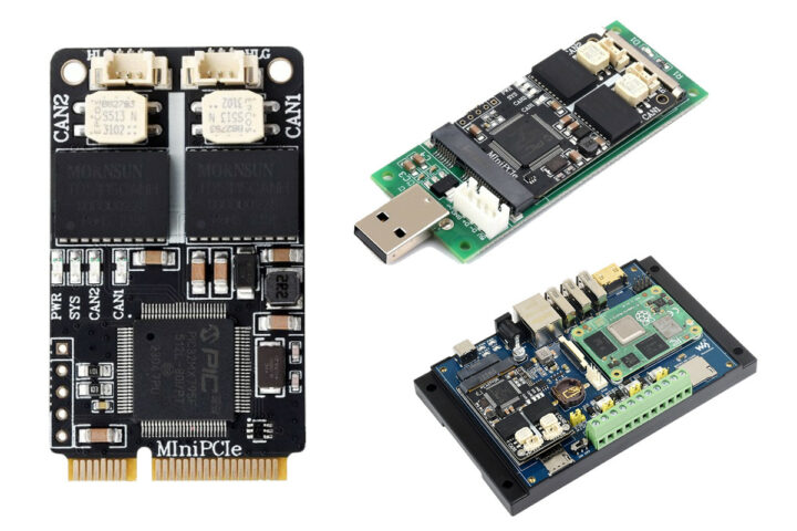
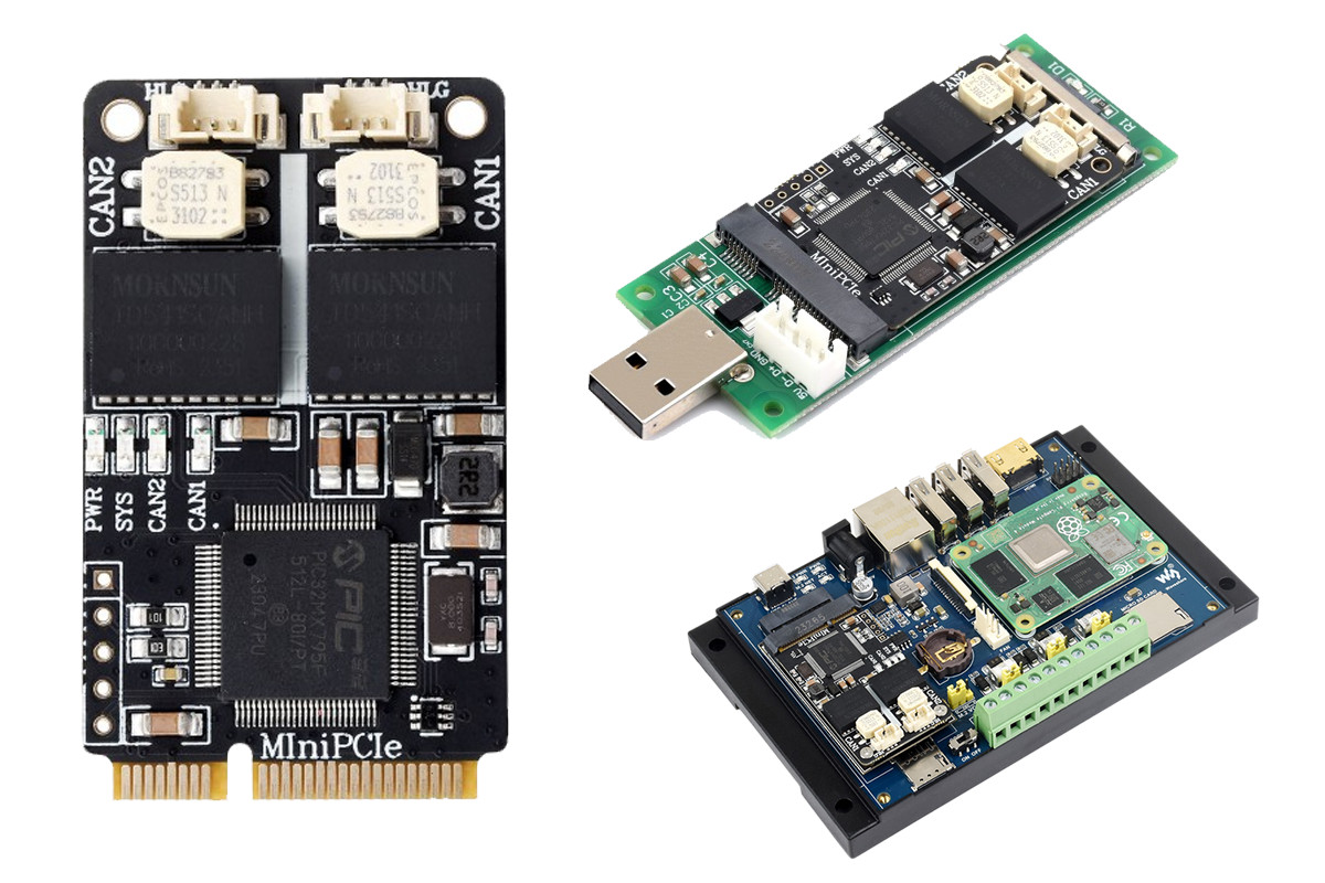
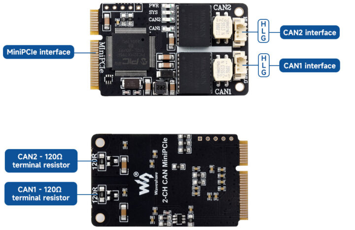
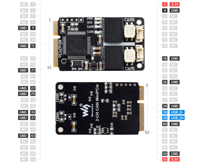
Previously, we have written about many unique waveshare products, including Waveshare 2-CH CAN MiniPCIe, the Waveshare UGV Rover, the Waveshare ESP32-C6-Pico and Pico-M boards and many others, feel free to check those out if you are interested in the topic.

Micro HDMI to HDMI Multifunctional Adapter for Raspberry Pi 5 or Pi 4B

Waveshare Micro HDMI to HDMI adapter specifications

  • Supported Pi – Raspberry Pi 5 / Pi 4B
  • Display Interfaces
    • 2x micro-HDMI inputs
    • 2x HDMI outputs
  • Misc – 2x 3-pin UART connectors
  • Power
    • Power input
      • 1x USB-C female port (Power In)
      • 5 mm box-type screw terminal
      • JST connector for battery
    • Power Output – 1x USB-C male port (Power out)
  • Dimensions – 85.00 mm x 33.5 mm

Pi5 Connector Adapter details 3

The Micro HDMI to HDMI adapter features a PCB with two male micro-HDMI ports and a male USB-C port that enables a direct, cable-free connection to both the micro-HDMI and USB-C ports on the Raspberry Pi 5 board.

Pi5 Connector Adapter details size

The Waveshare Micro HDMI to HDMI Multifunctional Adapter package includes a Pi5 Connector Adapter, a 100mm 3-pin cable, and a 100mm 3-pin squid cable. These components enable seamless connectivity and versatility for enhanced multimedia experiences. In the board, we also find two additional box-type JST connectors that are the breakout for the UART from the Raspberry Pi.

The Waveshare Pi5 Connector Adapter board can be purchased on Aliexpress for $5.88 shipped , on Amazon for $12.99. and on Waveshare’s official store.

The post Dual Micro HDMI to HDMI adapter supports Raspberry Pi 5/4B, offers multiple power options appeared first on CNX Software - Embedded Systems News.
ThingPulse Pendrive S3 ESP32-S3 USB stick comes with 128MB of storage and a capacitive spring button

ThingPulse ESP32-S3 Pendrive spring button

The Pendrive S3 is an ESP32-S3 development board in a USB stick enclosure with 128MB of flash memory and an unusual capacitive touch button. The Espressif ESP32-S3-MINI-1 module on the board integrates an Xtensa dual-core 32-bit LX7 microprocessor with support for 2.4GHz Wi-Fi and Bluetooth 5 (low-energy).

PendriveS3 PCB

The device features a capacitive touch button that can be used to trigger actions by touching the enclosure. The capacitive button isn’t visible on the exterior of the device, which helps the device maintain a low profile. You may be interested in Dani Eichhorn’s article on how he came up with the idea of using a spring for the capacitive touch button.

ThingPulse ESP32-S3 Pendrive spring button

The Pendrive S3 stick can be used as a BadUSB device for hacking and penetration testing purposes. With the aid of SuperWiFiDuck, it can perform keystroke injection attacks. All scripts can be managed and controlled wirelessly via a web interface, and run immediately when the device is plugged in, or when the onboard button is pressed. Other potential applications include a memory stick with cloud sync, a Wi-Fi dongle, and a password manager.

It uses the open-source USB stack, TinyUSB, to emulate several device classes such as Human Interface Device (mice, keyboards), Mass Storage, Video, and Network. It is supported by CircuitPython, a subset of Python that is lightweight and optimized for microcontrollers.

Other interesting devices in a USB stick form factor include the Waveshare RP2040-GEEK, the T-Dongle ESP32-S2, and Ovrdrive USB.

ThingPulse Pendrive S3 specifications:

  • Wireless module – ESP32-S3-MINI
    • CPU – Dual-core Xtensa LX7 @ 240 MHz,
    • Wireless – 2.4GHz Wi-Fi and Bluetooth 5 (LE)
    • Memory/Storage – 512 KB SRAM, 8MB on-chip flash,
    • PCB antenna
  • Storage – 128MB flash memory, addressable via SDIO/MMC or SD card interface, in 1-bit or 4-bit mode
  • USB – USB-C male connector
  •  Misc
    • WS2812B addressable RGB LED
    • Capacitive touch button (Spring)
  • USB drive plastic enclosure


The Pendrive S3 is priced at $25 on the ThingPulse website. It is not a perfect device, but it can be useful for tinkering and experimentation. CNX readers can get a 20% discount by using the coupon code cnx-pendrive-s3 during checkout.

The post ThingPulse Pendrive S3 ESP32-S3 USB stick comes with 128MB of storage and a capacitive spring button appeared first on CNX Software - Embedded Systems News.
LattePanda Mu review – Part 1: an Intel N100 Compute Module tested with Windows 11, carrier boards with PCIe slots

LattePanda Mu Full Carrier Windows 11 Review

Last April, DFRobot launched the LattePanda Mu x86 Compute Module powered by an Intel N100 Alder-Lake processor with 8GB RAM and a 64GB eMMC flash along with Lite and Full function carrier boards for evaluation. End customers will typically design their own carrier board without having to take of high-speed signals for the LPDDR5 memory and other complexities during the PCB layout.

DFRobot has sent us the LattePanda Mu module for review along with the Lite and Full Function carrier boards, a heatsink for passive cooling, and an active cooler so we can compare both cooling solutions.  Let’s have a look at the LattePanda Mu module and accessories before testing the kit with the Windows 11 operating system, including the PCIe x4 slot.

LattePanda Mu kit unboxing

LattePanda Mu Unboxing
The parcel included three retail boxes.

LattePanda Mu Board Accessories
The smallest box housed the LattePanda Mu Compute Module, a heatsink, and an active cooler.

LattePanda Mu Carrier Board Fan Heatsink
The second orange box contained a kit with the Lite carrier board.

Full Feature Carrier Board
The large black box included the Full Function evaluation carrier board which should enable users to test all features supported by the LattePanda Mu.

Hardware overview

LattePanda Mu Compute Module

The LattePanda Mu system-on-module (SoM) comes in a 69.6 x 60mm SO-DIMM DDR4 form factor that is smaller than a credit card. Many SoM manufacturers will use SO-DIMM DDR4 form factor but note that each will assign pins as they see fit and modules from different brands are usually not pin-to-pin compatible. The Intel N100 Alder Lake-N CPU on the LattePanda Mu board is a low-power SoC commonly used in entry-level laptops, mini PCs, and NAS systems.

LattePanda Mu Intel Processor N100 System-on-Module
You can check out the full specifications for the LattePanda Mu in our previous article and we also included the block diagram below for reference.
Lattepanda mu block diagram
Besides the Intel processor, some other components can be found on the LattePanda Mu board including a power management module (MP2964), KLMG2UCTA-B041 eMMC flash, 8GB LPDDR5 RAM, and a Winbond 25Q128 EEPROM.
chip mp2964 emmc memory eeprom

Cooling solutions

DFRobot provides two cooling solutions for the LattePanda Mu module: a heatsink and an active cooler.

LattePanda Mu heatsink

The heatsink used for passive cooling (i.e. fanless system) measures 70  x 45.5 x 33 mm and features three spring-loaded screws for installation on the x86 module. The company claims a 6W TDP CPU will operate at up to 35°C, and a 10W TDP chip at up to 35°C when the heatsink is fitted.

LattePanda Mu heatsink
Active cooler

The active cooler combines a 69.6 x 50.4 x 19 mm heatsink with a 4000 rpm fan and 3 spring-loaded screws for installation on the LattePanda Mu SoM. The company did not list any cooling performance metric on its website, but we’ll test that later.

LattePanda active cooler

Operating system installation on the LattePanda Mu

Since the LattePanda Mu module is powered by an Intel N100 processor with an x86-64 architecture, we can install any operating system just like on a normal computer. We will test the screen, keyboard, and mouse. We’ll start testing with the Lite carrier board using a USB-C PD adapter instead of a 12V adapter.

LattePanda Mu peripheral setup
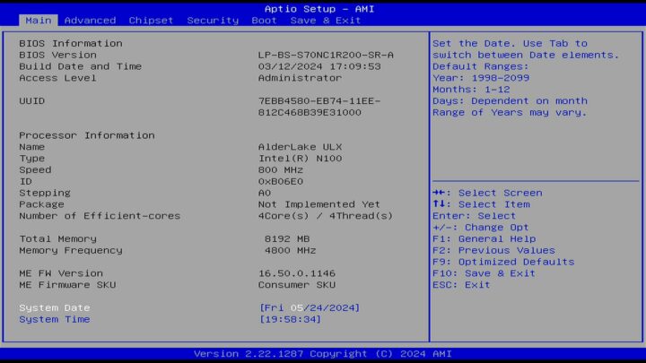
That means we can select any OS image without customization for this specific board. We can access the BIOS (Aptio Setup) to view basic information as shown in the picture below.

LattePanda mu BIOS
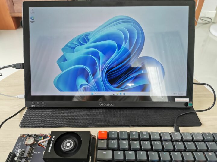
After setting the system date/time, we tested and booted into the operating system pre-installed on the eMMC flash. That would be Windows 11…

LattePanda mu Windows 11 desktop
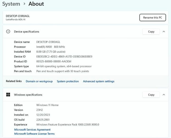
More exactly, the system is running Windows 11 Home 64-bit on a system with a 800MHz (base frequency) Intel N100 processor and 8GB of RAM.

Intel N100 SBC Windows 11
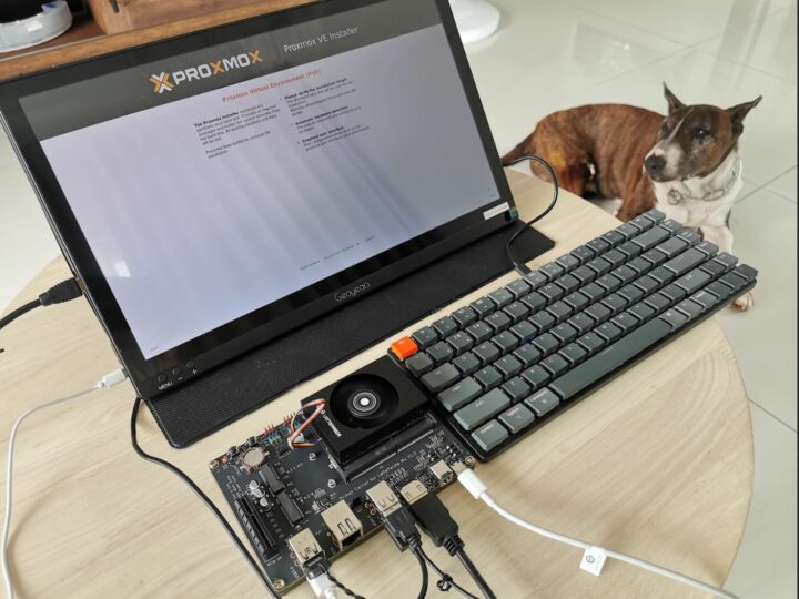
We then decided to reboot the system and install Proxmox which could be installed in the same way as on any other x86 computer.

LattePanda Mu Proxmox Setup
LattePanda Mu SoM tested with the Lite Carrier Board

The Lite Carrier Board comes with the following features:

  • Wide voltage input
    • 15V up to 3A via USB Type-C port
    • 12 to 20V up to 10A via 5.5×2.5mm DC jack
  • PCIe 3.0 x4 slot (only available when using 12V power supply)
  • M.2 M Key 2230 (PCIe 3.0 x1)
  • M.2 E Key 2230 (PCIe 3.0 x1, USB2.0)
  • RTC battery socket for 3V CR1220 coin cell
  • CPU fan socket
  • 4-pin Gravity connectors for  UART and I2C modules
  • USB – 2x 10 Gbps USB 3.2 ports, 2x USB 2.0 ports
  • Gigabit Ethernet RJ45 jack
  • 3.5-inch embedded motherboard standard size

We’ll now do some general usage testing of the Lite Carrier Board with the LattePanda Mu module, an M.2 WiFi card, and a PCIe card.

LattePanda Mu lite carrier m2 SSD test
We installed a Realtek RTL8822CE WiFi and Bluetooth module into the M.2 B key slot and Windows 11 automatically detected and installed the drivers without the users having to do anything manually.

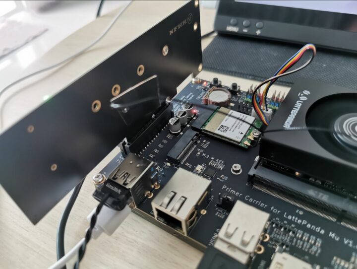
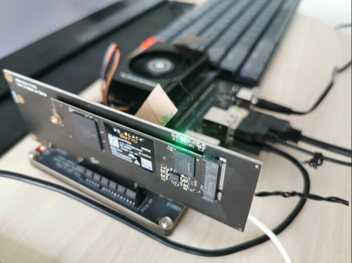
LattePanda mu lite carrier PCIe test
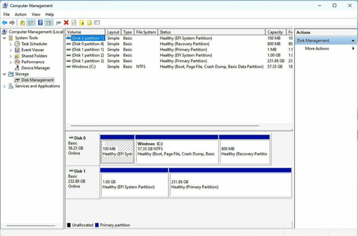
The PCIe Gen 3.0 x4 slot was tested with an NVMe to PCIe adapter fitted with a 250GB WD Black SN770 SSD installed. The first time after booting the device was not detected. So I opened the online manual of LattePanda Mu and found a warning that using the device via the PCIe slot requires connecting a 12V adapter, and it would not work with a USB-C power supply. So I turned off the machine and changed the power source to a 12V adapter. The drive (Disk 1) was properly detected after I restarted the system.

LattePanda mu lite carrier PCIe test result
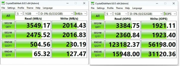
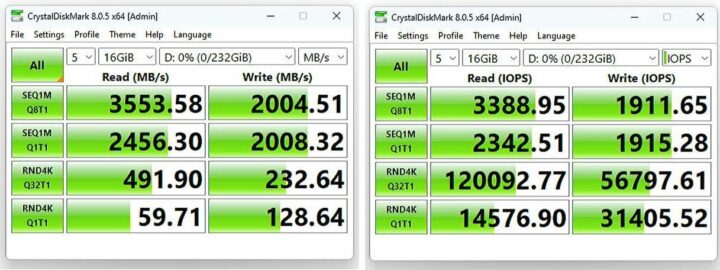
We tested the sequential reading and writing speeds of the SN770 SSD with CrystalDiskMark 8.0.5. The SN770 NVMe SSD supports PCIe 4.0 with a sequential read speed of up to 4,000 Mbps and a sequential write speed of up to 2,000 Mbps. However, since the LattePanda Mu module only supports PCIe 3.0 x4, we won’t be able to reach that level of performance, but we’ll get close…

LattePanda Mu PCIe SSD test
Performance with 1GB size
LattePanda Mu PCIe SSD test 16 GB
Performance with 16GB size

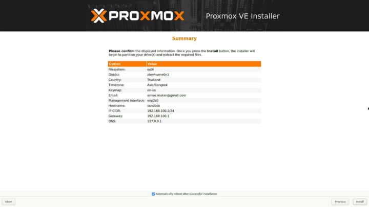
CrystalDiskMark 8.0.5 shows that the disk’s sequential read/write speed is pretty good (from the datasheet: Sequential Read speeds of 4,000 MBps and Sequential Write speeds of 2,000 MBps, IOPS Random Read speeds of 470,000 IOPS and Random Write speeds of 240,000 IOPS), even though it is connected to a PCIe 3.0 x4 slot since it has a 4GB/s theoretical limit. The next step is to test the installation of Proxmox and the NVMe drive (/dev/nvme0n1) is detected properly.

Proxmox installation test

Testing the LattePanda Mu SoM with the Full-Function evaluation board

The Full-Function Evaluation board comes with the following features:

  •  Front I/O Interfaces
    • Audio
      • 3.5mm microphone interface
      • 3.5mm headphone interface
    • USB
      • 2x USB 2.0
      • 4x USB 3.0
      • 1x USB 3.0 Type-C port with DisplayPort alt mode
    • Serial – RS232 DB9 connector
    • Connectivity – SIM card slot
  • Rear I/O Interfaces
    • Video Outputs – 2x HDMI 2.0
    • Networking- 2.5GbE RJ45 ports via Intel controllers
    • Misc – Power button
    • Power Supply
      • 5.5×2.5mm DC jack
      • Screw Terminal Plug
  • Expansion slots
    • PCIe 3.0 x1 slot
    • PCIe 3.0 x4 slot (multiplexed with the SATA signals)
    • M.2 E Key slot with support for 2230 WLAN card (PCIe 3.0 x1, USB 2.0; multiplexed with the Ethernet port 2 (RJ45_2) signals)
    • M.2 B Key slot with support for 3042/3052 4G LTE/5G WWAN card (USB 3.0, USB 2.0)
    • 2x SATA 6Gb/s interfaces (multiplexed with the PCIe 3.0 x4 signals)
  • Various headers, jumpers, and buttons
  • Dimensions – 170 x 170mm (mini-ITX form factor)
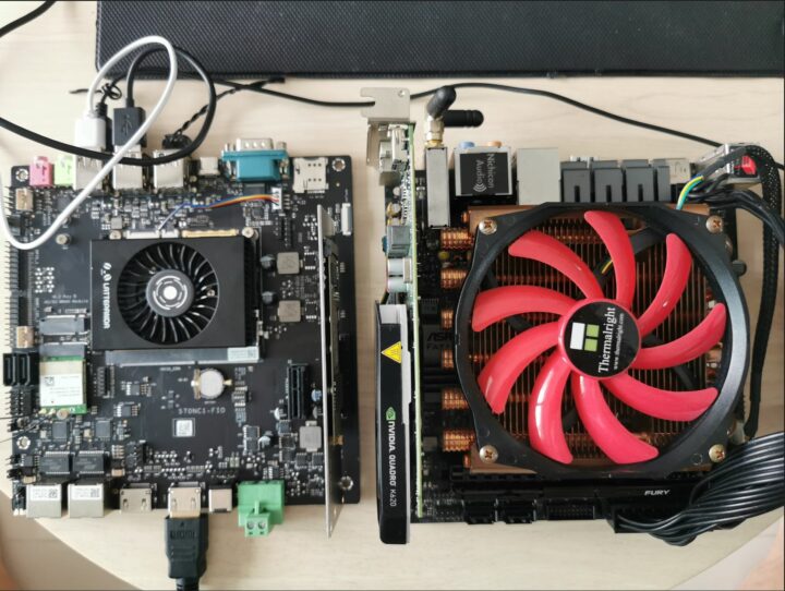
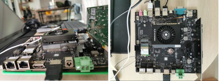
LattePanda Mu full carrier vs mini-ITX board
LattePanda Mu full carrier vs other mini-ITX board

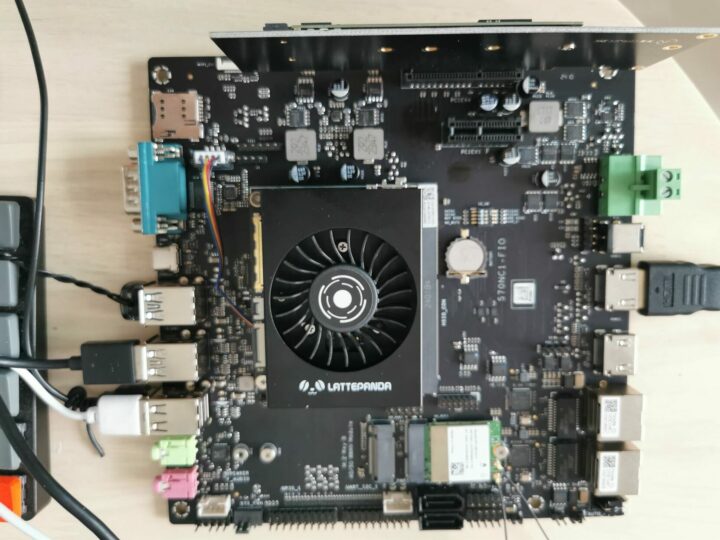
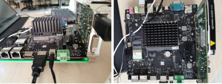
LattePanda mu full carrier top view

Since the Full-function board is larger than the Lite board, more connectors and ports are available including two Gigabit Ethernet ports, two HDMI video outputs, and PCIe 3.0 x4 and x1 slots. Some interfaces are multiplexed and configurable through a DIP switch as shown in the table below.

SATA1PCIe X4Set to SATA1 for SATA selection
Set to PCIe x4 for PCIe x4 section
SATA2PCIe X4Set to SATA2 for SATA selection
Set to PCIe x4 for PCIe x4 section
BOT BIOSCORE BIOSSet to BOT BIOS to use the BIOS on the evaluation board
Set to CORE BIOS to use the BIOS on the LattePanda Mu
M2 Wi-FiRJ45_2Set to M2 Wi-Fi to use a Wi-Fi module
Set to RJ45_2 to use the second Ethernet port

LattePanda Mu Full Function Carrier NVIDIA Quadro PCIe graphics card

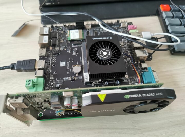
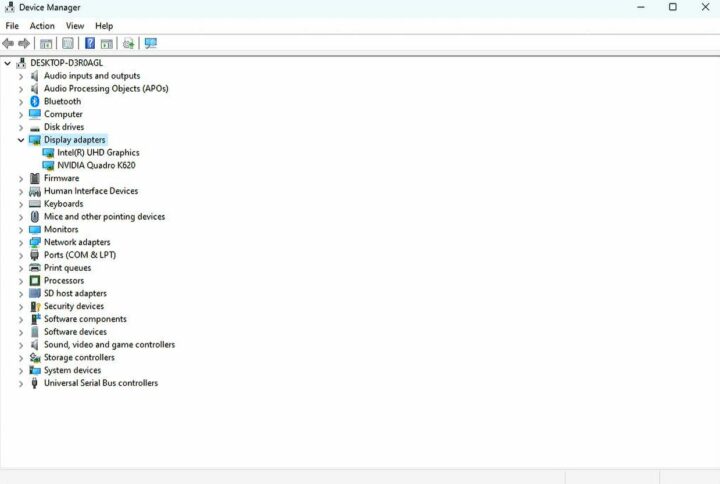
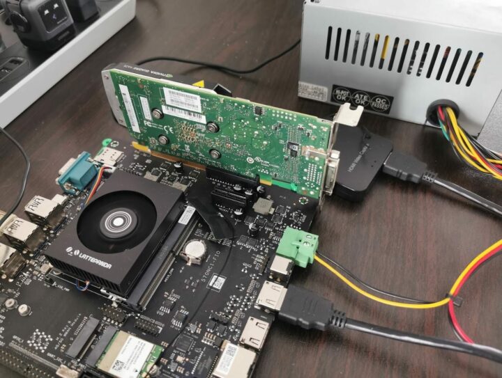
We than plugged an NVIDIA Quadro K620 graphics card into the PCIe 3.0 x4 slot. The card was recognized in Windows 11 and the drivers were installed automatically.

NVIDIA Quadro K620 Windows 11 Device Manager

However, the system failed to run any graphics benchmarks and crashed for each one we tested. We’ll go through this and explain how it was fixed a little further below.

Test the efficiency of the cooling systems

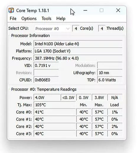
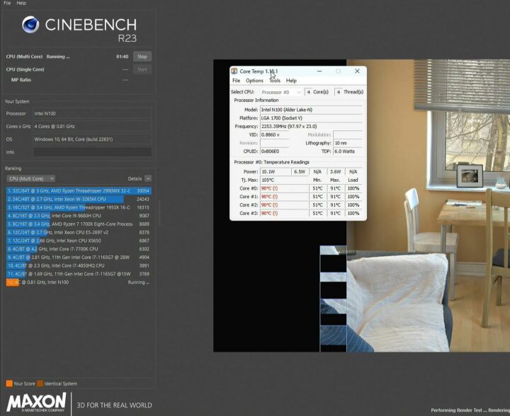
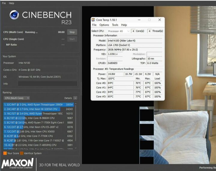
The LattePanda Mu comes with two cooling solutions. So we tried both while running the Cinebench R23 program and checking whether the system could operate at optimal performance using the Core Temp program to monitor the CPU temperature.

LattePanda Mu Full Carrier Windows 11 Review

The CPU temperature will be around 40°C while the system is idle whether using the heatsink or active cooler.

Intel N100 active cooling CPU IDLE temperature

Let’s run the Cinebench R23 multi-core benchmark to stress test the system with the heatsink (passive cooling/fanless mode).

LattePanda Mu passive cooling

LattePanda mu active cooling cinebench

The Core Temp program reports the CPU temperature goes up to 91° Celsius. So the heatsink may not be suitable for use cases where the system operates at 100% load over long periods of time.

Let’s now switch to the active cooler and repeat the same test.

LattePanda Mu active cooling

LattePanda Mu active cooling cinebench R23

The Core temp program reports a CPU temperature up to 87° Celsius, and typically at 84 to 85°C under load. It’s a PWM fan, so it rotates slowly under light loads, and faster under load. This cooling solution is better suited for workloads that require the system to operate at 100% CPU load over extended periods.

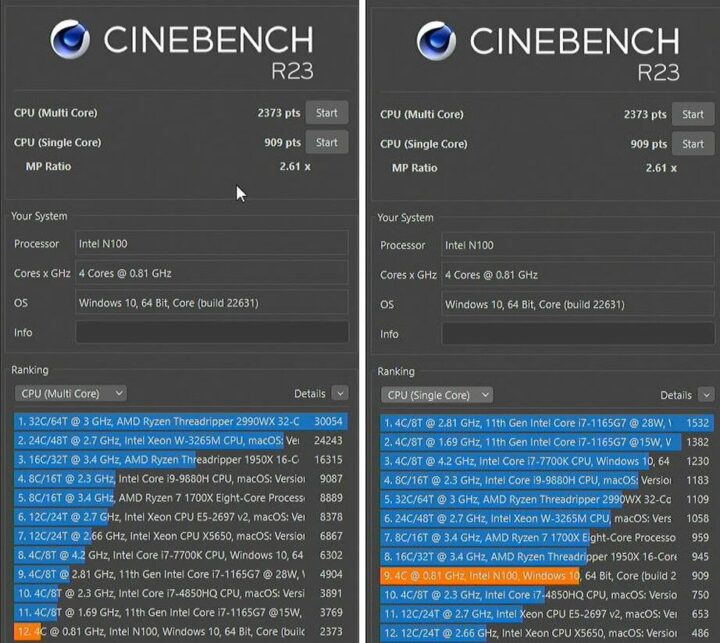
Here are the results for the single-core and multi-core benchmarks for reference.

LattePanda mu active cooling cinebench multicore result

Those scores are somewhat lower than the ones for other Intel N100 mini PCs we’ve tested, especially the multi-core score.

3Dmark benchmark with Intel iGPU and Quadro K620 graphics card

We will now test the 3D graphics performance of the Intel UHD graphics and NVIDIA Quadra K620 graphics cards. We previously mentioned that all 3D graphics benchmarks would crash with the Quadro K620 card. That’s because we used a 12V/3A power supply, and the graphics card draws up to 45W of power (See PDF datasheet). That card will not need to be connected to the PSU in a standard PC since a PCIe slot can deliver up to 75W, but we used an underpowered power adapter which led to the crashes.

LattePanda Mu PC power supply
LattePanda Mu connected to computer power supply and graphics card. We’ll use the active cooler during this test.

After switching to a computer power supply with 12V output and capable of outputting a current of over 10A, 3D graphics benchmarks such as 3DMark could run properly.

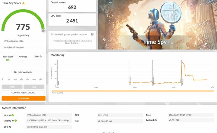
LattePanda Mu NVIDIA Quadro K620 3DMark Time Spy

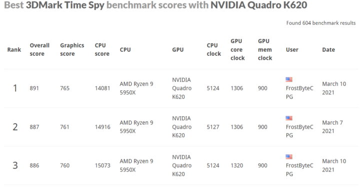
The overall score is 775 points for 3DMark Time Spy with a Graphic score of 692 points and a CPU score of 2,451 points. While the Intel N100 is a low-end system with a PCIe 3.0 x4 slot, the graphics card features a PCI Express 2.0 x16 interface and the results are not that much different than on higher-end systems with Graphics scores ranging between 694 and 765.

3DMark Spy Time Graphics score rankings with NVIDIA Quadro K620

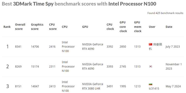
This may have been a different story with a more modern and powerful graphics card. Let’s compare the LattePanda Mu score (2,451 points) against other Intel N100 systems whose score ranges between 1,405 and 2,598 points. The LattePanda Mu board is near the top of the range meaning cooling works well.

Intel N100 3DMark Time Spy CPU ranking

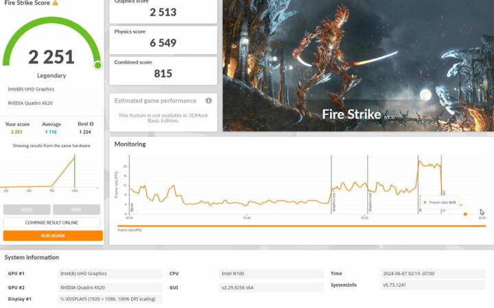
We’ll now run 3DMark Fire Strike since it’s the default test for all our Windows reviews. The LattePanda achieved 2,251 points with the Quadro K620 graphics card including 2,513 points for the Graphics score and 6,549 points for the Physics score.

LattePanda Mu 3dmark Fire Strike with Quadro K620

That’s an improvement over the iGPU, but not overly so, as the Intel N100-powered MINIX Z100-0dB and GEEKOM Mini Air 12 mini PCs achieved 1,125 and 1,188 points respectively in the same test.

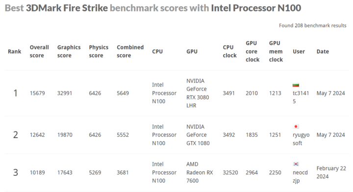
The Physics score mostly relies on the CPU and the LattePanda Mu’s score of 6,549 points is similar to the scores of other Intel N100 systems.

Intel N100 3dmark fire strike CPU ranking

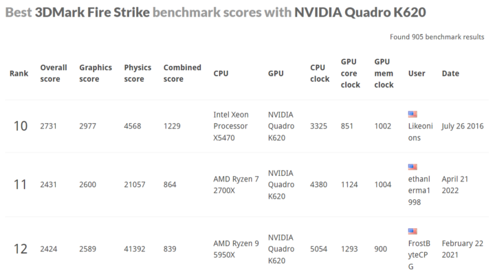
The Graphics score (2,513 points) is barely lower than in other computers with the same Quadro K620 GPU and (sometimes) a much more powerful CPU.

3dmark fire strike Quadro K620 GPU ranking

Conclusion

DFRobot LattePanda Mu system-on-module is offered with open-source hardware (KiCad) carrier boards that can serve as a starting point for companies wanting to create their own carrier boards. The carrier and module can also be used directly for a range of applications such as a home server, mini PC, IoT gateway, and more.

The low-power platform is versatile thanks to its PCIe Gen x4/x1 slots, GPIO header with UART, I2C, etc.., and a wide range of ports. In the Windows 11 review, we successfully tested the PCIe x4 slot with an NVIDIA Quadro K620 graphics card after selecting a proper PSU and also tested the passive and active cooling solutions provided by DFRobot. The heatsink can create a fanless system, but for optimal performance under sustained heavy loads, the active cooler is recommended.

We’ll install Ubuntu 24.04 in the second part of the LattePanda Mu review. We’ll then run some benchmarks to compare it more fully against other Alder Lake-N systems and test the GPIO headers with interfaces such as UART and I2C among other tests.

We’d like to thank DFRobot for sending the LattePanda Mu module, carrier boards, and accessories for review. The LattePanda Mu x86 Compute Module can be purchased for $139 on DFRobot, but most people will first purchase a complete kit that can be customized, and for instance, a kit with the LattePanda Mu SoM, Full-Function carrier board, heatsink, and 19W/90A power supply can be had for $274.90. Alternatively, you’ll find a $199 kit on Amazon with the SoM, Lite carrier board, and active cooler.

CNXSoft: This review is a translation – with a few additional insights – of the original article on CNX Software Thailand by Arnon ThongTem, edited by Suthinee Kerdkaew.

The post LattePanda Mu review – Part 1: an Intel N100 Compute Module tested with Windows 11, carrier boards with PCIe slots appeared first on CNX Software - Embedded Systems News.
How to repair/replace a WiFi antenna in a mini PC

Insert WiFi Antenna Mini PC

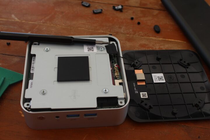
In this short tutorial, we’ll show how to repair/replace a WiFi antenna in a mini PC. We’ll use GEEKOM A8 Mini PC as a test device because one of its WiFi antennas is attached to the top plastic cover, and it may potentially get damaged when the user opens the case to change or upgrade the SSD or memory sticks.

GEEKOM A8 mini PC teardown

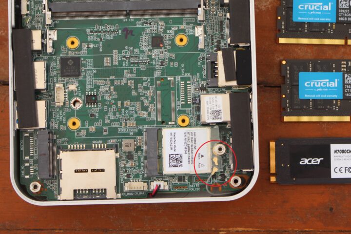
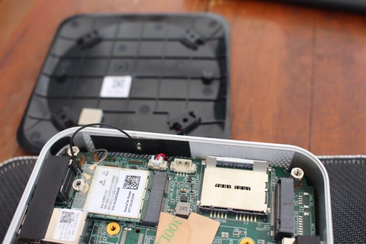
This happened to us during the teardown of the GEEKOM A8 mini PC as shown in the image below.  While WiFi still works with one antenna, the performance is quite better when two antennas are connected so we decided to repair the mini PC.

Broken wifi antenna mini PC

We asked a few local shops, but they would only sell WiFi modules with antennas and none would just sell the antennas themselves. But luckily, such WiFi antennas can easily be purchased online in pairs.

IPEX1 WiFi Antennas

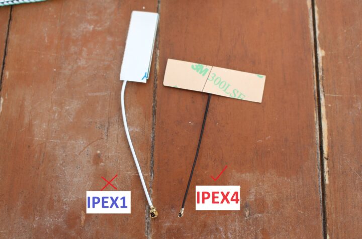
The first time, we purchased a WiFi antenna pair from Shopee (an Aliexpress equivalent in Thailand) seeing it would work with WiFi modules installed in mini PCs and laptops. But the antenna we purchased comes with an IPEX1 connector which is not compatible with the MediaTek module found in the GEEKOM A8, and require an antenna with a smaller IPX4/MHF4 connector as shown below.

WiFi Antenna IPEX1 vs IPEX4

So readers should first find out which model of antenna they need for their specific model.

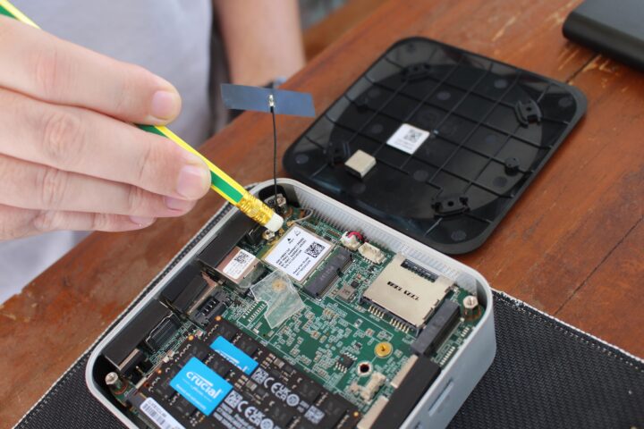
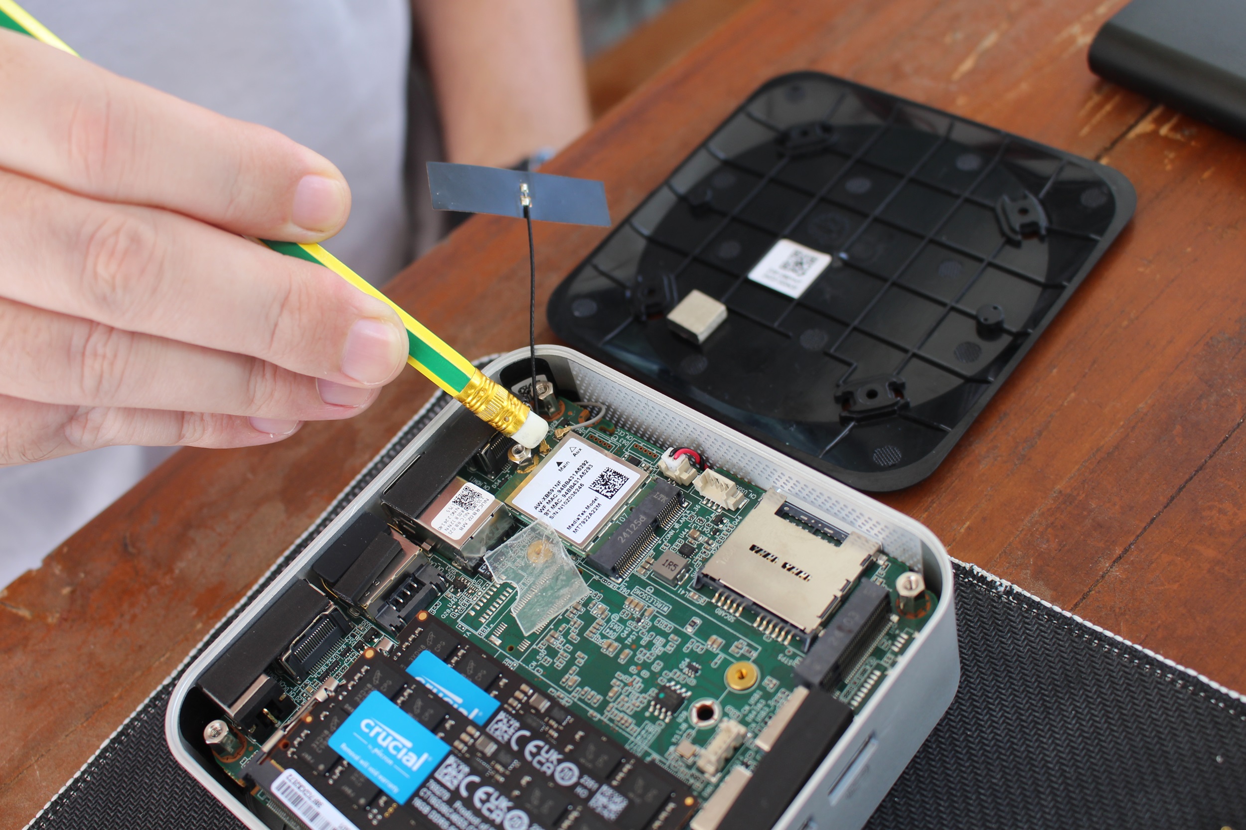
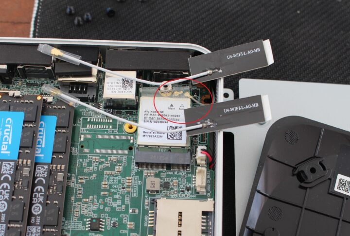
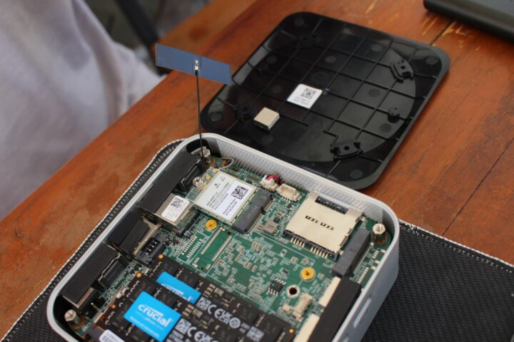
Now that we have an IPEX4 antenna, let’s install it. We’ll first need to remove the protective transparent plastic bit that covers the antenna connectors before inserting the IPEX4/MHF4 antenna using a pencil with an eraser to help push it in. We are using a pencil with an eraser because it allows us to gently insert the connector as I previously damaged a few antenna connectors using other methods (using a screwdriver to push it in).

Insert WiFi Antenna Mini PC

Now that the new antenna is installed, we can put the plastic cover back in place.

WiFi Antenna repair mini PC

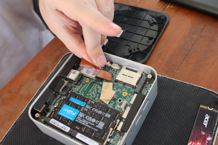
We now need to attach the antenna to the case. We won’t attach it back to the bottom cover due to the risk of breaking it again. We’ll first peel off the 3M protective film from the antenna and place it on one of the sides of the mini PC’s enclosure. Note that it works because the case is made of plastic, and if we had a metal case it could potentially block the signal.

Peel sticker on WiFi Antenna IPEX4
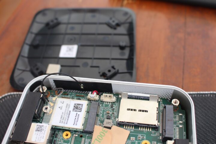
The photo below shows the new antenna attached to the side of the mini PC.

Stick WiFi Antenna GEEKOM A8 mini PC

That’s all. We fixed the GEEKOM A8 mini PC and we now have 2 antennas connected to the WiFi module for optimal wireless performance.

CNXSoft: This tutorial is a translation – with a few additional insights – of the original article on CNX Software Thailand by Suthinee Kerdkaew.

The post How to repair/replace a WiFi antenna in a mini PC appeared first on CNX Software - Embedded Systems News.
ACEBOTT QE007 review – An ESP32-based Smart Home STEAM education kit for 8+ years old kids

QE007 ESP32 Smart Home Starter Kit Review

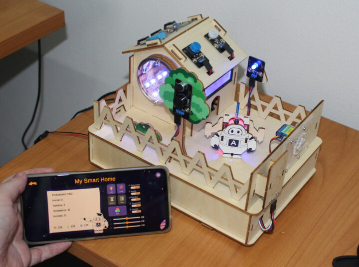
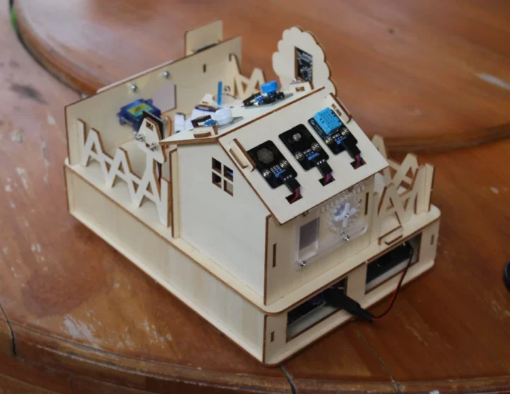
ACEBOTT QE007 ESP32-based Smart Home Starter Kit is a STEAM (Science, Technology, Engineering, Arts, and Maths) education platform that involves story reading, assembling a wooden house with various electronics sensors wired to an ESP32 board, and learning about electronics concepts (such as voltage and current) and coding with the Arduino IDE through an 18 lesson course.

ACEBOTT has various STEAM education kits, and the company sent us the QE007 “IoT Smart Home Starter Kit” for evaluation and review. So I’ll go through an unboxing, report my experience with the assembly process, and the Arduino tutorials by going through some of the eighteen lessons.

ACEBOTT QE007 unboxing

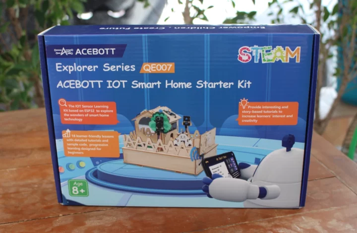
The kit comes in a nice-looking retail that reads “ACEBOTT Explorer Series QE007” and “ACEBOTT IOT Smart Home Started Kit”. The front of the package also highlights its a STEAM education kit designed for 8+ years old kids.

ACEBOTT QE007 IoT Smart Home Starter Kit

The bottom side gives the backstory and which tasks you’ll be expected to complete in order to save the world! The company also mentions you’ll need six AA batteries, but that’s optional since we can power the system with a 9V or 12V power supply.

ACEBOTT ESP32 STEAM education Smart Home kit

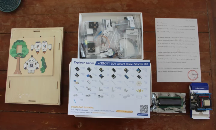
Everything is neatly packed inside with a box with the ES32 Arduino board, an LCD display, basswood cutouts, a white box with all sensor modules, screws, standoffs, and other accessories, and a letter from “Dr. Lumi”.

ACEBOTT QE007 unboxing

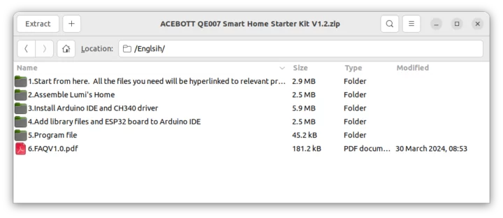
What’s missing is documentation. That’s because all documentation is available online and you can read it on your computer or print it out.

ACEBOTT QE007 kit documentation
Documentation

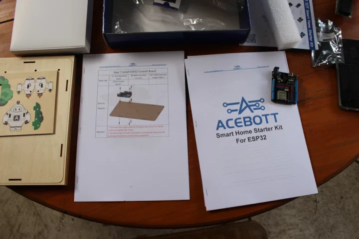
The documentation is available in English, Czech, and Russian right now. I printed the “Start from here” and “Assemble Lumi’s Home” since I don’t like reading long instructions on screens, I prefer kits with a printed manual. But that’s just a matter of personal preference.

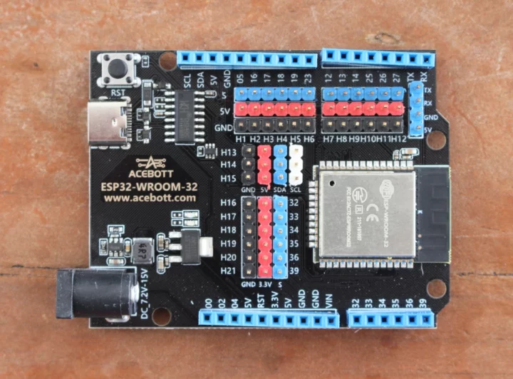
ACEBOTT ESP32 WROOM 32 Arduino board

The ACEBOTT ESP32-WROOM-32 is a typically ESP32 WiFi and BLE board with Arduino UNO form factor that takes 7.2V to 15V DC input from a DC jack, and a 5V USB port for programming (and power, but it may be enough for some sensors). The Arduino UNO headers have not been soldered in the best way (especially the header with pin 12 to Rx) on my sample, but it won’t matter with this kit since those are not used and all sensors are connected to the 3-pin and 4-pin headers in the middle of the board.

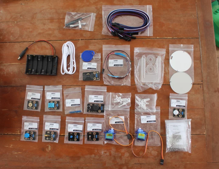
ESP32 Smart Home IoT Kit sensors accessories

It took out all items from the white box and all are properly marked for easy installation. Those include a 6AA battery holder, jumper cables, sensor modules for light, temperature, rain detection, etc…, two servo motors, a button, an RFID kit, and more.

Assembly of ACEBOTT QE007 Smart Home Starter Kit for ESP32

Now that we have opened the box and printed the manual, we can get started. It went straightaway to the assembly guide. But you may want to start reading the “ACEBOTT Smart Home Started Kit for ESP32” first with your child(ren) since it explains the background of the story with Dr. Lumi having traveled in time due to a mishap from his cat and now having to save the world by fixing the Smart Home which will magically restore the protective shield of the city and prevent an oncoming meteor from destroying everything. So serious stuff 🙂  You’ll now be acting as Dr. Luni (or his assistant) to complete various tasks to save everyone… The English grammar is not 100% perfect, but not too bad. You can download the document beforehand and read it if that’s important. The first task is to repair Dr Lumi’s house, meaning assembling the kit…

ACEBOTT Smart Home Starter Kit ESP32 User manual assembly guide

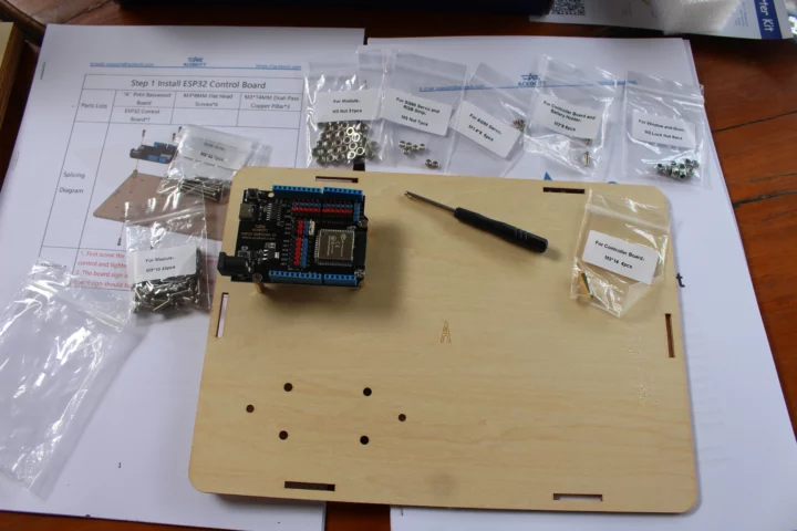
It took me around 2 hours to complete assembly, so you may want to reserve 3 to 4 hours for that part if you do that with children. No tools are needed except for the screwdriver and hex key included in the kit. Instructions are very easy to follow and we’ll start by installing the ESP32 board to the “A” basswood board. All bags with screws, nuts, and standoffs are clearly marked, and there are some spare parts, which is always appreciated. For example, if the kit requires four XYZ screws, they’ll have provided five of those. All items are neatly precut and the parts all came off easily.

ESP32 Smart Home Assembly

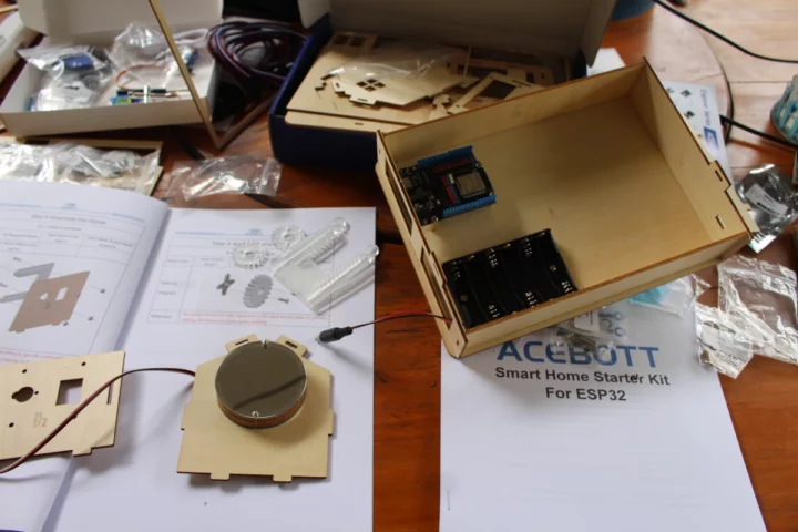
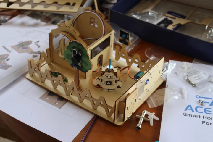
The assembly manual is 28 pages long, so I won’t show all the steps here, and report some of the steps. After having prepared the base with the ESP32 board, battery holder, and walls,  we’ll assemble the walls of the houses with accessories such as the Time Mirror with an actual mirror and an RGB LED strip inside. That part went mostly smoothly, except I had to move the strip two or three times inside the ring to make sure the cable was in the right position. It’s also important to always read the text in red as you’ll avoid many potential mistakes.

ACEBOTT Smart Home Starter Kit for ESP32 Assembly

Once the three walls are fitted with their respective modules (Time mirror, LCD, window with servo) we can install some jumper cables by making sure the black wire is also connected to the “G” pin (Ground), and then insert the walls on another basswood board.

ACEBOTT Time Mirror Light Time Machine

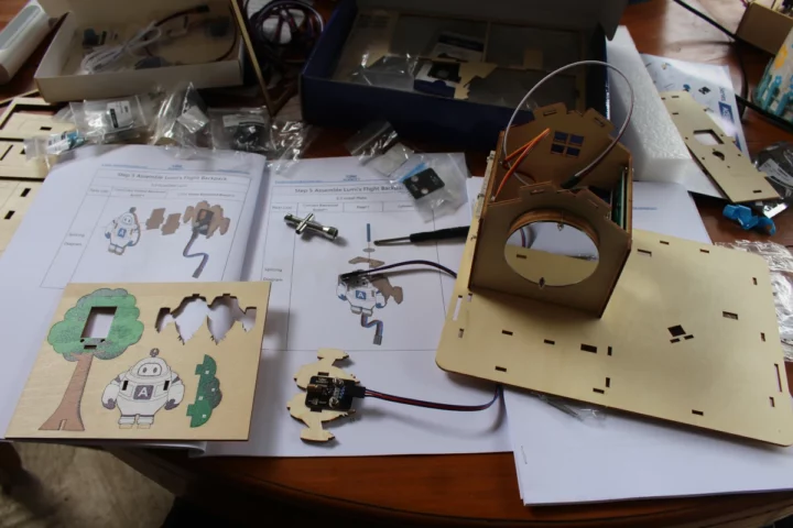
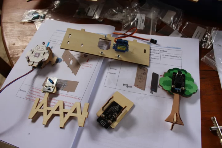
We can start assembling more accessories such as a voice module fitted to a tree, a laser module (and by that I mean Flight backpack) attached to Dr. Lumi’s space suit, some street lighting, and so on.

Smart Home STEM Kit Sensors Servo installation

Once done, it’s time to install all those accessories and put up the fences. One of these features an RFID sensor for access and an automatic door controller by the second servo. Note that the window on the house and door on the fence must be able to slide, so do not tighten the lock nuts too hard.

ACEBOTT QE007 assembly

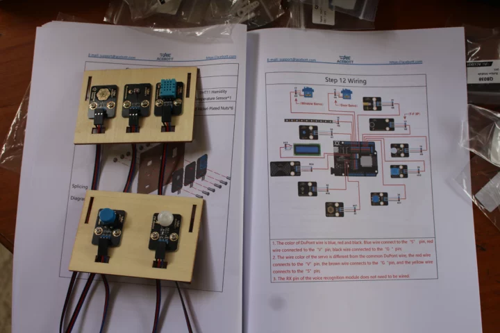
We don’t have a roof, so let’s work on that. The roof will have five modules namely a raindrop sensor, a light sensing, a DHT11 temperature and humidity sensor, a PIR motion sensor, and a button module.

ACEBOTT Smart Home Kit Roof Assembly

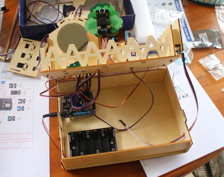
The assembly is almost complete, and it’s time to wire the house. You’ll need to pay attention here as wrong connections could potentially damage the board, so if you let your kid/student do that part by himself/herself, you’ll want to double-check before applying power. The basswood boards all have holes designed to install the jumper cables. The voice module on the three can be confusing, since it has four pins, but only requires a 3-pin cable as the Rx pin is not used.

ESP32 Arduino board modules wiring

You’ll want to install six AA batteries before completing the assembly. I didn’t do it since I’ll be powering the kit with a 9V power adapter instead. You might be able to use a 5V USB-C adapter instead, but the company says the power may not be enough for some tutorials.

ACEBOTT QE007 Review ESP32 Smart Home Starter Kit

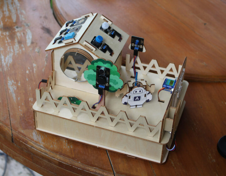
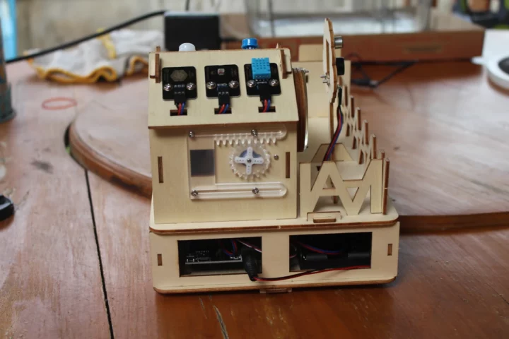
That’s the final result. It looks pretty neat if you ask me.

ACEBOTT QE007 assembly complete

Note that I’ve installed the servo gears to take photos, but this should only be done after calibration the first time an Arduino sketch with a servo is used.

ESP32 Smart House Automatic Windows

The photo above shows the battery holder powering the ESP32 board, but since I won’t be using batteries, I unplugged it and connected a 9V power supply for a quick test and see whether any smoke comes out ;).

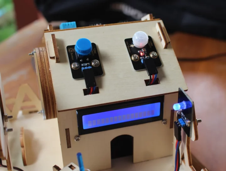
The blue light (street light) turns on and we can hear a (low volume) voice through the voice module that says “Hi, I am Lumi, welcome to my smart home”.

ACEBOTT QE007 Kit Connect Power

The PIR motion sensor is active and a red LED will light up if motion is detected, plus the display shows a row of rectangles. The latter should show on the first line, so I installed the display wrong, and I had to disassemble the roof to rotate it by 180 degrees. Nevertheless, that looks like success to me, and it was fun to assemble.

Programming the Smart Home Kit with the Arduino IDE

ACEBOOT provides 18 lessons for the kit:

  1. Repair the street lights to illuminate the yard
  2. Give the street lamp wisdom – Let the street lamp learn to breathe
  3. Save energy! Let’s add a switch to control the light
  4. Add eyes to the street lamp
  5. The Secret in the Light
  6. It’s dark and someone please light up
  7. Test whether the Shield works properly
  8. The secrets of the Time Mirror Light
  9. It’s starting to rain. Come in!
  10. The most important part of the Smart Home
  11. Make the temperature and humidity values visible
  12. The rain has stopped. Start repairing the Gate!
  13. The Guardian’s Shield has been launched
  14. Try something new
  15. A magical communication method–WIFI
  16. WIFI can also control doors and windows
  17. A new interactive control
  18. Leave a gift

I’ll test the first one (blinky sample), the Time Mirror Light, the laser demo, and “new interactive control” using an Android app connected over WiFi to control sensors, the door, the laser module, etc…

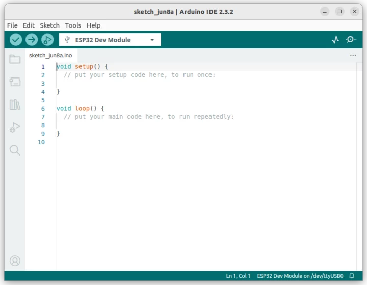
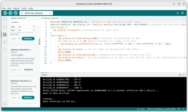
We’ll first need to install the Android IDE and ESP32 Arduino Core, then select ESP32 Dev Module, after having connected the board through its USB-C port, the COM port for the board, in my case /dev/ttyUSB0 as I’m testing the kit with Ubuntu 24.04.

ACEBOTT QE007 Arduino IDE ESP32 Dev Module

All lessons start with a story, in the case of lesson 1 we need to repair the street light, followed by an explanation of some basic concepts (current and voltage), a description of the hardware module (LED module), then one Arduino sketch, and instructions to load it to the board.

Lesson 1 tutorial extract
Extract from lesson 1

Here’s the code for the LED module which can be found in the documentation tarball with other Arduino sketches:

void setup() {// put your setup code here, to run once
  pinMode(5, OUTPUT);//set pin 5 as an output
}
void loop() {// put your main code here, to run repeatedly
  digitalWrite(5,HIGH);//let the light on
  delay(1000);//wait for one second
  digitalWrite(5,LOW);//let the light off
  delay(1000);//wait for one second
}

After we compile and upload the code to the board through the Arduino IDE the LED will flash every second.

The second demo program will test is the “Time Mirror Light”

ACEBOTT Arduino Time Mirror demo

This sketch relies on the Adafruit Neopixel library which you can install through the library manager, or maybe better for future lessons, install a bunch of libraries as explained in folder 4 of the documentation tarball.

The result does indeed look like a time travel machine…

I wanted to test the laser module, so I loaded the code for lesson 7 “Test whether the Shield works properly”:

void setup() {
  pinMode(23, OUTPUT);// set pin 23 as output for the laser
}
void loop() {
  digitalWrite(23,HIGH);// turn on the laser by setting pin 23 to a high state
  delay(5000);
  digitalWrite(23,LOW);// turn off the laser by setting pin 23 to a low state
  delay(1000);
}

It’s really basic because it only turns on the laser for 5 seconds, then turns it off for one second in an infinite loop. But the demo itself is fun because you can rotate the transparent plastic ring that is carved with tiny motifs that show on the ceiling.

ESP32 laser control

Here’s the video after turning off the room’s light.

There are lessons for each module, including one for the voice module where you can give voice commands to open/close the door or window and turn on/off the RGB LED strip, the LED, or laser. The last sample I will try is Lesson 17 as the kit will be used in the way an actual Smart Home that adults would use… We need to load an Android app to control the lights, monitor sensor, open door, etc… over WiFi.

I won’t include the full code here since it’s much longer than other samples with over 300 lines. The important part is to change the SSID and password to match your router settings before uploading the code to the board.

#include <Arduino.h>
#include <WiFi.h>
#include <ESPmDNS.h>
#include <WiFiClient.h>
String item = "0";
const char* ssid = "ACEBOTT";//change to your own WIFI name
const char* password = "1234567"; // change the WIFI password to your own
WiFiServer server(80);
volatile int wifi_mark=0,wifi_time=0;
volatile int RGB_RED=0,RGB_GREEN=0,RGB_BLUE=0;
//WIFI configuration

#include <Adafruit_NeoPixel.h>
Adafruit_NeoPixel rgb_display_16 = Adafruit_NeoPixel(10,16,NEO_GRB + NEO_KHZ800);
volatile int buttun;

Since we’ve never run a servo sketch, the servos will calibrate. You should now open the window and door fully, and install the gears. Sadly, my window servo appeared to be stuck, so I could only test the door. It’s apparently not an uncommon issue, and I tried to open the servo to fix it but was unsuccessful.

We can now download the ACEBOTT app from Google Play or the Apple Store and you’ll also find QR codes to the mobile apps on the ACEBOOT website. I installed the Android app, and we’re greeted with the following screen designed for all education kits from the company. There’s also background music in the background, which you can disable if you find it annoying.

ACEBOTT Android App

I was confused at first as I could not find the QE004 kit. That’s because there are multiple “Save The Lost City” kits, and I had to scroll down to find the QE007 kit.

ACEBOTT Android QE007 Save The Lost City

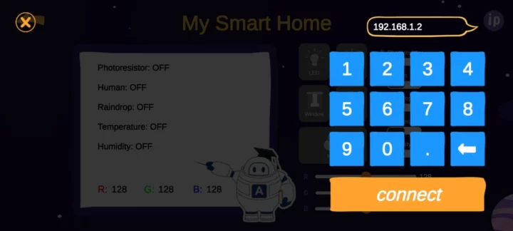
Once we enter the interface, we need to tap on the IP icon in the top right corner to enter the IP address of the ESP32 board. It can be found in the serial monitor, as somehow the LCD is not used, and shows some old values from a previous sketch (Temperature and Humidity data in my case).

My Smart Home Set IP Address

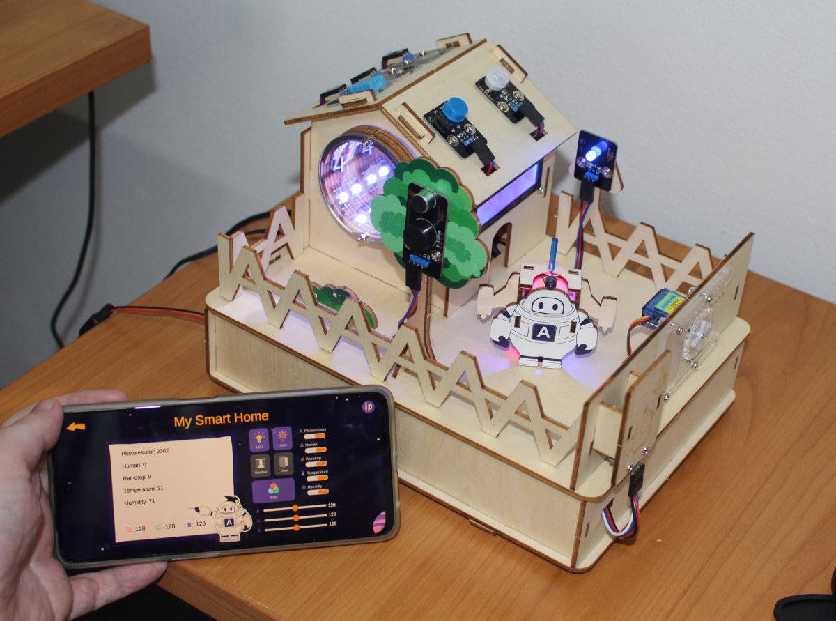
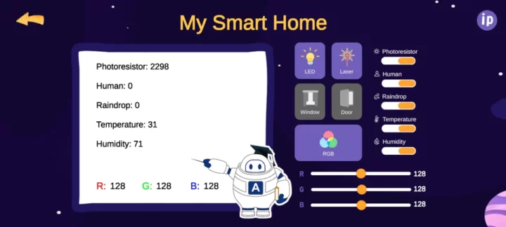
But once we press connect, you should be greeted by a “Connected” message, and then you can turn on the LED, the RGB strip in the Time Mirror, the laser, and all the roof sensors to read the value in the app. I could also close and open the door, although it’s not always operating smoothly. I further tighened the screws and nuts holding the servo, and it was better.

ACEBOTT Android QE007 WiFi control

QE007 ESP32 Smart Home Starter Kit Review

Watch the short demo below to see the ACEBOTT app and the QE007 Smart Home kit in action.

Conclusion

Overall I’m pretty happy with the ACEBOTT QE007 Smart Home Starter Kit as it is a fun STEAM education to play with thanks to an interesting background story making the user the hero to save the world, a rather challenging and entertaining assembly, and eighteen lessons from easy (blinky) up to more complex IoT solution (Android app for remote management) where student learn electronics theory and Arduino coding.

A few things that could be improved include the door/window mechanism as it takes time to fine-tune it to work reasonably well, the voice module’s volume is rather low, and the tutorials may benefit from editing by a translation company with native speakers. Don’t get me wrong, the textbook is perfectly understandable, and I’m only saying this considering it’s going to be read by children who are in the process of learning English.

The price is also right as the ACEBOTT QE007 kit selling for $67 plus shipping while offering many hours of learning experience. CNX Software readers can also get a 10% discount with the coupon code CNX10 valid until July 5, 2024.

The post ACEBOTT QE007 review – An ESP32-based Smart Home STEAM education kit for 8+ years old kids appeared first on CNX Software - Embedded Systems News.
UP Xtreme i14 SBC offers Intel Core Ultra 5/7 Meteor Lake SoC, up to 64GB LPDDR5 for robotics and AIoT applications

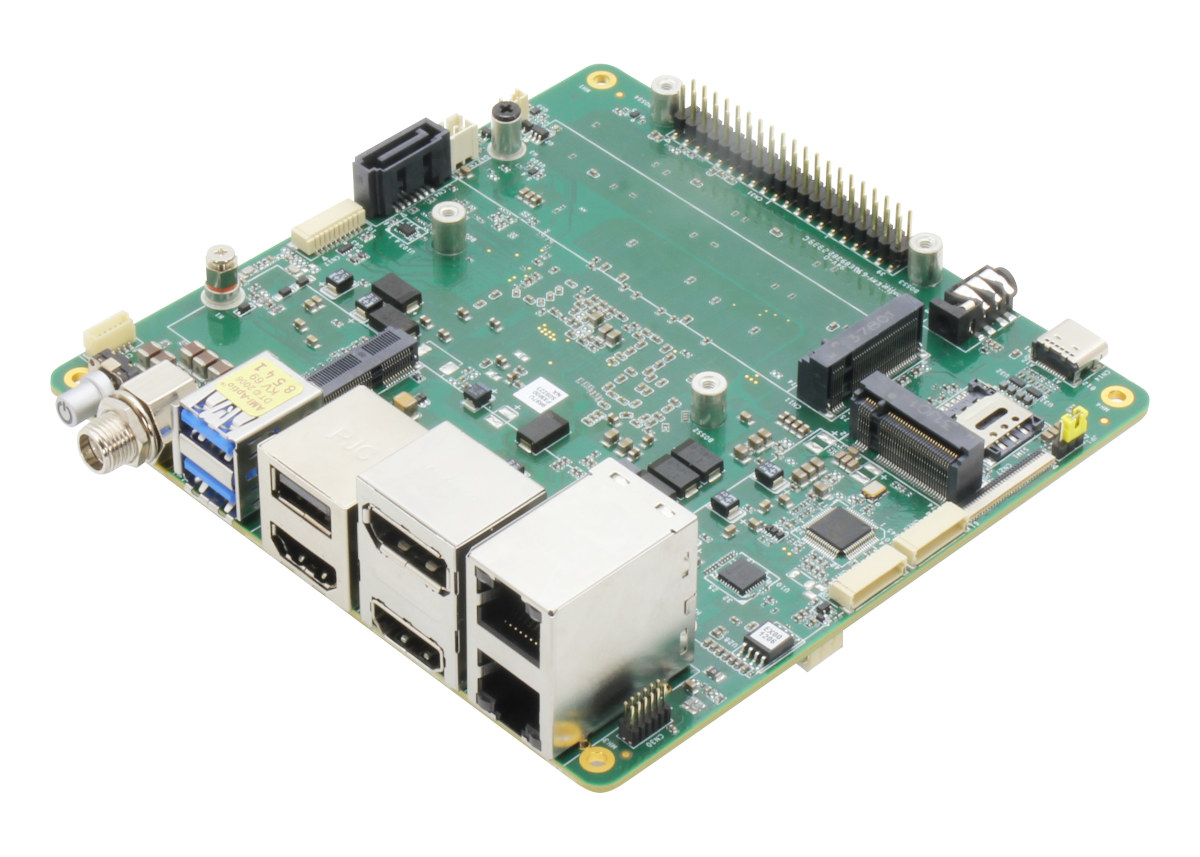
UP Xtreme i14 Core Ultra 5 SBC

AAEON has launched the UP Xtreme i14 SBC based on a choice of Intel Core Ultra 5/7 Meteor Lake SoCs, up to 64GB LPDDR5, M.2 PCIe sockets and a SATA port for storage, 2.5GbE and GbE interfaces, four 8K capable video output ports (HDMI, DP, and USB-C), a MIPI CSI camera interface, and more.

The 14th Intel Core Ultra 5/7 SoC features up to 16 cores, Intel Arc graphics, and an Intel AI Boost NPU that deliver up to 32 TOPS combined and make the UP Xtreme i14 board especially suitable for applications such as Autonomous Mobile Robots (AMR), Smart Retail, and AI-assisted healthcare imaging.

UP Xtreme i14 Core Ultra 5 SBC

UP Xtreme i14 specifications:

  • Meteor Lake-H/U SoC (one of the other)
    • Intel Core Ultra 7  165H 16-core (6P+8E+2LPE) processor @ 1.4 / 5.0 GHz with 24MB cache, Intel 8Xe LPG graphics @ 2.3 GHz, Intel AI Boost NPU; TDP: 28W
    • Intel Core Ultra 7 155H 16-core (6P+8E+2LPE) processor @ 1.4 / 4.8 GHz with 24MB cache, Intel 8Xe LPG graphics @ 2.25 GHz, Intel AI Boost NPU; TDP: 28W
    • Intel Core Ultra 5 135H 14-core (4P+8E+2LPE) processor @ 1.7 / 4.6 GHz with 18MB cache, Intel 8Xe LPG graphics @ 2.2 GHz, Intel AI Boost NPU; TDP: 28W
    • Intel Core Ultra 5 125H 14-core (4P+8E+2LPE) processor @ 1.2 / 4.9 GHz with 18MB cache, Intel 7Xe LPG graphics @ 2.2 GHz, Intel AI Boost NPU; TDP: 28W
    • Intel Core Ultra 7 165U 12-core (2P+8E+2LPE) processor @ 1.7 / 4.9  GHz with 12MB cache, Intel 4Xe LPG graphics @ 2.0 GHz, Intel AI Boost NPU; TDP: 15W
    • Intel Core Ultra 7 155U 12-core (2P+8E+2LPE) processor @ 1.7 / 4.8 GHz with 12MB cache, Intel 4Xe LPG graphics @ 1.95 GHz, Intel AI Boost NPU; TDP: 15W
    • Intel Core Ultra 5 135U 12-core (2P+8E+2LPE) processor @ 1.6 / 4.4 GHz with 12MB cache, Intel 4Xe LPG graphics @ 1.9 GHz, Intel AI Boost NPU; TDP: 15W
    • Intel Core Ultra 5 125U 12-core (2P+8E+2LPE) processor @ 1.3 / 4.3 GHz with 12MB cache, Intel 4Xe LPG graphics @ 1.85 GHz, Intel AI Boost NPU; TDP: 15W
    • All model features Intel Arc graphics with AV1 encode/decode, H.265 (HEVC) 8-bit codec, DX 12.1, OpenGL 4.6, oneAPI
  • System Memory – Up to 64GB onboard LPDDR5 (dual-channel)
  • Storage
    • 2x M.2 2280 M-Key sockets for NVMe SSDs
    • 1x SATA III 6Gb/s port
  • Video Output
    • 2x HDMI 2.1 ports up to 8Kp60
    • 1x DisplayPort (DP) 2.1 up to 8Kp60
    • DP 1.4 via USB Type-C port up to 8K60
  • Audio – 3.5mm audio (Mic-in+Line-out) jack; digital audio via HDMI and DisplayPort
  • Camera – MIPI-CSI via FPC connector
  • Networking
    • 2.5GbE port via Intel I226-IT controller
    • Gigabit Ethernet RJ45 port via Intel I219 controller
    • Optional WiFi and Bluetooth via M.2 E-Key socket
    • Optional 4G LTE/5G via M.2 B-Key socket and Nano SIM card slot
  • USB
    • 2x USB 3.2 Gen 2 Type-A ports
    • USB 3.2 Gen 2 Type-C port
    • USB 2.0 Type-A port
    • 2x USB 2.0 interfaces via 10-pin header
  • Serial – 2x RS-232/422/485 via 10-pin header
  • Expansion
    • 40-pin GPIO header
    • M.2 2230 E-Key socket (PCIe Gen 3 [x1], USB 2.0)
    • 2x M.2 2280 M-Key sockets (PCIe Gen 4 [x4])
    • M.2 3052 B-Key socket (PCIe Gen 3 [x1], USB 3.2 Gen 2 [x1]) coupled with Nano SIM slot (USB 3.0)
  • Security – Onboard TPM 2.0
  • Misc – Power button, RTC, front panel header
  • Power Supply – 9-36V DC-in (Lockable plug); AT/ATX (ATX as default)
  • Power Consumption – TBD
  • Dimensions – 122.5 x 120.35mm
  • Weight – 360 grams
  • Temperature Range – 0°C ~ 60°C, 0.5m/s airflow (with cooler)
  • Humidity – 0% ~ 90% relative humidity, non-condensing
  • Certifications – CE/FCC Class A, RoHS Compliant, REACH

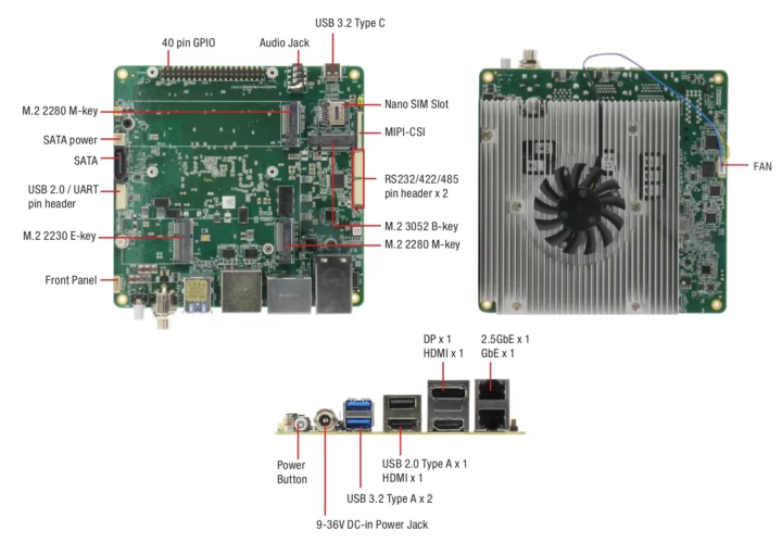
UP Xtreme i14 SBC ports description

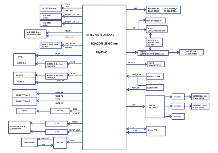
Intel Meteor Lake SBC block diagram
Block diagram

AAEON provides support for Windows 10/11 64-bit and Ubuntu 22.04 with Linux 6.5 and greater. The company also says it has “instituted power limitations via CPU frequency scaling to maintain the stability of the board’s CPU temperature and voltage during operation”, but I don’t see how it differs from all other recent Intel systems. You’ll find resources to get started on the Wiki which also mentions support for the Yocto Project.

The UP Xtreme i14 is not the first 14th Intel Meteor Lake board or computer-on-module we’ve covered and some other products include the ADLINK cExpress-MTL COM Express Type 6 Compact module, ASRock Industrial NUC Ultra 100 motherboard, and DFI MTH968 COM Express module. But as a community board, the UP Xtreme i14 will be easier to source by individual and small companies.

The UP Xtreme i14 is now available for pre-order via the UP shop with the Intel Core Ultra 5 processor SKU selling for $749 with 16GB RAM, and the Intel Core Ultra 7 processor SKU going for $959. A 19V/6.32A is offered for free during the pre-order period until July 5, but you’ll still need to add storage and other accessories. A full system with an enclosure called the UP Xtreme i14 Edge is also in the works, but not yet available. Additional information may also be found on the product page.

The post UP Xtreme i14 SBC offers Intel Core Ultra 5/7 Meteor Lake SoC, up to 64GB LPDDR5 for robotics and AIoT applications appeared first on CNX Software - Embedded Systems News.
Fibocom FG370 dual-band WiFi 7 and 5G cellular module targets 5G FWA routers

Fibocom FG730 WiFi 7 5G Cellular module

Fibocom FG370 is a compact module that combines WiFi 7 and 5G cellular connectivity designed for 5G FWA routers for the home, SMB (Small and Medium-sized Business), and industrial applications.

Based on the MediaTek T830 quad-core Arm Cortex-A55 SoC, the FG370 supports 5G NR sub-6GHz, two 10Gbps USXGMII interfaces, and dual-band BE7200 WiFi 7 achieving an MLO (Multi-link operation) speed of up to 7.2Gbps.

Fibocom FG730 WiFi 7 5G Cellular module

Note this is not the first “FG370 announcement” from the company, as global operators have used the 5G-only FG370 since October 2023, and the company introduced the FG370 with 5G and tri-band BE19000 WiFi 7 at MWC2024. The company has unveiled a mid-range variant of the FG370 module with 5G and BE7200 at Computex 2024.

The company has yet to release a datasheet for the 5G + WiFi 7 variants, but for reference, here are the Fibocom FG370 (5G-only) specifications: (North American version)

  • SoC – MediaTek T830 quad-core Cortex-A55 processor up to 2.2 GHz with network accelerators, MediaTek M80 5G modem (3GPP Rel 16)
  • System Memory – 2GB DDR
  • Storage – 4GB flash
  • Cellular connectivity
    • Support SA/NSA, NR CA
    • Frequency bands
      • 5G Sub-6 – n2/5/7/12/14/25/26/29/30/38/41/48/66/70/71/77/78
      • LTE FDD – B2/4/5/7/12/13/14/17/25/26/29/30/66/71
      • LTE TDD –  B38/41/42/43/48
    • MIMO (LB 4×4 MIMO)
      • 5G NR: DL 4×4 MIMO; UL 2×2 MIMO:
      • LTE – DL 4×4 MIMO
    • 8Rx / 3Tx reserved
    • Downlink
      • 5G NR Sub-6: 256QAM / Peak data rate 7.01Gbps
      • 4G LTE: 256QAM / Peak Rate 1.6Gbps
    • Uplink
      • 5G NR Sub-6: 256QAM / Peak data rate 1.25Gbps
      • 4G LTE: 256QAM / Peak Rate 211Mbps
  • GNSS – GPS/GLONASS/Beidou/Galileo/QZSS
  • Antennas – 8x cellular + 1x GNSS
  • Host communication – AT Command Set: 3GPP TS 27.007 and 27.005, proprietary FIBOCOM AT commands
  • Interfaces – UART, PCIe 4.0, GPIO, I2S, UIM
  • Operating Voltage –  3.3V to 4.4V; typical 3.8V
  • Dimensions – 48 x 45 x 2.75mm (LGA package)
  • Temperature Range – Standard: -30 to +75°C;  extended: -40 to +85°C
  • FCC certifications (NA version)

Drivers are available for Linux 5.4 and the module is supposed to run OpenWrt 21.02. While the model above only supports 5G, we do have some information about the just announced WiFi 7 dual-band model from the press release which looks to be based on the MediaTek Filogic 860 chipset:

  • IEEE 802.11be (Wi-Fi 7) standard
  • 4K QAM (Quadrature Amplitude Modulation) modulation scheme
  • 160MHz channel bandwidth
  • Dual-band 2.4GHz 4×4 and 5GHz 5×5 to achieve multi-link speed of up to 7.2Gbps.
  • Features – OFDMA, Multi-RU, and MU-MIMO
  • 5dB antenna gains

5G + WiFi 7 solutions

Potential applications for the 5G FWA routers based on the FG370 include 4K/8K video transmission, virtual/augmented reality, cloud gaming, video conferencing, etc… As discussed above there’s limited information about the 5G + WiFi 7 modules, but any details should eventually surface on the FG370 product page.

Thanks to TLS for the tip.

The post Fibocom FG370 dual-band WiFi 7 and 5G cellular module targets 5G FWA routers appeared first on CNX Software - Embedded Systems News.
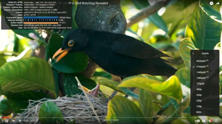
The S5 Trekker is a compact Meshtastic communication device for hikers and preppers

s5 minitrekker trekker

The S5 Trekker Bravo and the S5 Trekker Mini are two Meshtastic-enabled radios designed by SpecFive LLC, a team of engineers based in the United States.

s5 minitrekker trekker
S5 Trekker and MiniTrekker

Both devices are based on the Heltec Wireless Tracker from Heltec Automation. The Wireless Tracker integrates Espressif’s ESP32-S3 system-on-a-chip, a 160 x 80 TFT LCD, a SemTech SX1262 LoRa chip, and a Unicore UC6580 GNSS chip.

The MiniTrekker is much lighter than the Trekker Bravo and features a built-in attachment hook for connecting it with other gear. Both radios are built to be durable enough to resist the rigors of outdoor exploration. They come pre-flashed with the open-source Meshtastic software and are ready to be used out of the box.

The S5 Trekkers are intended to be used when hiking, trekking, and partaking in other outdoor activities that take one away off the well-trodden path. It is also useful for setting up a reliable communication network in the event of emergencies.

We have covered similar solutions for outdoor enthusiasts such as the Trekko Pico, TTGO T-Beam, and TTGO LoRa32.

S5 Trekker specifications:

  • Development Board – Heltec Wireless Tracker, with
  • LoRa Frequency – 915 MHz
  • Antenna –  915 Mhz LoRa antenna / GPS Ceramic antenna
  • Urban Range – ~1.6 to 4.8 km
  • Rural Range – ~4.8 to 8 km
  • USB – USB-C port for charging
  • Battery
    • 18650 Li-ion battery (Bravo), 1200mAh LiPo Battery (MiniTrekker)
    • Battery Life
      • Bravo: 8 hrs active / 24 hrs standby
      • MiniTrekker: 3 hrs active / 6 hrs standby
  • Dimensions – 140 x 50 x 40 mm (Bravo), 83 x 39 x 20 (MiniTrekker)
  • Weight –  165 g (Bravo), 64g (MiniTrekker)
  • Case Material – PETG
S5 MiniTrekker
S5 MiniTrekker

The MiniTrekker is also configured to work with the Android Team Awareness Kit (ATAK) software. You will need to install the ATAK and Meshtastic apps on your phone and set them up to work with the MiniTrekker.

The S5 MiniTrekker and the S5 Trekker Bravo are priced at about $99 and $119 respectively on the Tindie store.

The post The S5 Trekker is a compact Meshtastic communication device for hikers and preppers appeared first on CNX Software - Embedded Systems News.
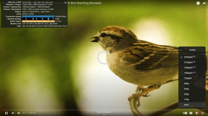
PiWings 2.0 is a tiny drone based on Raspberry Pi Pico and ESP8266 WiFi module (Crowdfunding)

PiWings 2.0 Raspberry Pi Pico drone variants

SB Components’ PiWings 2.0 is a small drone combining a Raspberry Pi Pico with an ESP8266 WiFi module (ESP-12E) for wireless connectivity, and designed for STEM education and drone enthusiasts.

The PiWings 2.0 board supports up to six motors and four servos, includes a 6-axis IMU for auto-leveling, and features I2C, SPI, UART, and GPIO expansion ports for custom sensor and/or actuator support. The drone itself is offered with three, four, or six rotors.

PiWings 2.0 Raspberry Pi Pico drone variants
PiWings 2.0 boards and three drone variants

PiWings 2.0 key features and specifications:

  • Microcontroller board – Raspberry Pi Pico with Raspberry Pi RP2040 dual-core Cortex-M0+ microcontroller, 264KB SRAM
  • Wireless module – ESP-12E (ESP8266) WiFi module for iBus support
  • Motor Drivers – 6 channels (3A DC)
  • Servo Motors – 4 channels
  • USB – 1x micro USB port (on Raspberry Pi Pico)
  • Expansion – I2C, SPI, UART, GPIO ports
  • Sensor – On-board 6-axis IMU (MPU6050) for auto-leveling
  • Misc – 4x RGB LEDs
  • Power Supply
    • 3V – 5.5V DC (1S LiPo / 1S LiIon / 3S NiMh)
    • Reverse supply protection
  • Dimensions – TBD
PiWings 2.0 drone ESP8266
Blurry photo courtesy of SB Components showing the board with ESP8266 module

SB Components say they have developed an RP2040 SDK on Visual Studio and the Arduino IDE, with the API enabling a “simple programming style and basic math concepts” suitable for kids. They’ll also provide sample codes, but as usual, they won’t release anything until after shipping rewards. There’s also some gibberish about the drone being ideal for STEM education but nothing to show for it… The drone is controlled by an Android app (see video embedded below), but I could not identify it.

We’ve already seen it’s perfectly possible to create a drone with an ESP32 (or a Raspberry Pi Pico W), so the dual MCU design choice for the PiWings 2.0 may seem odd, and the company did not explain this choice. It’s often just a question of software support and the existing FlySky iBus Decoder Arduino library for the ESP8266 may explain it.

SB Components has launched the PiWings 2.0 on Kickstarter with a 10,000 GBP target that has already been surpassed. Rewards start at $141 for the tri-copter, $160 for a quad-copter, and $178 for the hexa-copter. These prices appear to include worldwide shipping, and backers should receive their perks sometime in September.  For reference, you can get a similar-looking, albeit smaller, ESP32 quadcopter on Aliexpress for about $44 shipped (but the battery needs to be purchased separately).

The post PiWings 2.0 is a tiny drone based on Raspberry Pi Pico and ESP8266 WiFi module (Crowdfunding) appeared first on CNX Software - Embedded Systems News.
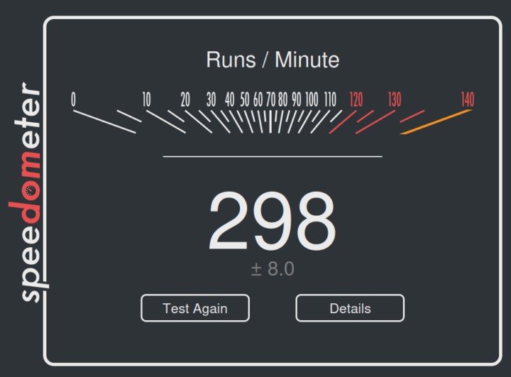
Orange Pi 3B V2.1 SBC has been revamped with better WiFi 5 connectivity, M.2 2280 NVMe/SATA SSD socket

Orange Pi 3B V2.1

Shenzhen Xunlong Software has introduced the Orange Pi 3B V2.1 SBC with an M.2 socket that supports 2280 NVMe or SATA SSDs, and a new Ampak AP6256 WiFi 5 and Bluetooth 5 wireless module replacing the Allwinner AW859A-based CDTech 20U5622 module in the first revision of the board.

The Orange Pi 3B SBC was first introduced in August 2023 as a Rockchip RK3566 SBC with Raspberry Pi 3B form factor and support for M.2 2230 and 2242 NVMe or SATA storage. The new Orange Pi 3B V2.1 supports longer M.2 2280 SSDs at the cost of being slightly bigger than a credit card (89×56 mm) and offers better WiFi 5 connectivity.

Orange Pi 3B V2.1

Orange Pi 3B V2.1 specifications:

  • SoC – Rockchip RK3566
    • CPU – Quad-core Cortex-A55 processor @ up to 1.8 GHz
    • GPU – Arm Mali-G52 2EE GPU with support for OpenGL ES 1.1/2.0/3.2, OpenCL 2.0, Vulkan 1.1
    • NPU – 0.8 TOPS AI accelerator with support for Caffe, TensorFlow, TFLite, ONNX, PyTorch, Keras, Darknet
    • VPU
      • 4Kp60 H.265, H.264, VP9 video decoding
      • 1080p100 H.265 video encoding
      • 1080p60 H.264 video encoding
    • Process – 22nm
  • System Memory – 2GB, 4GB, or 8GB LPDDR4/4x
  • Storage
    • eMMC module socket (16GB, 32GB, 64GB, 128GB, or 256GB capacity)
    • 16MB or 32MB SPI flash
    • M.2 M-Key socket for SATA III or PCIe 2.0 2280 NVMe SSD
    • MicroSD card slot
  • Video Output
    • HDMI 2.0 port up to 4Kp60
    • 2-lane MIPI DSI connector
    • eDP 1.3 connector
  • Camera I/F – 2-lane MIPI CSI connector
  • Audio – 3.5mm headphone jack, digital audio output via HDMI
  • Networking
    • Gigabit Ethernet RJ45 port via YT8531C transceiver
    • Dual-band WiFi 5 and Bluetooth 5.0 via Ampak AP6256 wireless module
  • USB
    • 1x USB 3.0 host port
    • 2x USB 2.0 host ports
    • 1x USB 2.0 Device/Host port
  • Expansion – 40-pin Raspberry Pi compatible GPIO header with up to 28x GPIOs, UART, SPI, I2C, PWM
  • Misc
    • MaskROM key, Reset key, Power key
    • 2-pin 5V fan connector
    • 2-pin RTC battery connector
  • Power Supply
    • 5V/3A via USB Type-C port
    • Rockchip RK809-5 PMIC
  • Dimensions – 89 x 56 mm
  • Weight – 52 grams

Orange Pi 3B V2.1 Bottom M.2 2280 socket, eDP, microSD card

Shenzhen Xunlong Software says the board supports Android 11, Ubuntu 22.04, Ubuntu 20.04, Debian 11, Debian 12, OpenHarmony 4.0 Beta1, Orange Pi OS (Arch), Orange Pi OS (OH) based on OpenHarmony, and other operating systems. You’ll find all those on the Download page, but as usual, the devil is in the details, and it’s unclear what is supported and what is not in each image. The Orange Pi 3B is also supported in Armbian with community-maintained Debian and Ubuntu images.

Rockchip RK3566 SBC M.2 2280 socket
M.2 2280 NVMe SSD connected to Orange Pi 3B

The new Orange Pi 3B V2.1 can be purchased on Amazon for $40.99 and up, as well as on Aliexpress for $30 and up with the final price depending on the selected configuration, shipping, and eventual taxes.

The post Orange Pi 3B V2.1 SBC has been revamped with better WiFi 5 connectivity, M.2 2280 NVMe/SATA SSD socket appeared first on CNX Software - Embedded Systems News.
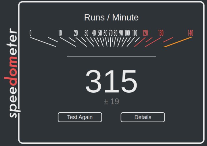
NiCE5340 SoM packs Nordic nRF5340 MCU, Lattice iCE40 FPGA, and 11 sensors into a tiny 29x16mm form factor

Stefano Viola's NiCE5340 SoM

Stefano Viola’s NiCE5340 SoM is built around a Nordic Semi nRF5340 Bluetooth SoC, an iCE40 FPGA, 11 sensors, a battery charger, and various other peripherals in a 29×16 mm form factor. The nRF5340 used in the SoM is a low-power, dual-core Arm Cortex-M33 SoC with Bluetooth 5.4, Bluetooth LE (BLE), Thread, Zigbee, and other proprietary protocols. Meanwhile, the Lattice iCE40 FPGA features 3520 logic cells, 80 Kbits of embedded Block RAM, I2C, and SPI blocks, and many other features that make it suitable for applications like environmental monitoring, health tracking, and others.

Previously, we have written about Unexpected Maker NANOS3, TinyS3, FeatherS3, and ProS3 boards, and ESP32-S3 4G dev board which all fall under the tiny and compact board category but this is the first time we have seen an MCU board with so many features built into a module of that size.

NiCE5340 SoM with nRF5340 SoC and iCE40 FPGA

Stefano Viola’s NiCE5340 SoM Specification

  • ICs
  • Storage – 64Mbit (8MB) flash (AT25QL641-UUE-T)
  • Wireless Connectivity
    • Bluetooth 5.4 LE (BLE)
    • Thread
    • Zigbee
  • Sensors
    • 6DOF IMU – LSM6DSMTR (STMicroelectronics)
    • Biosignal converting unit – AS7057-BWL (Osram)
    • Magnetometer – MMC3630KJ (Memsic)
    • SAR sensor (touch) – SX9328ICSTRT (Semtech)
    • PDM MEMS MIC – ICS-41351 (TDK)
    • Humidity/temperature – SHTC3 (Sensirion)
    • Haptic driver – DRV2605LYZF (Texas Instruments)
    • RGB IR color sensor – BH1749NUC-E2 (Rohm Semi)
    • Barometric pressure sensor – DPS310XTSA1 (Infineon)
    • Charge/discharge current measurement – INA231AIYFDT (Texas Instruments)
  • Misc – RTC – MAX31342EWA+T (Analog Devices)
  • Power Management – Nordic Semiconductor nPM1100
  • Additional Features:
    • Onboard chip antenna
    • MHF4 connector for external antenna
    • RGB LED (Only the R and G connected)
  • Dimensions – 29 x 16 millimeters

NiCE5340 Block Diagram

After a careful inspection, I immediately noticed that there was no way to program this board so after looking at the schematic of the board I found that there is a separate carrier board for the SoM, and there, the USB port is directly connected to the nRF5340 IC, and the SoC is connected to the FPGA via I2C and QSPI bus. As the nRF5340 is a wireless IC, Viola mentioned that it can also support Over-the-air (OTA) programming but OTA for the FPGA is still in the testing phase.

NiCE5340 Top and Bottom

Upon checking I found the design of the SOM is quite unique and annoying at the same time, The SoM will not feature a connector like Raspberry Pi CM4 or a SODIMM connector like the Late Panda Mu, but the SoM has land-grid-array (LGA)-style pads which need to be reballed and then soldered to the carrier board.

1714588180576

Stefano Viola designed the NiCE5340 board primarily as a design challenge, so its future isn’t set in stone. You can find the PDF schematic and nRF5340 firmware on GitHub, and Viola plans to add code examples for the Arm MCU and iCE40 FPGA soon. If you’re interested in this board, want to try it out, or have ideas for improvements, connect with Stefano Viola on LinkedIn.

by Hackster.io

The post NiCE5340 SoM packs Nordic nRF5340 MCU, Lattice iCE40 FPGA, and 11 sensors into a tiny 29x16mm form factor appeared first on CNX Software - Embedded Systems News.
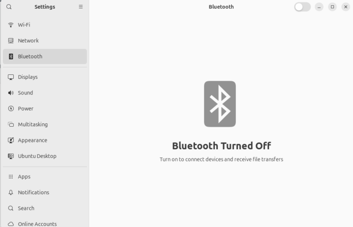
Beelink EQ13 is an Intel N200 or N100 mini PC with an integrated power supply

Beelink EQ13 mini PC built in power supply

Beelink EQ13 is yet another Alder Lake-N mini PC, but it is offered with either the Intel Processor N100 or the less common Processor N200 CPU and integrates a power supply making it more portable as the user just needs to carry a power cord in his/her bag besides the device itself.

The Beelink EQ13 ships with 16GB DDR5 and a 500GB NVMe SSD. It’s an evolution of the earlier N100-based Beelink EQ12 but with a different port arrangement and slightly larger design due to the internal power supply. It still comes with two Ethernet ports, dual HDMI 2.0, an audio jack, three USB 3.0 Type-A ports, and a USB-C port with DisplayPort Alt mode. An extra USB 2.0 port has been added to the rear panel.

Beelink EQ13 mini PC built in power supply

Beelink EQ13 specifications (with highlights in bold and strikethrough showing differences against the Beelink EQ12)

  • Alder Lake-N SoC (one or the other)
    • Intel Processor N100 quad-core processor @ up to 3.4 GHz (Turbo) with 6MB cache, 24 EU Intel HD graphics @ up to 750 MHz; TDP: 6W
    • Intel Processor N200 quad-core processor @ up to 3.7 GHz (Turbo) with 6MB cache, 32EU Intel HD graphics @ up to 750 MHz; TDP: 6W (Configurable up to 25W TDP according to Beelink)
  • System Memory – 16GB DDR5 4800 MHz SO-DIMM module
  • Storage
    • 500GB M.2 2280 NVMe (PCIe Gen 3 x4) SSD upgradeable up to 2TB
    • Additional M.2 2280 NVMe (PCIe Gen 3 x1) SSD socket
    • 2.5-inch SATA drive bay
    • MicroSD card slot
  • Video Output
    • 2x HDMI 2.0 up to 4Kp60
    • 1x DisplayPort up to 4Kp60 via USB-C port
    • Up to three independent displays support
  • Audio – 3.5mm audio jack, digital audio via HDMI and DP
  • Networking
    • 2x 2.5GbE Gigabit Ethernet RJ45 ports
    • Dual-band WiFi 6 (up to 600 Mbps) and Bluetooth 5.2 AX101 module
  • USB
    • 3x USB 3.2 10Gbps ports
    • 1x USB 3.2 Type-C 10Gbps port with DisplayPort Alt. mode
    • 1x USB 2.0 port
  • Misc
    • Power button, Power LED
    • Clear CMOS pinhole
    • BIOS with support for WoL and auto power on
    • “Silent” fan, heat fins, and heat pipe for cooling
    • Dust filter
  • Power Supply – Built-in 100-240V 50/60Hz power supply with 19V/4.47A output (85 Watts PSU)
  • Dimensions – 12.6 x 12.6 x 3.9 cm
  • Weight – TBD
  • Temperature Range – Operating: -10 to 45°C; storage: -20 to 60°C
  • Humidity – Operating: 30% to85%; storage: 10% to 90%

Beelink EQ13 portsThe Beelink EQ13 ships with Windows 11 Pro preinstalled, a 1-meter HDMI cable, a power cord (that looks to be 1m to 1.5m long, nothing like in the first photo), and a user manual.

Most quad-core Alder Lake-N processors have similar performance as we’ve seen in our Intel N95 vs N97 vs N100 comparison, although the N97 is ahead when it comes to 3D graphics, and I’m not sure the Processor N200 has much to offer over its peers in terms of performance.  The performance of the 500GB MVMe SSD may have more impact on the overall user experience than the choice of quad-core Alder Lake-N processor. Beelink may be able to extract more performance with a 25W TDP in a way similar to the “Unlimited Performance” in the ODROID-H4 Plus SBC, but we don’t have any confirmation yet since the company did not expand on this subject.

Intel Processor N200 mini PC internal structure
Beelink EQ13 Internal design

All of the photos above come from the MINIX PC store where the system is sold for $250 and up (3% off with coupon code CNXSOFT),  but you’ll also find the Beelink EQ13 mini PC on Amazon for $259 (N100) and $299 (N200). Please ignore user feedback on the Amazon links, because Beelink thought it was a good idea to reuse a page for an older model, so none of the reviews are for the new EQ13.

Via Liliputing and MiniMachines

The post Beelink EQ13 is an Intel N200 or N100 mini PC with an integrated power supply appeared first on CNX Software - Embedded Systems News.
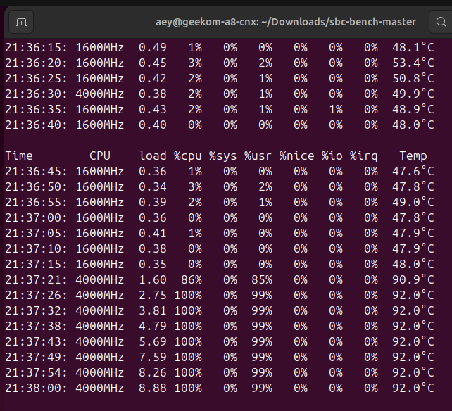
PicoQuake USB vibration sensor is based on the RP2040 MCU and the ICM-42688-P vibration sensor

picoquake usb vibration sensor

The PicoQuake is a USB vibration sensor with a MEMS accelerometer covering a wide range of vibrations. It is capable of capturing vibrations in the low-frequency range (tall buildings, bridges) to the high-frequency range (motors, industrial machinery). It can operate as a standalone device and connect to a computer via a USB cable.

picoquake usb vibration sensor

Furthermore, it is based on the Raspberry Pi RP2040 microcontroller and uses a low-noise MEMS inertial measurement unit, the TDK InvenSense ICM-42688-P, which combines a 3-axis gyroscope and a 3-axis accelerometer. The low-noise IMU sensor used enables the PicoQuake to profile vibrations of very low magnitude.

The PicoQuake sensor is a product from Slovenian maker, PLab, just like the FOCn driver module we took a look at recently. Potential use cases for the PicoQuake include optimizing brushless DC motor vibrations (important in small mobility products such as electric bikes and scooters), tracking trackpad clicks, smart home automation, and predictive maintenance.

We have previously covered other vibration sensors such as the Raspberry SHAKE HAT, Exo Sense Pi multi-sensor device, and the CN0549 CBM development board.

PicoQuake specifications:

  • Microcontroller – Raspberry Pi RP2040 dual-core Cortex-M0+ MCU @ 133 MHz with 264 KB SRAM
  • Storage – Not listed
  • IMU Sensor – TDK InvenSense ICM-42688-P 6-axis MEMS motion tracking with 3-axis gyroscope and 3-axis accelerometer
    • Accelerometer ranges – +-2 g, +-4 g, +-8 g, +-16 g
    • Gyro range – up to +-2000 degrees per second
    • Sample rate – 12.5 Hz to 4000 Hz
    • Configurable low pass (second order) filter: 42 Hz to 3979 Hz
  • Connectivity – USB 2.0 Full Speed 12 Mbps CDC (Communications Device Class) via USB Type-C port
  • Power – 5V @ 50 mA
  • Dimensions – ⌀ 30 mm x 13mm

picoquake attached

The PicoQuake is priced at $59 on Tindie, much cheaper than most alternatives on the market. It runs open-source firmware which can be found hosted on GitHub and is compatible with Linux, Mac, and Windows. The driver is written in Python and provides a command-line interface (CLI) and an application programming interface (API) for easy integration and customization.

PicoQuake vibration data Apple Magic Trackpad vs Physical click trackpad
Example of data capture for Apple Magic Trackpad (left) vs Physical click trackpad (right) along the X, Y, and Z axes.

The USB vibration sensor comes with a 1.8m USB cable, a releasable zip tie, and a zip tie adapter. You can find more information relating to the installation and usage of the product on the PicoQuake website.

The post PicoQuake USB vibration sensor is based on the RP2040 MCU and the ICM-42688-P vibration sensor appeared first on CNX Software - Embedded Systems News.
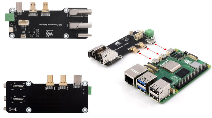
Celebrate the 4th Anniversary of Godeal24. Office 2021 Pro key is only $17.25/PC! (Sponsored)

Godeal24 has been selling Microsoft software license keys for over four years. Godeal24 is celebrating the milestone with a special sale, allowing you to buy Microsoft keys at discounted prices through the Godeal24 Fourth Anniversary Sale. Let’s take a look at the biggest offers on Microsoft keys. MS Office 2021 Pro key starts from $17.25 per PC! A historically low-priced software key that is available today! Microsoft Office 2021 Professional Plus is a lifetime license with instant delivery and download. It allows you to utilize Microsoft’s most popular apps, including Word, Excel, PowerPoint, Teams, and more. If you just want to buy one key for a single PC, then you only need to pay $27.25 to get a lifetime Office 2021 Pro key! Group purchases made together with family or friends unlock the most cost-effective offers! Godeal24 also sells Office 2019 Pro for $19.99 and Windows 11 Pro for $13.25. These deals tend to get snapped up quickly, so don’t hang about if interested.

Boost your productivity at a low cost! Limited-time offer!

Don’t settle for the ordinary – embrace the extraordinary with Windows 11 Pro!

Who is Godeal24?

Godeal24 is a global distributor of computer software with a very aggressive pricing policy. So, whether you are a freelance content creator, need video editing and image editing software, or want to strengthen the security of your computer with antivirus software, we invite you to look at all the offers from Godeal24: you will certainly find what you are looking for.

On Godeal24, the software is guaranteed to be 100% authentic. The site is 100% secure and the receipt of the key is done immediately by email after payment. Godeal24 promises that they offer 24/7 professional technical support and lifetime after-sales service and that you can use the product without problems! You can also contact Godeal24 by email ([email protected]) for support or inquiries.

The post Celebrate the 4th Anniversary of Godeal24. Office 2021 Pro key is only $17.25/PC! (Sponsored) appeared first on CNX Software - Embedded Systems News.
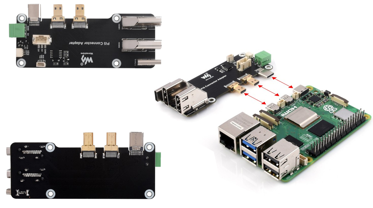
GEEKOM A8 Review – Part 2: An AMD Ryzen 9 8945HS mini PC tested with Windows 11 Pro

GEEKOM A8 mini PC Review Windows11 Pro

In the first part of the review, we’ve already gone through a teardown and an unboxing of the GEEKOM A8 AI mini PC powered by an AMD Ryzen 9 8945HS processor with AMD Radeon 780M Graphics, 32GB RAM (upgradeable up to 64GB) and a 2TB M.2 NVMe SSD.

We’ve now had more time to play with the GEEKOM A8, so we will report our experience with the Windows 11 Pro operating system in the second part of the review testing features, running benchmarks, evaluating networking and storage performance, testing the thermal design, and taking measurements for fan noise and power consumption.

GEEKOM A8 mini PC Review Windows11 Pro

Software overview and features testing

The System->About window in the Settings confirms we have an A8 Mini PC powered by a 4.0 GHz (base frequency) AMD Ryzen 9 8945HS processor with Radeon 780M Graphics and 32GB of RAM running Windows 11 Pro 23H2 build 22631.3593.

System About AMD Ryzen 9 8945HS

HWiNFO64 provides more details about the AMD Ryzen 9 8945HS octa-core/16-thread processor, motherboard, internal AMD Radeon 780M graphics, memory (2x 16GB DDR5-5600), and storage (Acer SSD N7000 2TB).

AMD Ryzen 9 8945HS HWiNFO

TechPowerUp GPU-Z gives us additional information about the AMD Radeon 780M Graphics.

GPU Z AMD Radeon 780M Graphics

The PL1 and PL2 power limits are set to 54W (PBP) and 65W (MTP) respectively, and the AMD processor is advertised as a 45W processor, so GEEKOM has not been as conservative with power limits as usual, maybe before the new “IceFlow 1.5” cooling system allows for better heat dissipation.

AMD Ryzen 9 8945HS power limits PL1 PL2

HWiNFO64 can also give us more information about memory. My GEEKOM A8 sample shipped with two Crucial Technology CT16G56C45SS DDR5 SO-DIMM modules with 16GB capacity each and based on Micron memory chips clocked at 2800 MHz (DDR5-5600) for a total capacity of 32 GB.

GEEKOM A8 DDR5 HWiNFO64

Windows Task Manager confirms we have 32GB RAM (or 31.3GB available to Windows) clocked at 5,600 MHz with two SODIMM modules. Note the NPU does not show here for some reasons… but it does in HWiNFO64.

GEEKOM A8 Memory Task Manager 5600MHz

Let’s now go to Device Manager->Network adapter to check 2.5Gbps Ethernet, WiFi 6E, and Bluetooth, all of which are shown.

GEEKOM A8 Device Manager Network Adapters

The GEEKOM A8 features a RealTek RTL8125 2.5GbE controller (Rev 05).

GEEKOM A8 2.5Gbps Ethernet

The MediaTek MT7922 WiFi 6E wireless card is shown to support up to 2,999 Mbps link speed, but we are connected at 206 Mbps albeit quite far from the router at the time of the screenshot. During the teardown, we saw the exact model number of the wireless module was “Azurewave AW-XB591NF”.

MediaTek MT7966 WiFi 6E Windows 11 Pro

We can check the Bluetooth version in Device Manager->MediaTek Bluetooth Adapter->Advanced.

GEEKOM A8 Bluetooth Version 5.3

LMP 12.xx looks up to Bluetooth 5.3. We’ve tested it successfully sending a file from the mini PC to an Android smartphone.

GEEKOM A8 Bluetooth File Transfer Test

All USB ports are properly marked, but let’s confirm the speed of the USB4, USB 3.2, and USB 2.0 ports on GEEKOM A8 using an ORICO M234C3-U4 M.2 NVMe SSD enclosure for USB 3.x/4 ports and a USB 3.0 hard drive for the USB 2.0 port, plus HWiNFO64 to verify the version and speed and CrystalDiskMark to confirm the transfer speed.

Here is an example with the left USB 3.2 Type-A port on the front panel.

GEEKOM A8 USB 3.2 port 1 speed

Same thing, but for the left USB4 port on the rear panel.

Geekom A8 USB4 speed

Finally, that’s the result for the USB 2.0 port.

GEEKOM A8 USB 2.0 Port Speed

Here’s a summary of the results of all six ports from left to right:

  • Front panel
    • USB-A #1 – USB 3.2 – USB 3.1 SuperSpeedPlus (10 Gbps) – Read speed: 895 MB/s; write speed: 932 MB/s
    • USB-A #2 – USB 3.2 – USB 3.1 SuperSpeedPlus (10 Gbps) – Read speed: 895 MB/s; write speed: 930 MB/s
  • Rear panel
    • USB-C #1 – USB4 (40 Gbps) – Thunderbolt/NVMe 8GT/s – Read speed: 2,205 MB/s; write speed: 813 MB/s
    • USB-A #1 (top) – USB 3.2 – USB 3.1 SuperSpeedPlus (10 Gbps) – Read speed: 965 MB/s; write speed: 954 MB/s
    • USB-A #2 (bottom) – USB 2.0 – USB 2.0 Hight-Speed (480 Mbps) – Read speed: 43 MB/s; write speed: 35 MB/s
    • USB-C #2 – USB 3.2 – USB 3.1 SuperSpeedPlus (10 Gbps) – Read speed: 965 MB/s; write speed: 952 MB/s

All ports work as expected considering the bottleneck for the USB4 is the read speed (2,200 MB/s) of the Apacer SSD used for testing.

The GEEKOM A8 is equipped with two HDMI 2.0 ports and two USB 4 ports with DisplayPort Alt mode and supports up to four independent 4K displays. We don’t have 4K monitors, but we still tested the four video outputs.

Mini PC dual HDMI 2.0 dual USB4 Type C display ports

We could use four monitors in extended desktop mode namely the 14-inch CrowView laptop monitor (USB-C), two 15.6-inch CrowVi portable monitors (USB-C and HDMI), and a Kamvas Pro 16 (2.5K) “drawing tablet” connected over HDMI.

GEEKOM A8 Four independent displays

GEEKOM A8 benchmarks on Windows 11 Pro

We set the Power mode to “Best performance” in the settings before running Windows 11 benchmarks on the GEEKOM A8 Pro mini PC.

Windows 11 Ryzen 9 Power mode Best performance

Let’s start with PCMark 10 for testing the overall system performance.

PCmark 10 GEEKOM A8

That would be 7,693 points in PCMark 10.

GEEKOM A8 3DMARK

Next up to 3DMark, where the system achieved 7,736 points.

PassMark PerformanceTest 11 Geekom A8

GEEKOM A8 got 8,543.4 points in PassMark PerformanceTest 11 with an impressive Disk Mark result in the 97th percentile which may impact the overall PassMark rating quite a lot.

CrystalDiskMark GEEKOM A8 NVMe SSD

So we also run CrystalDiskMark to evaluate the 2TB NVMe SSD performance and the results are impressive with 7,000 MB/s sequential read speed and 6,262 MB/s sequential write speed. It’s the highest performance of all mini PCs we’ve reviewed so far. The random I/Os look good too, although the WD PC SN740 NVMe SSD in the Khadas Mind Premium is better in RND4K tests.

Cinebench R23 was used to test single-core and multi-core performance.

AMD Ryzen 9 8945HS Cinebench R23

The single-core score was 1,768 points, while the multi-core score was 15,088 points or an MP ratio of 8.54x for an octa-core/16-thread processor.

We’ll start GPU testing with Unigine Heaven Benchmark 4.0 where the system averaged 68.0 fps and achieved a 1,712 points score at 1920×1080 resolution.

AMD Ryzen 9 8945HS Unigine Heaven Benchmark 4.0 Windows 11

Let’s test YouTube 4K and 8K in Google Chrome.

GEEKOM A8 Windows 11 YouTube 4K 30 FPS

Our YouTube 4K 30 FPS video sample played perfectly with no frames dropped at all after a 7-minute test.

GEEKOM A8 Windows 11 YouTube 8K 30 FPS

Same thing for 8K at 30 FPS.

GEEKOM A8 Windows 11 YouTube 4K 60 FPS

Switching to 4K 60 FPS (2160p60) was fine too, but there were a few dropped frames (24) out of 24,212.

GEEKOM A8 Windows 11 YouTube 8K 60 FPS

The GEEKOM A8 can also handle 8K 60 FPS video just fine with the video playing smoothly, and only 65 frames dropped out of 26,450. We also tested audio through HDMI and the 3.5mm audio jack while watching the YouTube videos, and there were no issues.

Since the AMD Ryzen 9 8945HS processor comes with a 16 TOPS NPU and can deliver up to 39 TOPS we also tried to test AI workloads. We started running Geekbench ML 0.6.0 on the CPU where the system got 3,859 points.

GEEKOM A8 Geekbench ML CPU score

Then Geekbench ML 0.6.0 was run with ONNX DirectML which should have used the GPU and AI accelerator.

Geekbench ML 0.6.0 score with DirectML

The score is indeed higher with DirectML, but as you’ll see in the comparison between the two runs sometimes the CPU is faster… We did try AI samples on Ryzen 9 7840HS (GEEKOM A7) last February, but it was a giant mess with many of the samples not compiling or running properly. PerfML is supposed to be the reference benchmark for AI/ML workloads, but the documentation is a mess and it looks like each (micro) benchmark needs to be run individually…

Comparison of GEEKOM A8 Windows 11 benchmarks against other mini PCs

Let’s now compare the Windows 11 benchmark results of the GEEKOM A8 against other high-end mini PC include the GEEKOM A7 (AMD Ryzen 9 7840HS), GEEKOM XT12 Pro (Intel Core i9-12900H), GEEKOM Mini IT13 (Intel Core i9-13900H), and Khadas Mind Premium (Intel Core i7-1360P).

Here’s a summary of the key features of the five mini PCs.

GEEKOM A8GEEKOM A7GEEKOM XT12 ProGEEKOM IT13Khadas Mind Premium
SoCAMD Ryzen 9 8945HSAMD Ryzen 9 7840HSIntel Core i9-12900HIntel Core i9-13900HIntel Core i7-1360P
CPU8-core/16-thread processor up to 5.2 GHz 8-core/16-thread processor up to 5.1GHz14-core/20-thread (6P+8E) Alder Lake processor up to 5.00 GHz (P-cores), up to 3.80 GHz (E-Cores)14-core/20-thread (6P+8E) Raptor Lake processor up to 5.40 GHz (P-cores), up to 4.10 GHz (E-Cores)12-core/16-core (4P+8E) Raptor Lake processor up to 5.00 GHz (P-cores), up to 3.70 GHz (E-Cores)
GPUAMD Radeon 780M GraphicsAMD Radeon 780M Graphics96EU Intel Iris Xe Graphics96 EU Intel Iris Xe Graphics96 EU Intel Iris Xe Graphics
Memory32GB DDR5-560032GB DDR5-560032GB DDR4-320032GB DDR4-320032GB LPDDR5-5200
Storage2TB NVMe SSD2TB NVMe SSD1TB NVMe SSD2TB NVMe SSD1TB NVMe SSD
Default OSWindows 11 ProWindows 11 ProWindows 11 ProWindows 11 ProWindows 11 Home

And now the benchmark results on Windows 11.

GEEKOM A8GEEKOM A7GEEKOM XT12 ProGEEKOM Mini IT13Khadas Mind Premium
PCMark 107576
7516
60636681
5904
- Essentials1165011528111601193811038
- Productivity1051010370737683417589
- Digital content creation96399639734481266667
3DMark (Fire Strike)77368534498253875427
PerformanceTest 11.08543.48058.250855580.45378
- CPU Mark30090.430719.82333825363.121786
- 2D Graphics Mark903.9931.9777547.6631
- 3D Graphics Mark7984.97226.134443728.2
3622
- Memory Mark3308.83391.432593925.93642
- Disk Mark49560.4385903100338135.542395
Cinebench R23
- Single Core1768183117691943
1878
- Multi Core1508815231746611855
9384

The results are not that different between the GEEKOM A7 and A8, and the main highlight is the faster NVMe SSD in the A8… Both AMD systems perform quite better than the Intel mini PCs.

Network performance testing  (2.5GbE and WiFi 6)

We’ll use the iperf3 utility to test both Ethernet and WiFi using the UP Xtreme i11 Edge mini PC on the other side.

Let’s start with 2.5Gbps Ethernet:

  • Download

PS C:\Users\aey\Downloads\iperf3.17.1_64\iperf3.17.1_64> .\iperf3.exe -t 60 -c 192.168.31.12 -i 10 -R
Connecting to host 192.168.31.12, port 5201
Reverse mode, remote host 192.168.31.12 is sending
[  5] local 192.168.31.69 port 59883 connected to 192.168.31.12 port 5201
[ ID] Interval           Transfer     Bitrate
[  5]   0.00-10.00  sec  2.76 GBytes  2.37 Gbits/sec
[  5]  10.00-20.01  sec  2.76 GBytes  2.37 Gbits/sec
[  5]  20.01-30.01  sec  2.76 GBytes  2.37 Gbits/sec
[  5]  30.01-40.01  sec  2.76 GBytes  2.37 Gbits/sec
[  5]  40.01-50.01  sec  2.76 GBytes  2.37 Gbits/sec
[  5]  50.01-60.01  sec  2.76 GBytes  2.37 Gbits/sec
- - - - - - - - - - - - - - - - - - - - - - - - -
[ ID] Interval           Transfer     Bitrate         Retr
[  5]   0.00-60.06  sec  16.6 GBytes  2.37 Gbits/sec    0             sender
[  5]   0.00-60.01  sec  16.6 GBytes  2.37 Gbits/sec                  receiver

iperf Done.

  • Upload

PS C:\Users\aey\Downloads\iperf3.17.1_64\iperf3.17.1_64> .\iperf3.exe -t 60 -c 192.168.31.12 -i 10
Connecting to host 192.168.31.12, port 5201
[  5] local 192.168.31.69 port 59873 connected to 192.168.31.12 port 5201
[ ID] Interval           Transfer     Bitrate
[  5]   0.00-10.01  sec  2.77 GBytes  2.37 Gbits/sec
[  5]  10.01-20.01  sec  2.76 GBytes  2.37 Gbits/sec
[  5]  20.01-30.01  sec  2.76 GBytes  2.37 Gbits/sec
[  5]  30.01-40.01  sec  2.76 GBytes  2.37 Gbits/sec
[  5]  40.01-50.01  sec  2.76 GBytes  2.37 Gbits/sec
[  5]  50.01-60.01  sec  2.76 GBytes  2.37 Gbits/sec
- - - - - - - - - - - - - - - - - - - - - - - - -
[ ID] Interval           Transfer     Bitrate
[  5]   0.00-60.01  sec  16.6 GBytes  2.37 Gbits/sec                  sender
[  5]   0.00-60.08  sec  16.6 GBytes  2.37 Gbits/sec                  receiver

iperf Done.

Perfect no issue whatsoever. Let’s do the same with WiFi 6 adding Xiaomi Mi AX6000 router to the testbed since we don’t own a WiFi 6E capable router. But remember that we broke one of the WiFi antennas while opening the device in the first part of the review. So we’ll test with one antenna only first.

  • Download

PS C:\Users\aey\Downloads\iperf3.17.1_64\iperf3.17.1_64> .\iperf3.exe -t 60 -c 192.168.31.12 -i 10 -R
Connecting to host 192.168.31.12, port 5201
Reverse mode, remote host 192.168.31.12 is sending
[  5] local 192.168.31.59 port 59770 connected to 192.168.31.12 port 5201
[ ID] Interval           Transfer     Bitrate
[  5]   0.00-10.01  sec   998 MBytes   836 Mbits/sec
[  5]  10.01-20.01  sec  1.17 GBytes  1.00 Gbits/sec
[  5]  20.01-30.01  sec  1.11 GBytes   953 Mbits/sec
[  5]  30.01-40.01  sec  1.11 GBytes   950 Mbits/sec
[  5]  40.01-50.01  sec  1.15 GBytes   992 Mbits/sec
[  5]  50.01-60.01  sec  1.14 GBytes   977 Mbits/sec
- - - - - - - - - - - - - - - - - - - - - - - - -
[ ID] Interval           Transfer     Bitrate         Retr
[  5]   0.00-60.05  sec  6.65 GBytes   952 Mbits/sec  2002             sender
[  5]   0.00-60.01  sec  6.65 GBytes   952 Mbits/sec                  receiver

iperf Done.

  • Upload

PS C:\Users\aey\Downloads\iperf3.17.1_64\iperf3.17.1_64> .\iperf3.exe -t 60 -c 192.168.31.12 -i 10
Connecting to host 192.168.31.12, port 5201
[  5] local 192.168.31.59 port 59761 connected to 192.168.31.12 port 5201
[ ID] Interval           Transfer     Bitrate
[  5]   0.00-10.01  sec   889 MBytes   745 Mbits/sec
[  5]  10.01-20.00  sec  1.10 GBytes   946 Mbits/sec
[  5]  20.00-30.00  sec  1.10 GBytes   945 Mbits/sec
[  5]  30.00-40.01  sec  1.11 GBytes   951 Mbits/sec
[  5]  40.01-50.01  sec  1.11 GBytes   956 Mbits/sec
[  5]  50.01-60.00  sec  1.10 GBytes   946 Mbits/sec
- - - - - - - - - - - - - - - - - - - - - - - - -
[ ID] Interval           Transfer     Bitrate
[  5]   0.00-60.00  sec  6.39 GBytes   915 Mbits/sec                  sender
[  5]   0.00-60.06  sec  6.39 GBytes   914 Mbits/sec                  receiver

iperf Done.

Note we are using iperf 3.17.1 as earlier versions like iperf 3.1.3 are slower. 952 Mbps download and 914 Mbps are not bad results, even with only one antenna. But what happens with an extra IPEX4 antenna?

Repair WiFi Antenna IPEX4 in mini PC

This time we stuck the antenna on the side since it was initially placed on the bottom cover and was prone to be broken when the user opened the device to change the RAM or install another SSD. We wrote a short tutorial showing how to change the WiFi antenna for those who may experience the same issue.

  • Download

PS C:\Users\aey\Downloads\iperf3.17.1_64\iperf3.17.1_64> .\iperf3.exe -t 60 -c 192.168.31.12 -i 10 -R
Connecting to host 192.168.31.12, port 5201
Reverse mode, remote host 192.168.31.12 is sending
[  5] local 192.168.31.59 port 57808 connected to 192.168.31.12 port 5201
[ ID] Interval           Transfer     Bitrate
[  5]   0.00-10.01  sec   844 MBytes   708 Mbits/sec
[  5]  10.01-20.01  sec  1.42 GBytes  1.22 Gbits/sec
[  5]  20.01-30.01  sec  1.35 GBytes  1.16 Gbits/sec
[  5]  30.01-40.01  sec  1.58 GBytes  1.36 Gbits/sec
[  5]  40.01-50.01  sec  1.60 GBytes  1.37 Gbits/sec
[  5]  50.01-60.01  sec  1.58 GBytes  1.36 Gbits/sec
- - - - - - - - - - - - - - - - - - - - - - - - -
[ ID] Interval           Transfer     Bitrate         Retr
[  5]   0.00-60.06  sec  8.35 GBytes  1.19 Gbits/sec  1129             sender
[  5]   0.00-60.01  sec  8.35 GBytes  1.20 Gbits/sec                  receiver

iperf Done.

  • Upload

PS C:\Users\aey\Downloads\iperf3.17.1_64\iperf3.17.1_64> .\iperf3.exe -t 60 -c 192.168.31.12 -i 10
Connecting to host 192.168.31.12, port 5201
[  5] local 192.168.31.59 port 57820 connected to 192.168.31.12 port 5201
[ ID] Interval           Transfer     Bitrate
[  5]   0.00-10.01  sec  1.83 GBytes  1.57 Gbits/sec
[  5]  10.01-20.00  sec  1.85 GBytes  1.59 Gbits/sec
[  5]  20.00-30.00  sec  1.87 GBytes  1.60 Gbits/sec
[  5]  30.00-40.01  sec  1.86 GBytes  1.60 Gbits/sec
[  5]  40.01-50.01  sec  1.90 GBytes  1.63 Gbits/sec
[  5]  50.01-60.01  sec  1.71 GBytes  1.47 Gbits/sec
- - - - - - - - - - - - - - - - - - - - - - - - -
[ ID] Interval           Transfer     Bitrate
[  5]   0.00-60.01  sec  11.0 GBytes  1.58 Gbits/sec                  sender
[  5]   0.00-60.07  sec  11.0 GBytes  1.57 Gbits/sec                  receiver

iperf Done.

1.20 Gbps downloads and 1.57 Gbps uploads are even more impressive, and that’s the fastest WiFi 6 speeds we ever got in our testbed.

Thermal performance

To test the cooling efficiency of the mini PC, we ran the 3Dmark Fire Strike benchmark while monitoring the system with HWiNFO64 to check the maximum CPU temperature under CPU+GPU load, with a maximum temperature of 93.1°C and no thermal CPU throttling detected by the utility.

AMD Ryzen 9 8945HS Thermal Test 3DMark Fire Strike

That’s the same results as in GEEKOM A7, except the maximum temperature was a bit higher at 95.6°C.

Fan noise

The mini PC’s fan is barely audible most of the time but becomes somewhat noisy under heavy loads.  We used a sound level meter 5 cm from the top of the device to measure the fan noise:

  • Idle – 37.8 to 41.3 dBA
  • 3Dmark’s Fire Strike – 40.8 – 58.6 dBA

The room’s background noise is 37 to 38 dBa. The results are again very similar to the ones for the GEEKOM A7.

GEEKOM A8 power consumption

GEEKOM A8’s power consumption was measured while running Windows 11 Pro using a wall power meter as follows:

  • Power off – 1.5 Watts
  • Idle – 6.5 to 7.0 Watts
  • Video playback – 20.72 – 43.0 Watts (YouTube 8K 60fps in Chrome)
  • 3DMark’s Fire Strike – 47.2 – 52.2 Watts
  • Cinebench R23 Multi-core
    • First few seconds – 64.6 – 70.9 Watts
    • Long run – 61.3 – 64.5 Watts

The mini PC was connected to WiFi 6, an RF dongle for a keyboard, a USB mouse, and the CrowVi display through an HDMI cable and a separate USB-C power adapter.

Conclusion

The GEEKOM A8 offers performance similar to the GEEKOM A7 we reviewed a few months ago, meaning the AMD Ryzen 9 8945HS system is one of the fastest mini PCs we’ve ever reviewed.  You should be able to run pretty much anything that you’d normally do on a larger PC, even play some AAA games, although the iGPU won’t quite match the performance of discrete graphics cards from NVIDIA or AMD.

The GEEKOM A8 does offer some improvements over the A7 in Windows 11 Pro with 8K 60 FPS video streaming working perfectly and a faster NVMe SSD (the fastest we ever tested based on sequential read/write speeds). All features we tested worked fine including driving four independent displays through HDMI and USB ports, USB4/Thunderbolt support, and audio output from HDMI and the headphone jack. Both 2.5GbE and WiFi 6 also work great. We did not experience CPU throttling, and the mini PC’s fan is quiet most of the time. It only really kicks up under heavier loads, but even then the noise is not too annoying.

What I don’t know what to do with right now is the AI Engine, since there don’t seem to be any (killer) applications that make use of it. I can see some work-on-progress support on software such as Hugging Faces, but I assume it will take a bit more time before it becomes useful to end users.

We’d like to thank GEEKOM for sending us the A8 mini PC for review with an AMD Ryzen 9 8945HS, 32GB DDR5, and a 2 TB SSD. The model reviewed here can be purchased on Amazon for $806.55 with coupon code CNXSWGA8, and you’ll also find it on the GEEKOM US and GEEKOM UK stores with similar pricing when using the discount coupon CNXA8 for a 5% discount. The coupon codes are valid until July 10, 2024. There’s also a cheaper GEEKOM A8 model based on the Ryzen 7 8845HS CPU.

CNXSoft: This article is a translation – with some additional insights – of the original review on CNX Software Thailand by Suthinee Kerdkaew.

The post GEEKOM A8 Review – Part 2: An AMD Ryzen 9 8945HS mini PC tested with Windows 11 Pro appeared first on CNX Software - Embedded Systems News.
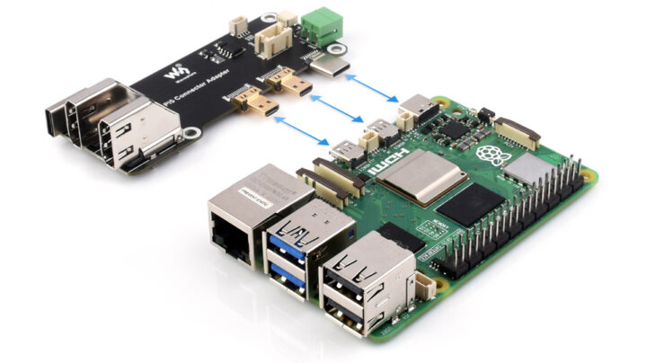
MYiR Tech launches AMD XC7A100T Artix-7 FPGA system-on-module and development board with PCIe, SFP+ cages, dual GbE

AMD XC7A100T FPGA development board

MYIR MYC-J7A100T is a System-On-Module (SoM) powered by an AMD/Xilinx Artix-7 XC7A100T FPGA with up to 101,440 logic cells, 512MB DDR3 memory, 32MB QSPI FLASH, 32KB EEPROM, DC-DC power management, and other integral circuits in a compact 69.6 x 40mm form factor.

The module exposes up to 178 FPGA I/Os, four pairs of GTP high-speed transceiver interfaces, and a JTAG interface through its 260-pin edge connector. MYiR also provides a development board for the MYC-J7A100T module which looks like a PCIe 2.0 card and comes with SFP+ cages, HDMI input and output ports, dual GbE, and a GPIO expansion header.

MYIR MYC-J7A100T system-on-module

AMD XC7A100T Artix 7 FPGA system-on-module

Specifications:

  • FPGA – AMD/Xilinx XC7A100T Artix-7 FPGA (XC7A100T-2FGG484I) with
    • 101,440 logic cells
    • 4,860 Kb of Block RAM
    • 240 DSP slices
    • 8 GTP transceivers capable of reaching speeds up to 6.6Gb/s
    • PCIe Gen2 x4  interface
    • Up to 300x single-ended I/Os
  • System Memory – 512MB DDR3
  • Storage – 32MB QSPI Flash, 32KB EEPROM
  • Carrier board interface – 260-pin edge connector
    • 178x programmable I/Os
      • Bank 13 – 35 I/Os
      • Bank 14 – 45 I/Os
      • Bank 15 – 48 I/Os
      • Bank 16 – 50 I/Os
    • MGTP – 20-pin for high-speed serial interfaces
    • JTAG Debug
  • Supply Voltage – 5V, 3A recommended
  • Dimensions – 69.6 x 40mm (12-layer PCB design)
  • Temperature Range – 40 to 85 Celsius (industrial grade)

SoM with 260-pin MXM connector

MYIR MYD-J7A100T AMD XC7A100T FPGA development board

AMD XC7A100T FPGA development board

The company also provides the MYD-J7A100T development board fitted with the MYC-J7A100T SoM and offering the following interfaces:

  • 260-pin socket for MYIR MYC-J7A100T system-on-module described above
  • Storage – MicroSD card slot
  • Video Interfaces
    • HDMI input and output
    • DVP digital camera interface with support for MYIR’s MY-CAM011B 2MP camera module
  • Networking
    • 2x SFP+ cages
    • 2x Gigabit Ethernet RJ45 interfaces
  • Expansion
    • PCIe 2.0 interface
    • 40-pin male expansion header for MY-WIREDCOM RPI module adding RS232/RS485 interfaces
  • Debugging – JTAG; USB-to-UART interface via USB Type-C port
  • Misc
    • 3x buttons
    • 3x LEDs
    • 1x DIP switch for Boot selection and Power On/OFF
  • Power Supply – 12V/2A via DC power jack
  • Dimensions – 167.64 x 130.65mm (6-layer PCB design)
  • Temperature Range – -40 to +85 Celsius
MYC-J7A100T development board block diagram

Software, price, and availability

MYiR Tech provides a range of Vivado sample codes for testing purposes from a basic LED blinky to more complex HDMI input/output, PCIe, and SFP+ test programs. The company will not typically make those public and only provides software resources to paying customers.

It’s unclear why MYiR decided to launch Artix-7 FPGA at this time as the Xilinx (now AMD) XC7A100T FPGA has been around for many years, and we previously covered Trenz Electronic TE0725LP board in 2019 and the MicroNova Mercury 2 in 2020. We also wrote about a 3D game engine C to FPGA implementation running on Digilent Arty A7-100T board with the same XC7A100T FPGA.

The solution is said to be suitable for industrial control, automation, communication, computing, and other highly customized applications. MYIR MYC-J7A100T system-on-module and  MYD-J7A100T AMD XC7A100T FPGA development board are available now for $125 and $169 respectively. More details, including hardware documentation and purchase links, can be found on the product page.

The post MYiR Tech launches AMD XC7A100T Artix-7 FPGA system-on-module and development board with PCIe, SFP+ cages, dual GbE appeared first on CNX Software - Embedded Systems News.
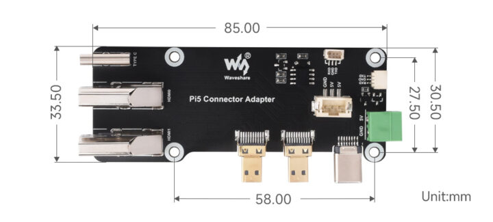
PCIe to 5G HAT+ for Raspberry Pi 5 takes SIMCom and Quectel 5G modules

Raspberry Pi 5 5G PCIe HAT+

Waveshare PCIe to 5G/4G/3G HAT+ for Raspberry Pi 5 is a PCIe Gen 2 x1 to M.2 HAT+ designed to take 5G modules from SIMCom and Quectel and a Nano SIM card. The kit ships with a 4-in-1 PCB antenna, associated cables, a heatsink, a 4cm 16-pin PCIe FPC cable, a 40-pin female header, and a fixture set for mounting.

We had previously written about the SixFab 5G HAT for the Raspberry Pi 5 with a Quectel RM502Q-AE M.2 module, but this specific kit still relies on the USB 3.0 interface. The Waveshare kit is the first 5G kit using the PCIe interface from the Raspberry Pi 5 interface and it is offered with Quectel RM502Q-AE, RM530N-GL, RM520N-GL, or SIMCom SIM8262E-M2, SIM8262A-M2 M.2 3042/3052 modules.

Raspberry Pi 5 5G PCIe HAT+

Waveshare PCIe to 5G HAT+ specifications:

  • M.2 Key B socket for 3042/3052 5G modules with PCIe interface
  • 16-pin PCIe FPC connector directly connected to the Raspberry Pi 5 PCIe interface
  • 40-pin GPIO header
  • Nano SIM card slot
  • Antenna – 4-in-1 PCB antenna board with four IPEX antennas
  • USB – USB Type-C port for 5G networking of Raspberry Pi or PC via USB cable, firmware updating, or external power supply input
  • Storage – I2C EEPROM for configuration
  • Misc – Reset button, Power and Network LEDs
  • Power Management – Onboard power monitoring chip for real-time measurement of voltage, current, and power
  • Dimensions – HAT+ form factor

Waveshare PCIe to 5G 4G 3G HAT Raspberry Pi 5Waveshare provides support for five different 5G modules suitable for various regions across the globe:

  • Quectel Modules
    • RM502Q-AE (Global except China) – 3GPP R15, Sub-6 GHz
    • RM520N-GL (Global) – 3GPP R16, Sub-6 GHz 
    • RM530N-GL (Global) – 3GPP R16, Sub-6 GHz, mmWave
    • Bands
      • 5G NR (RM530N-GL only) – n257, n258, n260, n261
      • 5G NR NSA/SA – n1, n2, n3, n5, n7, n8, n12, n20, n25, n28, n38, n40, n41, n48, n66, n71, n77, n78, n79; RM520N/RM530N add: n13, n14, n18, n29, n30, n70, n71, n76
      • 4G LTE-FDD – B1, B2, B3, B4, B5, B7, B8, B12, B13, B14, B17, B18, B19, B20, B25, B26, B28, B29, B30, B32, B66, B71
      • 4G LTE-TDD – B34, B38, B39, B40, B41, B42, B43, B48
      • LAA – B46
      • WCDMA – B1, B2, B4, B5, B8, B19; RM502Q-AE adds: B3 and B6
    • GNSS – GPS / GLONASS / BeiDou (Compass) / Galileo / QZSS (QZSS is not supported on RM502Q-AE)
    • Data rates
      • 5G mmWave – Downlink 4 Gbps; uplink 1.4 Gbps
      • 5G SA Sub-6
        • RM502Q-AE – downlink 4.2 Gbps; uplink 450 Mbps
        • RM520N-GL/RM530N-GL – downlink 2.4 Gbps; uplink 900 Mbps
      • 5G NSA Sub-6
        • RM502Q-AE – downlink 5 Gbps; uplink 650 Mbps
        • RM520N-GL/RM530N-GL – downlink 3.4 Gbps; uplink 550 Mbps
      • 4G LTE
        • RM502Q-AE – downlink 2 Gbps; uplink 200 Mbps
        • RM520N-GL – downlink 1.6 Gbps; uplink 200 Mbps
        • RM530N-GL – downlink 1.0 Gbps; uplink 200 Mbps
      • 3G UMTS – downlink 42 Mbps; uplink 5.76 Mbps
  • SIMCom modules
    • SIM8262E-M2 (except Americas) – Sub-6 GHz
    • SIM8262A-M2 (Americas) – Sub-6 GHz
    • Bands
      • 5G NR NSA/SA
        • SIM8262E-M2 – n1, n3, n5, n7, n8, n20, n28, n38, n40, n41, n77, n78, n79
        • SIM8262A-M2 – n2, n5, n7, n12, n13, n14, n25, n30, n41, n48, n66, n71, n77, n78, n79
      • 4G LTE
        • LTE-FDD
          • SIM8262E-M2 – B1, B3, B5, B7, B8, B18, B19, B20, B26, B28, B32
          • SIM8262A-M2 – B2, B4, B5, B7, B12, B13, B14, B25, B26, B29, B30, B66, B71
        • LTD-TDD
          • SIM8262E-M2 – B38, B39, B40, B41, B42, B43
          • SIM8262A-M2 – B2, B41, B46, B48
      • UMTS
        • SIM8262E-M2 – B1, B5, B8
        • SIM8262A-M2 – B2, B4, B5
    • GNSS – GPS / GLONASS / BeiDou / Galileo / QZSS
    • Data rates
      • 5G – downlink 2.4 Gbps; uplink 500 Mbps
      • 4G LTE –  downlink 1.0 Gbps; uplink 200 Mbps
      • UMTS – downlink 42 Mbps; uplink 5.76 Mbps
Waveshare PCIe 5G HAT assembly instructions
Assembly instructions

Waveshare provides documentation for each module and how to use them with the PCIe to 5G HAT+, for example for the Quectel RM530N-GL, but each Wiki page is very similar, includes AT commands for both Quectel and SIMCom modules, and configuration steps with Raspberry Pi OS and OpenWrt.

All five Waveshare PCIe to 5G HAT kits can be purchased on Aliexpress for $259.43 to $338.55 depending on the selected model, and you’ll also find those on Amazon or directly on the Waveshare online store.

The post PCIe to 5G HAT+ for Raspberry Pi 5 takes SIMCom and Quectel 5G modules appeared first on CNX Software - Embedded Systems News.
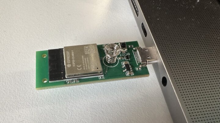
DFM8001 indoor energy harvesting kit harnesses solar energy (and mechanical, thermal, RF energy with extra hardware)

DFM8001 Indoor Ambient Energy Harvesting Kit

DFRobot DFM8001 indoor ambient energy harvesting kit can power IoT devices by harnessing solar energy, and the company claims it can also capture mechanical, thermal, and RF energy from the local environment but there’s no way to do that with that kit without additional hardware.

The DFRobot kit is comprised of an evaluation board with the company DFM8001 energy harvesting module, two pluggable supercapacitors, and a solar panel used as power input. You could also use other sources emitting at least 150 mV gathering energy from RF, thermal, or mechanical sources. The board features two outputs one low-voltage (1.2-1.8V) terminal up to 20mA, and a high-voltage (1.8V-4.1V) terminal up to 80mA, and two battery connectors plus a few jumpers for configuration.

DFM8001 Indoor Ambient Energy Harvesting Kit

DFM8001 energy harvesting kit specifications:

  • Operating voltage – 3.3V to 5.5V DC
  • Cold start condition – Input > 400mV 15uW
  • Sustaining voltage after cold start – 150mV.
  • Input voltage range – 150mV – 5V through 2-pin SRC IN terminal block
  • MPPT ratio – 70%, 75%, 85%, 90% (adjustable)
  • MPPT automatic detection frequency – 5 times per second
  • Dual LDO voltage regulation output
    • 2-pin Low voltage terminal – 1.2 to 1.8V up to 20mA (enabled/disabled with jumper), e.g. for low-power MCU board
    • 2-pin High voltage terminal – 1.8 to 4.1V up to 80mA (enabled/disabled with jumper), e.g. for low-power RF receiver
  • Energy storage management
    • 1.5F and 0.22F supercapacitor energy storage modules (connected through 4-pin + 3-pin headers)
    • 2-pin PRIM terminal block for primary battery
    • 3-pin BAT terminal block for external energy storage device with +, -, and DCSC.
    • Adjustable overcharge protection – 2.7V – 4.5V
    • Adjustable over-discharge protection – 2.2V – 3.6V
    • Low battery warning
    • LDO output available indication
    • Switch to backup battery after 600ms
  • Supports disposable backup battery
  • Solar panel
    • Maximum power point – 70%
    • Maximum power – 90uW @ 200Lux
  • Dimensions
    • Module – 15 x 15 x 3.5 mm
    • Evaluation board – 57 x 42 mm
    • Amorphous silicon solar panel –  45 x 45 mm
  • Temperature Range (for DFM8001 module only) – Operating: -40°C to +125°C; storage: -40°C to +150°C

DFM8001 indoor ambient energy harvesting kit description

DFRobot DFM8001 connection diagram
Connection diagram
energy harvesting module pinout diagram
DFM8001 module block diagram

The documentation for the evaluation kit could be better, but I suppose that’s enough to get started. You’ll also find another wiki for the DFM8001 module specifically. The company says that besides the basic amorphous silicon solar panel provided in the kit, users can use higher-efficiency photovoltaic panels such as organic or dye-sensitized solar panels.

Typically applications include indoor light energy harvesting, self-powered Internet of Things (IoT) nodes, Smart Home systems, industrial monitoring, asset management, and Ambient IoT. DFRobot sells the DFM8001 indoor ambient energy harvesting kit for $16.90.  You can also buy the DFM8001 module by itself for $4.90.

The post DFM8001 indoor energy harvesting kit harnesses solar energy (and mechanical, thermal, RF energy with extra hardware) appeared first on CNX Software - Embedded Systems News.
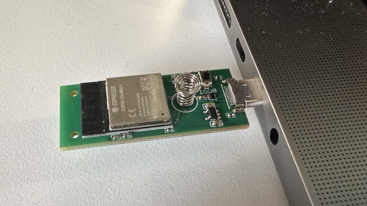
$70 Raspberry Pi AI Kit combines official M.2 HAT+ with Hailo-8L AI accelerator

Raspberry Pi AI Kit Raspberry Pi 5

Raspberry Pi Limited has just launched the “Raspberry Pi AI Kit”  comprised of the official M.2 Key M HAT+ and a 13 TOPS Hailo-8L M.2 AI accelerator module and selling for $70 through distributors.

We had seen Raspberry Pi showcase an AI camera at Embedded World 2024, so when I received an email from a representative about a “Raspberry Pi AI Kit” I thought it would be the announcement about the camera. Instead, it’s a kit comprised of existing parts with the most interesting aspects being the price and availability (hopefully) since Hailo-8/8L accelerators are mostly found in more expensive embedded/industrial solutions, and easier documentation to get started.

Raspberry Pi AI Kit Raspberry Pi 5

Raspberry Pi AI Kit highlights:

  • Support SBC – Raspberry Pi 5
  • M.2 HAT+ with PCIe Gen2 x1 interfaces, M.2 Key M support,
  • Hailo-8L AI accelerator with
    • Up to 13 TOPS of performance
    • M.2 2242 form factor
    • Typical power consumption – 1.5W
  • Thermal pad pre-fitted between the module and the M.2 HAT+
  • Mounting hardware kit
  • 16mm stacking GPIO header
  • PCIe FPC cable

Raspberry Pi AI Kit object detection

There’s nothing really special about the hardware, but Raspberry Pi and Hailo collaborated on the software and you’ll find a range of AI-accelerated computer vision samples for the Raspberry Pi 5, including object detection, pose estimation, and instance segmentation on GitHub, along with documentation on the Raspberry Pi website.

The main advantage of using an AI accelerator such as the Hailo-8L over the CPU or GPU on a Raspberry Pi 5 is the lower power consumption and much faster AI processing as can be seen on the pose estimation demo shown in the video embedded below.

More sample programs leveraging the new Raspberry Pi AI kit are coming soon notably a CLIP (Contrastive Language-Image Pretraining) program that predicts the most relevant text prompt on real-time video frames using the Hailo-8L AI processor. Raspberry Pi also worked on Raspberry Pi rpicam-apps making use of the Pi cameras, and work is being done on picamera2 to support Hailo-8L through a Python API.

The post $70 Raspberry Pi AI Kit combines official M.2 HAT+ with Hailo-8L AI accelerator appeared first on CNX Software - Embedded Systems News.
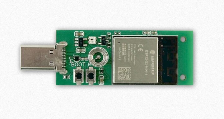
GCT GDM7243SL is a dual-core RISC-V 5G/4G LTE modem with support for NTN, NB-IoT, LTE Cat M, Cat1bis, Cat1 and/or Cat4

GDM7243SL2 block diagram

CT Semiconductor Holding GDM7243SL is a multi-mode 5G/4G LTE IoT modem with two 400 MHz RISC-V cores capable of operating in Cat 4, Cat 1bis, Cat M1, Cat NB1/NB2 (NB-IoT) and non-terrestrial networks (NTN) in order to work anywhere on earth.

If I remember correctly, one of the first commercial RISC-V SoCs I saw was a storage controller from Western Digital introduced in 2019. But since then, we’ve seen more and more RISC-V chips come to market from entry-level microcontrollers up to Linux-capable application processors, and even chips for datacenters that are out of the scope of topics covered on CNX Software. But with GDM7243SL, I think it’s the first time I’ve encountered a RISC-V modem, so let’s have a closer look.

GDM7243SL2 block diagram

There are two models, the GDM7243SL1 and GDM7243SL2, with different memory and storage options, and the L1 lacks support for LTE Cat 4.

GDM7243SL key features:

  • CPU
    • 400 MHz RISC-V application core running Linux, OpenWRT, PRPL, or Zephyr
    • 400 MHz RISC-V modem firmware/RTOS core
  • Storage and Memory
    • GDM7243SL1 – 16MB p-SRAM, 16MB s-Flash
    • GDM7243SL2 – 128MB LPDDR2, NAND flash interface
  • 5G/4G LTE Modem
    • FDD-LTE/TDD-LTE (3GPP E-UTRA) PHY and MAC
      • 2×2/4×2 MIMO
      • LTE Cat 1, Cat 1 bisGDM7243SL2 also adds Cat 4 support
      • VoLTE
    • H-FDD, FDD, TDD (3GPP E-UTRA Rel17)
      • LTE Cat M1 (eMTC)
      • LTE Cat-NB1 (NB-IoT)
      • NTN Satellite communication
    • Frequency ranges
      • Low band RF – 380 to 950 MHz
      • Mid band RF – 1.4 to 2.2 GHz
      • High band RF – 1.7 to 2.7 GHz
      • Ultra high band RF – 3.3 to 3.8GHz
    • eDRX/PSM Support
    • Compatible with CBRS spectrum.
  • Interfaces
    • Storage – SD Host
    • Display – MIPI DSI
    • Audio – I2C/PCM
    • Networking – RGMII (GbE)
    • 2x USIM for cellular connectivity
    • USB – USB 2.0, USB Host
    • Serial – CAN Bus
    • Low-speed I/Os – SPI, UART, I2C
  • Security
    • Secure boot
    • Security engine
    • 4K OTP ROM
GDM7243SL1 block diagram

The company highlights support for 450 MHz for device deployments in private, mission-critical infrastructure, and public utility networks worldwide, with the wide range of supported 3GPP standards enabling global coverage over land, sea, and air.

Typical applications for the GCT RISC-V modem include SOS and two-way messaging for smartphones, wearables and automotive, Smart Agriculture, asset tracking, disaster response and recovery solutions, remote monitoring of equipment such as oil rigs or weather stations, vessel tracking, environmental monitoring in remote areas, automotive safety and emergency calls.

The GDM7243SL 5G/4G IoT modem samples should become available in Q4 2024. Additional information may be found in the flyer on the product page and in the press release.

Via EENews Europe

The post GCT GDM7243SL is a dual-core RISC-V 5G/4G LTE modem with support for NTN, NB-IoT, LTE Cat M, Cat1bis, Cat1 and/or Cat4 appeared first on CNX Software - Embedded Systems News.
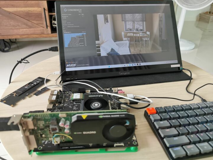
SBC software news – Armbian 24.5.1, DietPi 9.4, and Otii server for the Raspberry Pi 4/5

Qoitech Otii Raspberry Pi 4

There’s been some notable software news for single board computers (SBCs) in the last few weeks with the release of Armbian 24.5.1 Havier with a focus on stability and UX improvement, the release of DietPi 9.4 lightweight Debian distritions for SBCs, and Otii server, the software for Qoitech Arc power supply, meter, and DAQ, has been finally released for the Raspberry Pi 4/5.

Armbian 24.5.1 Havier

Armbian 24.05.1

Armbian announced 24.5.1 Havier on May 25 with bug fixes and improvements as a point release, but also some new boards. Here are some of the highlights.

  • New boards
  • Improve Khadas support
  • Resolve Rockchip patch maintenance nightmare
  • Add functionality to freeze git resources
  • Improve support for Radxa Rock S 0 and test USB and Ethernet
  • Add KDE Neon desktop to Armbian Jammy
  • Add board Bananapi M7 to vendor kernel 5.10 and 6.1
  • Update meson edge to 6.8 kernel
  • Rockchip-rk3308-current: sakura pi rk3308b adds kernel 6.6 and 6.8 support
  • Switch odroidxu4-current kernel to 6.6
  • VIM1S/VIM4: Allow building on arm64 platform
  • VIM1S/VIM4: Add support for eMMC + NVME/USB booting
  • H96-TVbox-rk3566 Board Bring Up
  • Rock 4C+: update and cleanup boot config
  • Enable *NVMe-over-TCP* for rk35xx/rk3588/rockchip64/uefi/wsl
  • Develop build config for board BananaPi M4 Zero
  • Develop and add Ayn Odin2 build config
  • Develop PPA for (patched) aarch64 Chromium
  • And many more shown the full changelog.

As usual, you can download the latest images on the Armbian website with different levels of support: Platinum means the SBC vendor is paying for support, Standard means the Armbian team still works on it since the image is for a relatively popular board, and community supported where motivated users maintain it themselves. Banana Pi and Khadas are the two companies paying for Platinum support.

DietPi 9.4

The release of DietPi 9.4 was announced on May 12 with new images for ROCK 4C Plus, Orange Pi 3 LTS, Radxa Zero 3E/3W, and Orange Pi Zero 2W SBCs.

DietPi 9.4

Some enhancements in DietPi 9.4 include:

  • DietPi scripts do now internally enforce the default umask 0022. Many config and install options rely on this, hence it can cause permission issues.
  • NanoPi R5C – M.2 Modules supports for new images, or when flashing the new bootloader binary via dietpi-config -> Advanced Options -> Update MMC bootloader
  • Orange Pi 3B – Added an option for updating the SPI bootloader via dietpi-config -> Advanced Options -> Update SPI bootloader.
  • ODROID-XU4 – The kernel has been upgraded to Linux 6.6 for this older board.
  • DietPi-CloudShell – On Odroid XU4, when using the CloudShell 2 LCD, during configured auto screen off times, the backlight power of the LCD will be disabled as well, to save energy and avoid still visible black display content.
  • DietPi-Config – Added an option to the LCD display menu to toggle the Odroid XU4 CloudShell 2 LCD.
  • DietPi-Software | Snapcast – 64-bit ARM and Debian Bookworm + Trixie will have the now available packages from Snapcast installed, instead of those from the Debian repository.

You’ll find more changed in the aforelinked announcement. The latest DietPi 9.4 images can be found on the download page for a wide range of SBCs, x86 machines, and some virtual machines.

Otii server for Raspberry Pi 4/5

Qoitech Otii Raspberry Pi 4

Fewer people will know about that one, so I’ll explain what the Otii server is. It’s a program that runs on a host typically Windows, Linux, or macOS to control/manage the Otii Arc Pro or Otii Ace Pro 3-in-1 smart power supply, power meter, and DAQ that is a great developer tool for hardware and software engineers that need to optimize the power consumption of their design, firmware, or app. I had the opportunity to review the Qoitech Otii Arc Pro measuring the power consumption of an ESP8266 board and Raspberry Pi 4 SBC several years ago.

But the latest news is not about using the Raspberry Pi 4 or 5 as a device under test (DUT), but as a server, so you don’t need to waste a more powerful machine or laptop for longer measurement runs. An inexpensive SBC can do the same job. Check out the documentation to get started with the Otii software on Raspberry Pi 4/5 with 8GB RAM (recommended) and a USB or NVMe SSD since microSD cards can quickly degrade with continuous logging.

The post SBC software news – Armbian 24.5.1, DietPi 9.4, and Otii server for the Raspberry Pi 4/5 appeared first on CNX Software - Embedded Systems News.
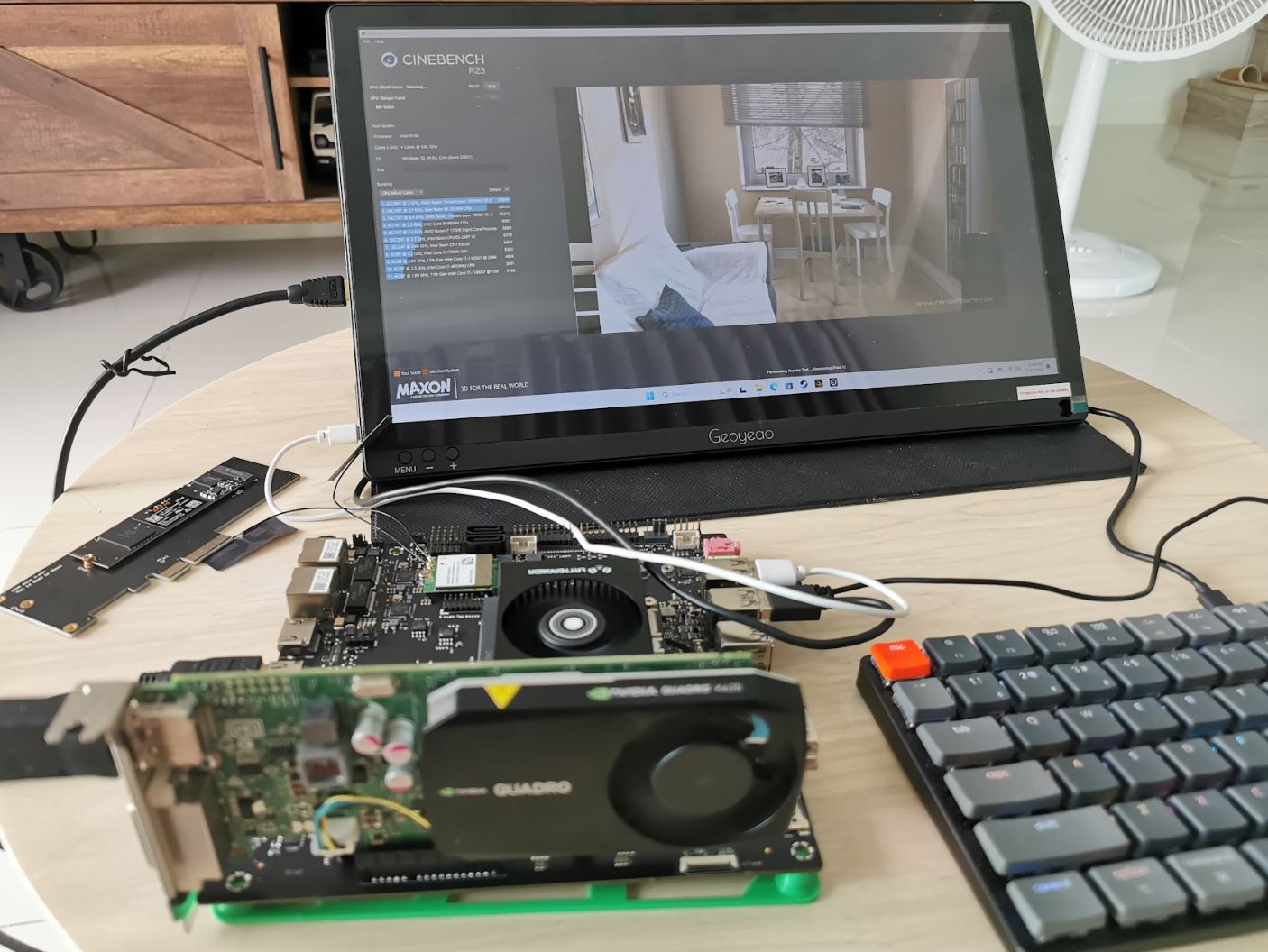
Mekotronics R57 – A Rockchip RK3576 Edge AI fanless mini PC with HDMI input/output, dual GbE, RS232, RS485, DIO…

Mekotronics R57 fanless RK3567 mini PC

Mekotronics R57 is a fanless edge AI mini PC powered by a Rockchip RK3576 octa-core Cortex-A72/A53 SoC with a 6 TOPS NPU, 4GB LPDDR5, a 32GB eMMC flash, and features such as RS485 and dual gigabit Ethernet that makes it suitable for industrial automation.

I initially thought it was a cost-down version of the Mekotronics R58 mini PC that I reviewed with Android 12 as my first ever Rockchip RK3588 device. But while the mechanical design is similar and some of the ports are in the same position, there are some changes with the new model equipped with only one HDMI output, one HDMI input, two GbE jacks, and a terminal block with RS232, RS485, and digital inputs and outputs.

Mekotronics R57 fanless RK3567 mini PC

Mekotronics R57 specifications:

  • SoC – Rockchip RK3576
    • CPU
      • 4x Cortex-A72 cores @ 2.2GHz, four Cortex-A53 cores @ 1.8GHz
      • Arm Cortex-M0 MCU at 400MHz
    • GPU – ARM Mali-G52 MC3 GPU with support for OpenGL ES 1.1, 2.0 and 3.2, OpenCL up to 2.0 and Vulkan 1.1
    • NPU – 6 TOPS (INT8) AI accelerator with support for INT4, INT8, INT16, BF16, and TF32 mixed operations.
    • VPU
      • Video Decoder: H.264, H.265, VP9, AV1, and AVS2 up to 8K @ 30fps or 4K @ 120fps
      • Video Encoder: H.264 and H.265 up to 4K @ 60fps, (M)JPEG encoder/decoder up to 4K @ 60fps
  • System Memory – 4GB LPDDR5
  • Storage – 32GB eMMC flash
  • Video Output – HDMI 2.1 port up to 4Kp120
  • Video Input – HDMI port
  • Audio – 3.5mm audio jack, digital audio output via HDMI
  • Networking
    • 2x Gigabit Ethernet RJ45 ports
    • WiFi and Bluetooth
    • Optional 4G LTE/5G cellular connectivity via mini PCIe socket and SIM card slot
    • 4x antenna holes
  • USB – 1x USB 3.0 port, 2x USB 2.0 ports, 1x USB Type-C port with DisplayPort 1.4 alt mode
  • Expansion – Terminal block with RS232, RS485, 2x digital inputs, 2x digital outputs, 12V, and GND
  • Misc
    • Power button
    • H/L switch for the GPIOs to select “high effective or low effective”
    • Power and Wakeup LEDs
  • Power Supply – 12V DC via power barrel jack
  • Dimensions – 186 x 106 x 33mm
  • Weight – 362 grams
  • Temperature Range – -10 to 75°C

Rockchip RK3567 fanless mini PC with SIM card slot Mekotronics will provide support for Android 14, Ubuntu, Debian, and Buildroot, and the system also supports AI frameworks such as TensorFlow, MXNet, Pytorch, and Caffe through the RKNPU2 toolkit like other recent Rockchip SoCs.

The Rockchip RK3576 fanless edge AI mini PC is available now, and the company told CNX Software that the sample price would be $140 for the default configuration (4GB/32GB). Additional information may be found on the product page. That’s the second hardware platform with RK3576 we’ve covered, the other being the Banana Pi BPI-M5 Pro single board computer.

The post Mekotronics R57 – A Rockchip RK3576 Edge AI fanless mini PC with HDMI input/output, dual GbE, RS232, RS485, DIO… appeared first on CNX Software - Embedded Systems News.
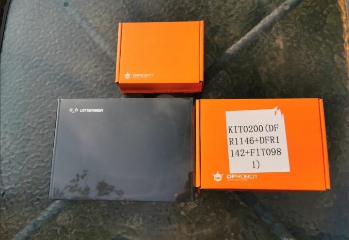
Conexio Stratus Pro – A battery-powered nRF9161 development kit with LTE IoT, DECT NR+, GNSS connectivity (Crowdfunding)

Conexio Stratus Pro nRF9161 IoT prototyping kit

Conexio Stratus Pro is a tiny IoT development kit based on Nordic Semi nRF9161 system-in-package (SiP) with LTE-M/NB-IoT, DECT NR+, and GNSS connectivity and designed to create battery-powered cellular-connected electronic projects and products such as asset trackers, environmental monitors, smart meters, and industrial automation devices.

Just like the previous generation Conexio Startus board based on the Nordic Semi nRF9160 cellular IoT SiP, the new Conexio Stratus Pro board supports solar energy harvesting and comes with a Feather form factor and Qwiic connector for each expansion.

Conexio Stratus Pro nRF9161 IoT development kit

Conexio Stratus Pro specifications:

  • System-in-package – Nordic Semi nRF9161 SiP
    • MCU – Arm Cortex-M33 clocked at 64 MHz with 1 MB Flash pre-programmed MCUBoot bootloader, 256 KB RAM
    • Modem
      • Transceiver and baseband
      • 3GPP LTE release 14 LTE-M/NB-IoT support
      • DECT NR+ ready
      • GPS/GNSS receiver
      • RF Transceiver for global coverage supporting bands: B1, B2, B3, B4, B5, B8, B12, B13, B17, B18, B19, B20, B25, B26, B28, B65 (new), B66, and B85 (new)
  • Storage – 16 KBit I2C EEPROM memory (24CW160T)
  • SIM support – 4FF Nano SIM, optional eSIM, or software SIM
  • Antennas
    • 1x U.FL for LTE-M/NB-IoT antenna
    • 1x U.FL for passive GPS antenna
  • Cellular Data
    • 500 MB of cellular data
    • 250 SMS messages
    • Valid for 10 years, can be reloaded or moved to a new plan
    • Service available in 100+ countries (LTE + NB-IoT)
  • USB – 1x USB Type-C port for USB-to-Serial, DFU, application firmware programming and debugging, battery charging
  • Sensors
    • STMicro LIS2DH 3-axis accelerometer
    • Battery fuel gauge (enabled by nPM1300 PMIC)
  • Expansion
    • Feather-compatible header with 28 programmable GPIO pins
    • QWIIC connector for external peripherals such as a small camera for ML applications
  • Debugging
    • Supports J-Link and CMSIS-DAP-based programmers
    • 10-pin (1.27 mm pitch) mini SWD/JTAG pin connector
  • Misc
    • 2x push buttons (1x reset, 1x programmable)
    • Programmable LED
  • Power Management
    • Voltage Range – 1.8 to 5.5V
    • 2-pin JST connector for LiPo battery
    • Output voltages (via headers) – 1.8V, 3.3V, 5V (VUSB), VBAT
    • SPDT slide switch for turning Stratus Pro on or off
    • Quiescent current of entire board < 9 μA
    • PMIC – Nordic nPM1300
      • 800 mA battery charger
      • Dual 200 mA buck DC/DC regulator
    • Charging IC – Texas Instruments BQ25185
      • Charge inputs: 3V to 18V
      • Supports Li-ion, Li-Poly, and LiFePO4 battery chemistries
  • Dimensions – 66.04 x 25.40 mm
Conexio Stratus Pro pinout diagram
Pinout diagram

While the hardware by itself is interesting, the company also made sure it is ready-to-use out of the box and versatile thanks to integration with a range of software platforms. The board notably comes preloaded with 500 MB of mobile data and 250 SMS messages, valid for 10 years with coverage in more than 100 countries worldwide.

The Conexio Stratus Pro board comes preprogrammed with the open-source MCUBoot bootloader and the company provides a Visual Studio Code Plugin that allows developers to create projects with nRF Connect SDK and Zephyr RTOS with built-in templates. The board works with several cloud platforms including Edge Impulse, Golioth, and Memfault to provide machine learning (e.g. for predictive maintenance), over-the-air (OTA) upgrades, and remote device management solutions. The Status Pro can also connected to the Datacake low-code IoT platform for easy data visualization and dashboard creation. You’ll find documentation to get started on the company’s website and additional resources such as the schematics and firmware on GitHub.

Conexio Stratus Pro comparison table
Comparison table provided by Conexio

Conexio compares the Stratus Pro to other cellular IoT boards in the table above, but strangely, the comparison does not include the company’s earlier Stratus board, maybe because it is phased out…

The company has just launched the Startus Pro nRF9161 IoT development kit on Crowd Supply with a $5,000 funding goal.  Rewards start at $83 for the early bird discount, and the regular price (on Crowd Supply) is $89. Shipping adds $8 to the US, and $18 to the rest of the world, and backers should expect deliveries to start by the beginning of September 2024.

The post Conexio Stratus Pro – A battery-powered nRF9161 development kit with LTE IoT, DECT NR+, GNSS connectivity (Crowdfunding) appeared first on CNX Software - Embedded Systems News.
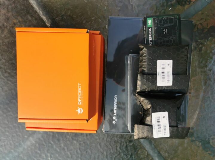
Quectel SG368Z WiFi 5 and Bluetooth 4.2 smart module is built around Rockchip RK3568 SoC

Quectel SG368Z Smart Module

The Quectel SG368Z Smart Module is an all-in-one hardware package built around a Rockchip RK3568 AI SoC that combines computing, graphics, storage, and connectivity in a compact form factor. The  LGA module offers WiFi 5 and Bluetooth 4.2 connectivity, dual gigabit Ethernet networking, various video output options (HDMI, LVDS, RGB, MIPI, eDP), USB, PCIe, and many other features making it suitable for applications like smart homes, wearables, and industrial automation.

Previously we have seen Quectel introduce various communication modules like the Quectel BG95-S5 5G, the  Quectel KG200Z LoRa the Quectel RG255G RedCap IoT Module, and the Quectel CC660D-LS IoT-NTN module, but this is the first time we have seen Quectel release a Smart Module which can be certainly be considered as a SoM in a LGA package.

Quectel SG368Z Smart Module

Quectel SG368Z Smart Module specifications:

  • SoC – Rockchip RK3568
    • CPU – Quad-core Cortex A55 processor at up to 2.0 GHz
    • GPU – Mali G52 GPU with support for OpenGL ES 1.1/2.0/3.2, OpenCL 2.0, Vulkan 1.1
    • VPU
      • 4Kp60 H.264, H.265, VP9, 1080p60 MPEG-4/-2/-1, VP8, and VC1 video decoder
      • 1080p60 H.264/H.265 video encoder
    • AI accelerator – 0.8 TOPS NPU
  • Memory and Storage
    • 2GB+32GB or 4GB+32GB (commercial)
    • 2GB+16GB or 4GB+32GB (industrial)
  • Display interfaces
    • HDMI
    • eDP
    • LVDS
    • MIPI
    • RGB (component video signal)
  • Networking
    • 2x Gigabit Ethernet ports (TI DP83867 Ethernet PHY on RGMII interface)
    • Wi-Fi 5 and Bluetooth 4.2
    • Optional LTE Cat 1/4, 5G, Wi-Fi 6, and GNSS
  • USB – 4x USB 2.0/3.0 interfaces
  • Serial Ports – Multiple industrial UARTs
  • Operating Temperature
    • -10°C to +75°C (commercial)
    •  -40°C to +85°C (industrial)
  • Package – 46.0 x 42.0 x 3.15mm LGA package

The module also features an 8M image signal processing (ISP) and high dynamic range (HDR) video capabilities. Quectel has not yet released detailed specifications comparable to those available for other RK3568-based SBCs like the SBC-3.5-RK3568 or AAEON RICO-3568

Quectel function modules LTE Cat 1 4, 5G, Wi Fi 6, and GNSS
Quectel Function Modules LTE Cat 1/4, 5G, Wi-Fi 6, and GNSS

The new SG368Z Smart Module can easily integrate with Quectel function modules such as LTE Cat 1/4, 5G, Wi-Fi 6, and GNSS making it easy for those who want to build products around these modules.

Regarding software, the Quectel SG368Z Smart Module boasts support for several operating systems including Linux, Android, and OpenWrt. Additionally, it is designed to integrate with Qt components, simplifying the application development process.

Quectel SG368Z Smart Module Development Board

Though Quectel has not yet released details for the SG368Z module itself, they have provided some information about the development board in the “SG368Z Series EVB User Guide”. which is available on the download section of the products page but to get it you need to log in to Quectels website.

As of now, Quectel has not disclosed pricing details for the SG368Z Smart Module, nor have they released the software image files for Linux, Android, or OpenWrt. However, you can find further information about this product in the press release or on the product page on the Quectel website.

The post Quectel SG368Z WiFi 5 and Bluetooth 4.2 smart module is built around Rockchip RK3568 SoC appeared first on CNX Software - Embedded Systems News.
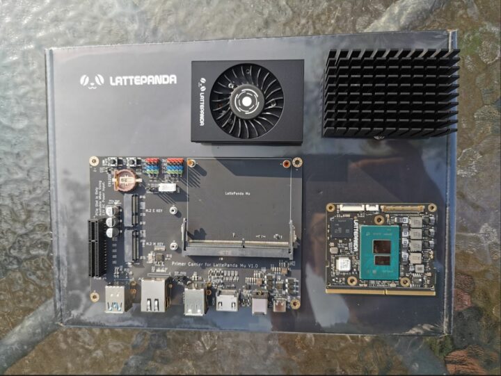
DSTIKE Deauther Watch X is a cheap wireless hacking tool that runs the ESP8266 Deauther firmware

Deauther Watch X worn on wrist

The DSTIKE Deauther Watch X is a Wi-Fi hacking tool that can be used to test wireless networks, powered by the ESP8266 wireless microcontroller and running the open-source Deauther firmware from SpacehuhnTech. It only works on 2.4GHz networks, since 5GHz Wi-Fi is not supported by the ESP8266. It also features a real-time clock module for displaying the time, like an actual watch.

Deauther Watch X worn on wrist

If you are not familiar with the term, a Wi–Fi Deauther is a device that can perform deauth or de-authentication attacks on Wi-Fi networks. It can kick other devices off a Wi-Fi network they are connected to, for learning or other purposes.

The Deauther Watch X is the latest product in the DSTIKE Deauther Watch series from Travis Lin and we previously took a look at DSTIKE ESP32 Watch Development Board. The Watch X development board comes in a wristwatch form factor, uses an ESP8266 module instead of ESP32, and integrates a new charging circuit and power control mechanism.

It is not the best-looking watch but it gets the job done. It is targeted at network enthusiasts and developers looking to test their networks and protect against deauth attacks.

Deauther Watch X development board

DSTIKE Deauther Watch X specifications:

  • Microcontroller – ESP-07 wireless module, ESP8266 32-bit Tensilica microcontroller @ 160 MHz
  • Storage – 4MB flash
  • Antenna Range – 30 to 50m
  • Display – 1.3″ OLED using SH1106 driver
  • Expansion – 8-pin header
  • Battery/Power
    • Battery Capacity – 500mAh
    • Work time – 5 to 6 hours
    • 500 mA charging current
    • Charging LED indicator – RED: Charging, GREEN: Full
    • Power Switch – Press for 2 seconds to turn ON/OFF
    • Protection –  short, overcharging, overdischarging, temperature
  • Misc – Up, Down, and Select Buttons, Buzzer, external FPC antenna connector
  • Dimensions – 60 x 50 x 25mm
  • Weight – 62g

The open-source Deauther firmware comes pre-installed on the Watch X. The Deauther is advertised for educational and development use but it is easy to see how it can be used for malicious purposes. Note that using a deauther on a network that you don’t own is illegal in most countries and can lead to prosecution. The ESP8266 Deaither firmware does not work on ESP32 which must be why a new version of the SDTIKE watch has been created.

The DSTIKE Deauther Watch X is priced at $39 on Tindie and the DSTIKE website. The firmware is open-source and you can build your own deauther by following the tutorial on the developer’s website.

The post DSTIKE Deauther Watch X is a cheap wireless hacking tool that runs the ESP8266 Deauther firmware appeared first on CNX Software - Embedded Systems News.
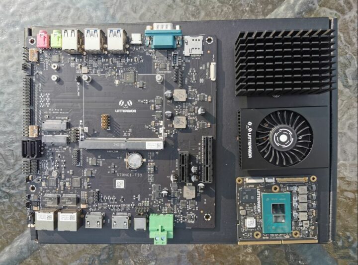
High-Performance Edge Computing with PICMG COM-HPC: A Virtual Event Series (Sponsored)

COM-HPC Mini Academy

Doug Sandy is the CTO of PICMG, an industry consortium focused on developing open and modular computing specifications. He, along with dozens of member companies who participated in the development of the upcoming COM-HPC specification, believes that engineers building edge systems need new hardware.

“Between converged network rollouts and advances in AI, the hardware requirements for edge computing have changed,” Sandy says. “Modern edge workloads need a combination of high-end compute, managed power consumption, and low-latency data transmission.”

COM-HPC Mini Academy

These merging requirements led PICMG to pursue a new standard for high-performance computing. The result is COM-HPC, a computer-on-module specification that brings unprecedented computing power and I/O bandwidth to resource-constrained applications.

First ratified in 2021, COM-HPC has expanded to address various use cases. Most recently, COM-HPC Mini was created to address small form factor applications. “COM-HPC Mini introduces a credit-card-sized form factor with features like expanded connectivity support, efficient thermal management, and soldered memory,” explains Sandy.

COM-HPC Mini complements the consortium’s well-established COM Express specification but introduces a number of major advances. To help designers take advantage of the new capabilities, PICMG is launching the free COM-HPC Mini Academy. This four-part series will teach developers everything they need to know about the specification.

Session 1: What’s New in COM-HPC?

The first Mini Academy Session, co-hosted by representatives from congatec and Samtec, provides an update on COM-HPC and how it can help organizations transform their edge infrastructure. Alongside updates to the COM-HPC specification family, the session will explore potential for PCIe Gen 6 support and Functional Safety (FuSa) capability.

Session 2: Introducing COM-HPC Mini

COM-HPC Mini development board

Co-presented by Richard Pinnow of ADLINK and Christian Engels of Avnet Embedded, the next session will detail how COM-HPC Mini provides system architects greater speed and performance in a smaller form factor. Participants can expect a review of the new specification’s electromechanical features, followed by demonstrations of how those features can be leveraged in far edge mobile and battery-powered use cases such as AMRs, HMIs, drones, and robotic controllers.

Session 3: Exploring the COM-HPC Mini Design Guide

Presented by Kontron’s Peter Hunold, this session introduces an updated Carrier Design Guide developed specifically for the COM-HPC Mini specification. Participants will be given an overview of how the COM-HPC Design Guide has changed from previous versions. The session will also demonstrate how to design in advanced signals such as multiplexed USB 4.0 and quickly and efficiently produce Gerber files that define lasting COM-based systems.

Session 4: A Multi-Vendor Outlook Panel

Co-hosted by several of the suppliers responsible for developing the COM-HPC Mini specification, this panel discussion will field questions from attendees about designing and deploying the new standard. Anticipated discussion topics include the differences between COM Express and COM-HPC, best practices for designing COM-HPC Mini into real-world applications, as well as insights into PICMG’s technology roadmap.

Register Now to Begin Your Journey

The COM-HPC Mini Academy kicks off on Tuesday, June 4 at 7:00 PDT/14:00 UTC. Recordings of the sessions will be available on-demand for those unable to attend the live event.

Don’t miss out on this opportunity to learn about the next evolution in edge computing.

REGISTER NOW

The post High-Performance Edge Computing with PICMG COM-HPC: A Virtual Event Series (Sponsored) appeared first on CNX Software - Embedded Systems News.
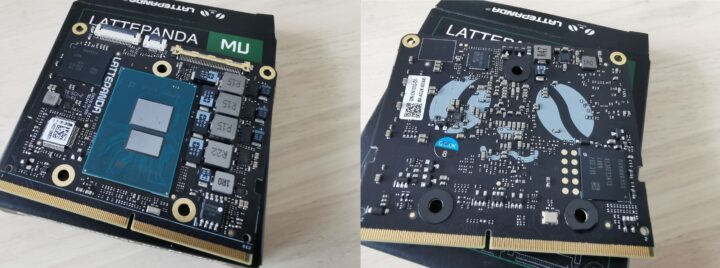
TOOCAA L2 Review – A fully enclosed 20W laser engraver & cutter with a focus on safety

TOOCAA L2 review 20W laser engraver cutter

TOOCAA L2 is a fully enclosed laser engraver and cutter with a 10W or 20W laser module using orange acrylic covers and various sensors for additional safety. The laser module complies with Class 1 Laser Safety certification and the engraving and cutting machine works with a range of materials suitable for creators who want to cut or/and carve workpieces or manufacture high-resolution parts.

The company sent us a sample of the TOOCAA L2 with a 20W laser model, an air assist pump, a honeycomb plate, and a few consumables for review. We’ll first go through an unboxing of all items and assembly, before testing the laser engraver and cutter under various scenarios.

TOOCAA L2 20W review

TOOCAA L2 unboxing

The review kit we received includes three packages from TOOCAA. Each package contains various components. with foam drilled into shape to support each part and right-angled cardboard along all four corners of the package to prevent damage during transportation. Let’s open those to find out what we’ve got…

TOOCAA L2 20W Kit Unboxing
The large box comes with the TOOCAA L2 laser engraver.

TOOCAA L2 20W unboxing review
TOOCAA L2 20W accessories user manual

TOOCAA L2 20W frame
The machine has a pre-assembled frame ready for use.

The laser module features diodes that emit light using electricity with a wavelength of 455 nanometers +- 5 nanometers. It uses 24V direct current power, 20 Watts of power, and comes with a system to protect against laser beams and a blue light filter.
20W laser module
There’s also a retractable aluminum foil exhaust duct to get rid of fumes through your window or other opening.

exhaust for laser engraver and cutter
The enclosure is comprised of six orange clear acrylic sheets, each 5 millimeters thick, and which we will need to attach to the machine.

TOOCAA L2 20W acrylic enclosure
A toolbox includes a 4GB microSD card, a USB Drive Lock, a USB Type-C cable, a screwdriver, some hex keys, a fixed-focus bar, and other accessories.

TOOCAA L2 tools

While the TOOCAA L2 is a fully enclosure laser engraver, the company still included safety goggles with the kit for eye protection.

protection glasses
The machine is powered by a 24V/3A adapter that takes 100-240V AC input and outputs through a 5.5mm DC jack.

TOOCAA L2 20W packing list
Packing list provided by TOOCAA
24V 5A power adapter for TOOCAA L2 20W
24V/5A (120W) power supply

TOOCAA consumable parts pack
The TOOCAA “consumable parts pack” comes with 1/8″ Basswood plywood, an aluminum sheet, two color aluminum engraving army tags, and one stainless steel army tag.

Let’s now open another package with the honeycomb working panel.

Honeycomb Panel laser engraver

Key features:

  • Dimensions – ​​320 x 320 x 22 mm  millimeters
  • Used to place materials for cutting or engraving
  • Comes with an aluminum sheet (320 x 320 x 1mm) to protect the table/desk
  • Materials – Steel and aluminum

The latest package comes with the air assist kit for the TOOCAA L2 machine.

TOOCAA air assist kit
The TOOCAA air assist kit creates a continuous flow of compressed air to blow away the debris and fumes that may occur during the laser engraving or cutting process. It protects the lens and extends the life of the laser module. It also improves the quality of the engraving or cutting job.

Key features

  • Maximum airflow – 30 liters/minute
  • Noise – 40 dB
  • 24V/1A power adapter
24V 1A power adapter
Power adapter

TOOCAA L2 specifications

  • Spot size – 0.27 x 0.15 mm
  • Working area – 415 x 395 mm
  • Engraving speed – Up to 400mm/s
  • Input voltage – 24V/5A
  • Supported software – LightBurn or LaserGRBL
  • Operating System –  Windows, MacOS, or Linux
  • Connection method – USB Type-C or microSD card
  • Dimensions – 645 x 617 x 306 mm
  • Weight – 13kg
  • Machine material – Aluminum alloy
  • “Smart Enclosure material” – Acrylic plate and aluminum alloy

Main types of laser engraving machines

  1. Diode Laser Engravers – These are optoelectronic devices that convert electrical energy into light. This results in a coherent light of high intensity. which is used to carve objects. This type of machine is becoming very popular with hobbyists due to its small price and affordable pricing.
  2. CO2 Laser Engravers – These machines use a beam of carbon dioxide to penetrate materials. The efficiency is low and suitable for engraving and cutting non-metallic materials such as paper, cloth, leather, acrylic, and wood.
  3. Fiber Laser Engravers – Fiber laser machines create a powerful laser beam by sending a high-intensity light down a fiber optic cable. It is generally doped with ytterbium to release high-capacity energy in the form of photons.

Before buying a laser engraving machine you need to know what material you will be working with. For example, carbon dioxide laser machines are ideal for clear acrylic, and diode laser engravers are suitable for woodworking. But engraving metal requires faster speed. Is it necessary to use a galvanic or fiber laser? For beginners, a desktop diode laser engraver seems more suitable because the machine is lightweight, easy to use, and requires little maintenance. Carbon dioxide laser and fiber laser machines require more maintenance.

TOOCAA L2 highlights and tips

Safety features

The TOOCAA L2 is an all-in-one package, assembly is straightforward, and you can use the machine a few minutes after you receive it. There’s very little risk the machine will not work due to user errors after assembly because all the main parts are preassembled. The XY axis movement is provided by slide rails and belts. The laser engraver features two stepping motors using ball-bearing wheels and high-quality aluminum profile rails.

The TOOCAA L2 also focuses on user safety with a fully enclosed design protecting the user from the laser and fumes thanks to an exhaust pipe and fan. Furthermore, the laser module passed Class 1 Laser Safety certification.

TOOCAA L2 20W installation with exhaust

Some safety highlights:

  • Exhaust Fan – The smoke produced during the cutting process can be released through a window or air purifier making the system safer and healthier to use.
  • Tilt Detection – A gyro tilt and collision warning system stops the machine and laser module automatically when the angle between the machine and the horizontal plane is over 15 degrees.
  • Flame Detection – The flame detection alarm will stop the laser output when the machine or workpiece is in flames, and the laser module will automatically return to the starting point. The machine needs a restart in this state.
  • USB Drive Lock – It is the equivalent of a car key for your laser engraver. The device can only be turned on if the USB Drive Lock is inserted into the USB Type-A port in order to prevent children from using the machine without adult supervision and eliminate associated safety risks.

Supported materials and laser power and speed settings

The TOOCAA L2 laser engraver and cutter can cut or engrave various materials requiring different laser power and speed settings. The above table lists recommended parameters for different materials, but note these values are for reference only due to variation for a given material. Higher power or slower speeds generally produce deeper results, while lower power or faster speeds produce shallower results.

Laser PowerEngraving SizeProcessing ModeMaterialThickness (mm)Power (%)/Speed (mm/min)/Pass
10W395mm*415mmEngravingBasswood240 / 3000 / 1
10W395mm*415mmEngravingBamboo540 / 3000 / 1
10W395mm*415mmEngravingKraft paper0.225 / 3000 / 1
10W395mm*415mmEngravingRed card paper0.225 / 3000 / 1
10W395mm*415mmEngravingRed felt0.815 / 3000 / 1
10W395mm*415mmEngravingBrown leather0.6520 / 3000 / 1
10W395mm*415mmEngravingBlack acrylic4.550 / 3000 / 1
10W395mm*415mmEngravingAnodized aluminum3100 / 200 / 1
10W395mm*415mmEngravingStainless steel2100 / 500 / 1
10W395mm*415mmEngravingWhite Tile Painted Black695 / 3800 / 1
10W395mm*415mmCuttingBasswood2100 / 350 / 3
10W395mm*415mmCuttingBasswood4100 / 200 / 1
10W395mm*415mmCuttingBasswood5100 / 150 / 1
10W395mm*415mmCuttingBasswood8100 / 230 / 3
10W395mm*415mmCuttingBamboo5100 / 230 / 3
10W395mm*415mmCuttingBlack acrylic4.5100 / 120 / 2
10W395mm*415mmCuttingKraft paper0.2100 / 3500 / 1
10W395mm*415mmCuttingRed card paper0.2100 / 3500 / 1
10W395mm*415mmCuttingRed felt0.8100 / 3500 / 1
10W395mm*415mmCuttingBrown leather0.65100 / 1500 / 1

Adjusting the laser focus

Just like other laser engravers we’ve reviewed the laser focus must be adjusted.  A few laser engraving machines support auto-focus, but the TOOCAA L2 required manual focus like many of its peers. Four main steps are required:

  1. Place the workpiece to be carved
  2. Unlock the laser head
  3. Move the focus key down so that it hits the target.
  4. Lock the laser head

laser module lock unlock

TOOCAA L2 20W focus adjustment
Remarks

  • Please make sure the focal length of the laser module is correct and the lens of the laser module is clean. We can clean it with a dust-free cloth moistened with alcohol when the laser is turned off.
  • The focus distance between the laser head and the target will be approximately 1 centimeter.
  • The work table should be protected by using steel sheets or other materials that the laser cannot easily penetrate.

Preparing the TOOCAA L2 for use and software

Please turn on the machine in the following order:

  1. Turn on the air pump
  2. Turn on the exhaust fan
  3. Turn on the switch on the laser cutting machine.

TOOCAA L2 first try
Steps before starting laser engraving

  1. Load the file into the laser cutter
  2. Place the workpiece and set the starting position for cutting or engraving
  3. Setting the focus distance
  4. Close the machine cover.

Laser engraving software

The TOOCAA L2 laser cutter is compatible with the two most popular laser software used by connecting the TOOCAA L2 control board to a computer with a USB Type-C cable:

  • Lightburn software to control the laser engraving and cutting machine, and design and edit work pieces. It’s compatible with Windows, macOS, and Linux. Visit the Lightburn official website to download a free trial version for 30 days.
  • LaserGRBL is free and open-source software for hobby and professional use released un a GPL v3.0 license. You can download LaserGRBL for Windows on the official website.

Getting started with the TOOCAA L2

TOOCAA provides a file for a  “Do Not Disturb” sign in the 4GB microSD and various documents as follows:

  • TOOCAA L2 User Guide V1.1.pdf – User manual for the laser engraver
  • TOOCAA L2.lbdev – User manual for LightBurn with optimized parameters for the TOOCAA L2
  • TOOCAA_L2_Case(10W) V1.0.gc” – G-code sample file for cutting and graving a “Do Not Disturb” sign.

TOOCAA L2 20W microSD card drivelock

Here are the main steps to get started:

  • Insert the USB Drive Lock
  • Connect the power cord to the machine.
  • Insert the microSD card with a work file (e.g.TOOCAA_L2_Case(10W) V1.0.gc)
  • Turn on the machine switch.
  • Press the button on the front of the machine once to move the laser head to the starting point of the workpiece.
  • Press the button on the front of the machine twice to start the laser engraving process
  • After a few minutes, you will get a “Do Not Disturb Sign” sign to attach to your room doorknob.

TOOCAA L2 Front Button

Remarks: You will want to wear the provided green safety goggles to look at the machine while the machine is operating to protect your eyes from the blue light coming from laser diodes.

TOOCAA L2 20W sample do not disturb sign

Material – 3mm plywood
Dimensions: 17.5 x 6.5 cm
Estimated Time: 18 minutes

You can watch the process (accelerated five times) in the video embedded below.

Detailed testing of the TOOCAA L2 laser engraving and cutting machine

Laser power and speed tests

The first “greyscale test” will make the machine engrave plywood with a sample image with different levels of grey from 5% to 100%. We will be using LaserGRBL for all remaining tests in this review.

TOOCAA L2 cnxsoft test pattern

Parameters:

  • Material – 3mm plywood
  • Dimensions – 11 x 8.3 cm
  • Engraving Speed – 1,500 mm/minute
  • Power – 0 – 40%
  • Laser Mode – M4 – Dynamic Power
  • Image resolution – 300 dpi
  • Estimated Time – 16 minutes

TOOCAA L2 cnxsoft test pattern laser engraver

You can watch the engraving for the greyscale test in the video below accelerated by three times.

The next sample is a similar test with varying engraving speeds from 1,000 to 4,000 mm/minute.

LaserGRBL laser power speed test pattern
Parameters:

  • Material – 3mm plywood
  • Dimensions – 10 x 7 cm
  • Engraving Speed – 1,000 to 4,000 mm/minute
  • Power – 0 – 40%
  • Laser Mode – M4 – Dynamic Power
  • Quality – 8 lines/mm
  • Estimated Time – 30 minutes

TOOCAA L2 Laser GRBL power speed sample

We’ve also shot a video accelerated by 5 times to show the engraving process in action.

TOOCAA L2 cutting test

The sample below tests cutting at different speeds and with one to four passes.

LaserGRBL cutting test
Parameters:

  • Material – 3mm plywood
  • Dimensions – 7 x 6 cm
  • Engraving Speed – 200 to 1,000 mm/minute
  • Power – 80%
  • Laser Mode – M3 – Constant Power
  • Estimated Time – 5 minutes


TOOCAA L2 20W cutting test

This test shows the TOOCAA L2 can cut 3mm plywood at 80% laser power under the following conditions.

  • One pass at 200 mm/minute
  • Two passes at 200, 400, and 600 mm/minute
  • Three passes at 200, 400, 600, and 800 mm/minute
  • Four passes at 200, 400, 600, 800, and 1000 mm/minute

The demo video below is accelerated by two times. The air assist pump helps deliver good quality cuts without burned-out areas.

Accuracy test

The small 20x20mm test pattern below is used to check the accuracy of the machine, the thickness of the laser spot, and the laser focus.

LaserGRBL accuracy test patternParameters

  • Material – 3mm plywood
  • Dimensions – 24 x 22 cm
  • Engraving Speed – 1,000 mm/minute
  • Power – 0 – 100%
  • Laser Mode – M4 – Dynamic Power
  • Estimated Time – 1 minute

TOOCAA L2 20W accuracy test pattern

The video for the accuracy test is shown in real-time.

Shake test

We’ll test the reliability/repeatability of the machine by engraving a small reference cross. Once the cross is engraved, the machine is set to move the laser module in erratic movements along one axis for a couple of minutes and then returns to the original position to engrave the cross again. If the test is successful, the first and second crosses will overlap perfectly. We ran the test twice: once for the X-axis, and another time for the Y-axis, and the results are all good as you can see in the photo and videos below.

TOOCAA L2 20W shake test

Parameters for the X-axis shake test

  • Length – 300 mm
  • Speed limit – 4000mm/s
  • Engraving speed: 1000mm/m and power: 100%
  • Estimated Time – 3 minutes

Parameters for the Y-axis shake test

  • Length – 200 mm
  • Speed limit – 4000mm/s
  • Engraving speed: 1000mm/m and power: 100%
  • Estimated Time – 1 minute 30 seconds

The X-axis shake test can be seen in the video below in real-time.

Same thing for the Y-axis.

If your engraving machine fails this test, check or do the following:

  • The machine does not slip on the table due to vibration during operation
  • The table and workpiece did not vibrate during the test
  • Adjust the drive belt for proper tension
  • Tighten screws and nuts properly
  • Make sure the laser module can move freely along its axes without mechanical friction
  • Make sure the wires do not act as a barrier to movement
  • Try to lower the engraving speed if all these conditions are met, but the machine still does not pass this test.

Summary of TOOCAA L2 test results

We have tested the machine with 4 tests:

  • Laser power and speed test
  • Cutting test
  • Accuracy test
  • Shake Test

The TOOCAA L2 20W laser cutting and engraving machine has passed all 4 tests to acceptable levels.

TOOCAA L2 20W all samplesTOOCAA L2 open cover

Precautions while using a laser cutting machine

Some materials should not be cut with a laser machine such as all kinds of materials that contain PVC because

  • They will emit toxic gases that are dangerous to living things
  • The fumes will adhere to the lens of the laser cutter shortening the lifespan of the lens

One more danger is the risk of fire when using flammable materials or if the user is not actively monitoring the cutting of a workpiece. If a fire has been ignited follow the steps below:

  1. Open the machine cover
  2. Find a cloth and slap the fire to extinguish it
  3. Use a dry chemical fire extinguisher as the last resort since it may cause damage to the laser-cutting machine.

TOOCAA L2 review 20W enclosed laser engraver cutter

Conclusion

ELECFREAKS is a company founded in 2011 primarily engaged in Arduino peripherals and maker hardware, but they introduced the TOOCA brand (now TOOCAA) for laser engraver and cutting machines in 2022, and we reviewed the TOOCA L1 5W laser engraver at that time.

The TOOCAA L2 is available with a 10 Watts or 20 Watts laser module, and our sample was equipped with the latter. The machine is designed with a strong structure made of an aluminum frame with X and Y axes and ships mostly pre-assembled and ready to use after installing the orange clear acrylic covers. The TOOCAA L2 heavily focuses on safety, as besides being a fully enclosed laser engraving and cutting machine, it also features various safety measures such as an exhaust fan, a USB drive lock to prevent children from starting the machine without adult supervision, and tilt and flame detection mechanisms to stop the machine in case of unexpected events such as falls or fires.

The laser engraver and cutter allows users to create high-definition cutting and engraving workpieces such as carved designs on containers, name tags, rubber stamps, frames for Buddha amulets, and more.

We’d like to thank TOOCAA for sending the TOOCAA L2 20W laser engraver & cutter for review along with various accessories. The model reviewed can be purchased on the TOOCAA website for $1,099, while the 10 Watts model starts at $849. Note that the price does not include the air assist kit and the honeycomb working table which are available separately for $129.99 and $69.99 respectively.

CNXSoft: This review is a translation of the original article on CNX Software by NinePhon Kongangkab, edited by Suthinee Kerdkaew.

The post TOOCAA L2 Review – A fully enclosed 20W laser engraver & cutter with a focus on safety appeared first on CNX Software - Embedded Systems News.
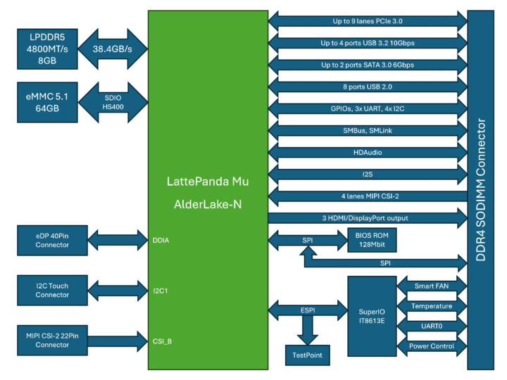
Espressif releases Arduino ESP32 Core 3.0.0, but PlatformIO support is in doubt

Arduino IDE ESP32-C6 boards

We previously noted the ESP32 Arduino Core 3.0.0 Alpha release added support for ESP32-C6 and ESP32-H2 among other changes. The good news is that Arduino ESP32 Core 3.0.0 is now considered stable, and was released a few days ago based on the ESP-IDF 5.1.4 framework. Users of the Arduino IDE can use it straight away, but as we’ll discuss in more detail below it’s unclear whether PlatformIO will be (officially) supported.

ESP32-C6 ESP32-H2 ESP32 Arduino Core 3.0.0

There have been many changes since we wrote about the Alpha2 release in November 2023 with 327 commits from 96 contributors. Some of the most recent changes (compared to RC3) include:

  • Updated ESPDuino with extra options (CPU freq and Partition)
  • Add support for WeAct Studio ESP32C3
  • Attach ETH events at the correct place
  • Enable the possibility to use SPI ETH with only 4 wires
  • Fix ETH.end()
  • Fix ETH.stop() with IDF SPI
  • Nano ESP32: delete programmer.default entry (on main) due to unintended consequences for CLI users
  • Update Kconfig.projbuild to fix LittleFS selective compilation
  • Fixed outdated function signature (ledcWrite)
  • Remove masking for ADC channel number
  • Add GPIO pin mappings for M5Stack CamS3 Unit and select OPI PSRAM by default
  • Provide a default TAG name for USE_ESP_IDF_LOG logging macro
  • Update merge_package.py to use packaging.version instead of the deprecated distutils.version

You’ll find the release on GitHub for installation in the Arduino IDE just as we did for the Alpha2 release. More ESP32-C6 and ESP32-H2 boards are now supported out of the box, since last time I tried there were only two ESP32-C6 boards and one ESP32-H2 board…

Arduino IDE ESP32-C6 boards

That’s great for users relying on the Arduino IDE, but some prefer working with PlatformIO, and there’s currently an open issue on PlatformIO about support for Arduino ESP32 Core v3.0.0  which may never be officially supported:

The ESP32 Core for Arduino 2.x is the most recent major version currently recommended for use with PlatformIO. The decision to discontinue support was made by the Espressif company, as indicated in their official statement

That’s a long thread, but there seem to be some ongoing commercial discussions between Espressif Systems and PlatformIO developers that are not resolved yet:

[…]
The current supported version is Arduino Core v2.x for ESP32. Our collaboration with Espressif, including discussions about renewal, is ongoing. It’s worth noting that we have @VojtechBartoska, a project manager from Espressif, in this thread. We’re all working together to ensure you receive the best features and support. We’ll keep everyone posted on any updates to ensure a smooth continuation of our services.

[…]

PlatformIO is a commercial open-source project. In the past, it used to be a paid service before 2020, following a business-to-consumer (B2C) model. Unexpectedly, PlatformIO gained widespread popularity among millions of developers globally. Consequently, we shifted our strategy to make powerful tools for professional embedded development freely accessible to everyone.

The active development and maintenance of PlatformIO, along with its infrastructure, are now supported by technology partners dedicated to delivering an excellent developer experience. Espressif was one such partner, and we appreciate their long-standing collaboration.

Currently, Espressif has ceased support for new products in PlatformIO, but rest assured, we are committed to providing support for existing Espressif products integrated before this change, as per our technology licensing policy. Your projects won’t face disruptions, and services will continue as usual.

Those messages are from the end of November 2023, but PlatformIO still does not support the Arduino ESP32 3.x release as of now (June 1, 2024). Having said that one user apparently managed to make PlatformIO work with their ESP32-C6 board using the following JSON file:

{
  "build": {
    "core": "esp32",
    "f_cpu": "160000000L",
    "f_flash": "80000000L",
    "flash_mode": "qio",
    "mcu": "esp32c6",
    "variant": "esp32c6"
  },
  "connectivity": [
    "wifi"
  ],
  "debug": {
    "openocd_target": "esp32c6.cfg"
  },
  "frameworks": [
    "arduino",
    "espidf"
  ],
  "name": "Espressif ESP32-C6",
  "upload": {
    "flash_size": "4MB",
    "maximum_ram_size": 327680,
    "maximum_size": 4194304,
    "require_upload_port": true,
    "speed": 460800
  },
  "url": "https://docs.espressif.com/projects/espressif-esp-dev-kits/en/latest/esp32c6/esp32-c6-devkitm-1/index.html",
  "vendor": "Espressif"
}

But it’s unclear whether all features will work, as another user chimed in:

Yep, for the c6 just the entry arduino needs to be added. Anyways C6 does not work “out of the box”. The needed changes to support C2, H2 and C6 are not so many 😉

We’ll have to see how it goes. So it’s possible to use the new Arduino ESP32 Core 3.0.0 with Platform.io with some effort, but if the companies don’t come to an agreement soon, the long-term future of PlatformIO for ESP32 boards is uncertain. Arduino ESP32 Core 2.x is still supported in PlatformIO, so no issues here for existing boards and projects.

Thanks to Hedda for the tip.

The post Espressif releases Arduino ESP32 Core 3.0.0, but PlatformIO support is in doubt appeared first on CNX Software - Embedded Systems News.
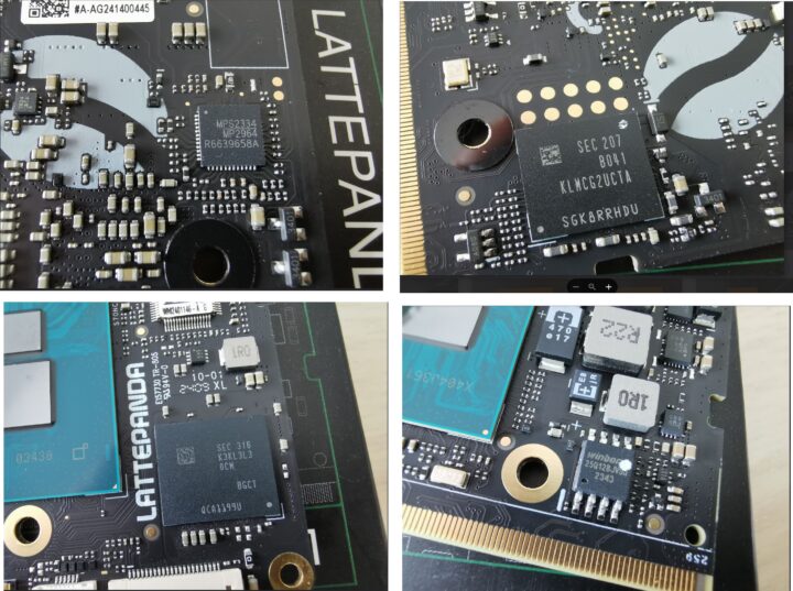
M5Stack CoreS3 SE cost-down ESP32-S3 IoT controller features a 2-inch touch display, a microSD card slot, a speaker, two microphones

M5Stack CoreS3 SE ESP32-S3 IoT controller

The M5Stack CoreS3 SE, also called M5CoreS3 SE, is a cost-down version of the M5Stack CoreS3 IoT controller based on the ESP32-S3 wireless microcontroller with a 2-inch capacitive touch display, a microSD card slot, a USB-C port, a speaker, two microphones, and one Grove connector for expansion.

The M5Core S3 SE loses the DIN Base so the associate features are gone and DIN rail mounting is not possible by default anymore. That also means the M5Stack CoreS3 SE controller is about twice as thin, and the color is also different (medium grey vs black grey). Major internal changes include the removal of the camera and the three sensors found in the original model.

M5Stack CoreS3 SE ESP32-S3 IoT controller

M5Stack CoreS3 SE specifications with highlights in bold and strikethrough showing differences against the CoreS3 model:

  • Wireless MCU – Espressif Systems ESP32-S3FN16R8
    • CPU – Dual-core 32-bit Xtensa LX7 microcontroller with AI vector instructions up to 240MHz, RISC-V ULP co-processor
    • Memory – 512KB SRAM, 8MB PSRAM
    • Storage – 16MB flash
    • Connectivity 2.4GHz WiFi 4 (802.11b/g/n), Bluetooth 5.0 BLE + Mesh,
  • Antenna – Internal “3D” antenna
  • Storage – MicroSD card slot
  • Display – 2-inch display with 320×240 resolution via ILI9342C driver, capacitive touch support
  • Camera – 0.3MP VGA camera @ 30 fps using GC0308 CMOS sensor
  • Audio
    • 1W speaker connected to AW88298 I2S power amplifier chip
    • Dual microphones connected to ES7210 audio decoding chip
  • USB – 1x USB Type-C port
  • Sensors (none)
    • LTR-553ALS-WA proximity sensor
    • BMI270 6-axis gyroscope and accelerometer
    • BMM150 magnetometer
  • Expansion
    • 30-pin female header connected to DIN base with
      • 4-pin GPIO Grove connector
      • 4-pin UART Grove connector
    • 4-pin I2C Grove connector
  • Misc
    • Power and Reboot buttons
    • Power switch
    • BM8563 RTC
  • Power Supply
    • 5V via USB Type-C port
    • 9V-24V DC input via DC jack (previously in DIN Base)
    • Built-in 3.7V/500mAh battery (previously in DIN Base)
    • AXP2101 power management chip
  • Power consumption
    • Battery
      • Standby mode: 4.2V/104.64uA
      • Active mode: 4.2V/109.67mA
    • USB power supply – 5V/166.27mA while active
  • Dimensions – 54x54x16 mm; DIN rail mountable; M3 mounting screws
  • Weight – 73.3 grams 38.4 grams

M5Stack CORES3 SE

ESP32-S3 IoT controller USB-C microSD card Grove connector

The M5Stack CoreS3 SE remains programmable with the Arduino IDE or UIFlow visual programming tool, and users can reuse the Arduino library for the CoreS3 available on GitHub as well as some of the Arduino sketches. As one would expect, the code samples making use of the camera and sensors won’t work… Further technical details can be found on the documentation page.

I first found the M5Stack CoreS3 SE on the company’s Aliexpress store where it is sold for $38.90 plus shipping, but you’ll also find it on the M5Stack shop for $38.60. For reference, the original M5Stack CoreS3 IoT controller sells for $59.90, so the discount is significant if you don’t need any of the extra features.

The post M5Stack CoreS3 SE cost-down ESP32-S3 IoT controller features a 2-inch touch display, a microSD card slot, a speaker, two microphones appeared first on CNX Software - Embedded Systems News.
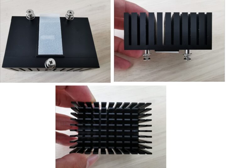
Radxa Fogwise Airbox edge AI box review – Part 1: Specifications, teardown, and first try

Radxa Fogwise Airbox review

Radxa Fogwise Airbox, also known as Fogwise BM168M, is an edge AI box powered by a SOPHON BM1684X Arm SoC with a built-in 32 TOPS TPU and a VPU capable of handling the decoding of up to 32 HD video streams. The device is equipped with 16GB LPDDR4x RAM and a 64GB eMMC flash and features two gigabit Ethernet RJ45 jacks, a few USB ports, a speaker, and more.

Radxa sent us a sample for evaluation. We’ll start the Radxa Fogwise Airbox review by checking out the specifications and the hardware with an unboxing and a teardown, before testing various AI workloads with Tensorflow and/or other frameworks in the second part of the review.

Radxa Fogwise Airbox review

Radxa Fogwise Airbox specifications

The specifications below come from the product page as of May 30, 2024:

  • SoC – SOPHON SG2300x
    • CPU – Octa-core Arm Cortex-A53 processor up to 2.3 GHz
    • VPU
      • Decoding of up to 32x 1080p25 channels with H.265/H.264
      • Full processing of 32x 1080p25 channels with decoding and AI analysis
      • Encoding of up to 12x 1080p25 channels with H.265/H.264
      • JPEG up to 1080p600 (no typo, that’s 600 FPS) up to 32768 x 32768
      • Video post-processing such as image CSC, Resize, Crop, Padding, Border, Font, Contrast, and Brightness adjustments.
    • TPU – Tensor Processing Unit with up to 24 TOPS (INT8), 12 TFLOPS (FP16/BF16) and 2 TFLOPS (FP32) with support for TensorFlow, Caffe, PyTorch, Paddle, ONNX, MXNet, Tengine, and DarkNet
  • System Memory – 16GB LPDDR4X
  • Storage
    • 64GB onboard eMMC flash
    • M.2 M Key connector for 2230 NVMe SSD
    • MicroSD Card slot
  • Networking
    • 2x Gigabit Ethernet ports
    • Optional WiFi and Bluetooth via M.2 E Key module
  • USB
    • 2x USB 3.0 host ports
    • 1x USB Type-C Debug UART port
  • Power Supply – 20V via USB Type-C port, at least 65W
  • Dimensions – 104 x 84 x 52mm (metal case with active cooling)
  • Temperature Range – 0°C to +45°C
  • Compliance Certification – FCC / CE

The specifications and design are almost exactly the same as the Firefly AIBOX-1684X, but except for the SOPHON BM1684X (32 TOPS) used instead of the SOPHON SG2300x (24 TOPS), and the two M.2 sockets that don’t seem to be available in the Firefly AI box. At the time of the Firefly article (April 2024), I was told that “SG2300X supports open-source generative AI, while the BM1684X does not”, but it appears both chips are interchangeable for more on that below…

Based on the documentation, the Radxa Fogwise Airbox AI micro-server runs the CasaOS lightweight operating system offering a private cloud storage solution for home users. The company also offers a “Radxa Model Zoo” with ResNet-50, YOLOv5-det, YOLOv8-seg for object detection, recognition, and segmentation, and provides instructions to run LVMs or LLMs such as Stable Diffusion and Llama-3.

Fogwise “BM168M” unboxing

The Fogwise Airbox ships in a retail box that reads “Fogwise BM168M Edge Micro-Sever for AI”. Besides the typo, I was surprised by the size of the package as I expected something a bit larger similar to mini PC packages. The other thing is that it’s not called “Fogwise Airbox”, but “Fogwise BM168M” on the package.

Radxa Fogwise BM168M

In addition, if we look at the bottom side of the package, we can see the basic specifications that read “Power by SOPHON BM1684X” instead of “Powered by SOPHON SG2300X” as I would have expected. The package also lists the supported frameworks: PyTorch, ONNX, Baidu PaddlePaddle, Cafee, Tensforflow, MXNET, and Darknet.

Radxa Fogwise Airbox Package SOPHON BM1684X

Radxa Fogwise Airbox is shown on the sticker at the bottom, but since the teardown below will reveal more BM1684X strings, I asked Radxa if it was normal I have received a BM1684X device instead of one with SG2300x. I was eventually told I had received the latter as when the Model contains the string “R31” the system is based on SG2300x, while if there’s R22 it is powered by BM1684X. SG2300x and BM1684X are essentially the same chips and the main difference is that SG2300x is a SOPHGO device, while BM1684X refers to Bitmain. The latter is now focused on (crypto) mining hardware.

Radxa Fogwise BM168M Unboxing
Raspberry Pi 5 for scale

There’s nothing much inside the case, as the device itself takes 99% of the space, and we only have a “QC passed” sticker and a Warranty card (back side not shown on the photo above) with QR codes on the other side pointing to documentation (link not working, but I found it with a web search, see specifications section) and the community forum. This explains why the package can be so small as users will need to get their own 65W+ USB-C power adapter.

Radxa Fogwise Airbox review

The rear panel includes two USB 3.0 ports, WAN and LAN gigabit Ethernet ports, and a USB-C port for power plus ventilation holes. The left side features a microSD card slot and a USB-C debug port.

Radxa Fogwise Airbox Speaker

The right side has a few holes for the built-in speaker.

Radxa Fogwise Airbox teardown

Let’s have a look inside.

Radxa Fogwise BM168M bottom cover

We’ll need to remove the four stick rubber pads and loosen four screws to remove the bottom cover.

Fogwise Airbox BM168M teardown

This reveals the M.2 Key M and Key E sockets listed in the specifications as well as the cables from two WiFi antennas. There’s a thick thermal pad that covers a chip in the middle.

ASMedia ASM2806

It happens to be an ASMedia ASM2806 PCIe Gen3 x2 switch with four downstream ports. Let’s remove four standoffs to take the main board out of the enclosure. I also had to disconnect the wire to the speaker (shown on the left in the photo below).

Radxa Fogwise Airbox teardown

The SOPHGO SG2300x processor is on the CPU module and in contact with the metal case through some thermal paste.

SOPHON BM1864 RealTek RTL8211F0

The top of the AIM_1684X_V1 system-on-module also features two Realtek RTL8211FG gigabit Ethernet transceivers and two Micron MT53E1G32D4NQ-053 32Gbit (4GB) LPDDR4 memory chips, meaning there are also two others underneath for a total of 16GB.

MPS2323 VL805

A Monolithic Power Systems (MPS) MP7475 PMIC can be found on the bottom right of the module, and a VL805 PCIe to USB 3.0 bridge is present on the mainboard for the two USB 3.0 ports.

APW8713

The last notable part on the board is the APW8713 8W step-down converter. I did not remove the CPU module which is attached through a single B2B connector to the mainboard.

AICore SG2300X B2B connector

First try

I reassembled the device to give it a try. None of my USB-C phone chargers will reach 45W and the Raspberry Pi 5 USB-C power supply is limited to 27W, so I used a 100W GaN USB-C power supply from MINIX. I also connected an Ethernet cable to the WAN port. The system automatically started upon applying the power.

Radxa Fogwise Airbox Ethernet Power

I searched for the device with nmap but nothing new showed up…

jaufranc@CNX-LAPTOP-5:~$ nmap -sP 192.168.31.0/24
Starting Nmap 7.80 ( https://nmap.org ) at 2024-05-31 11:03 +07
....
Nmap done: 256 IP addresses (10 hosts up) scanned in 3.88 seconds

So I connected a USB-A to USB-C to the Debug port to access the console and see what was going on…

NOTICE:  GPIO0: 3600
PCIe 33861041007
NOTICE:  BOOT: 7000000/5/0
NOTICE:  Booting Trusted Firmware
NOTICE:  BL1: v2.5(release):bm1686_rom_v6
NOTICE:  BL1: Built : 19:08:47, Jan 24 2022
INFO:    BL1: RAM 0x10002000 - 0x1000d000
INFO:    BL1: Loading BL2
NOTICE:  Try SPIF section B
NOTICE:  Locate FIP in SPI flash (DMMR)
WARNING: Firmware Image Package header check failed.
ERROR:   No suitable image source for 1
WARNING: Failed to obtain reference to image id=1 (-2)
ERROR:   Failed to load BL2 firmware.
NOTICE:  GPIO0: 3600
PCIe 34398516996
NOTICE:  BOOT: 7000000/5/0
NOTICE:  Booting Trusted Firmware
NOTICE:  BL1: v2.5(release):bm1686_rom_v6

The system is stuck in a boot loop… So it looks like I have to install the image myself…

So I downloaded the Fogwise Airbox B4 image and we’re told to flash it to a microSD card with tools like Etcher, but USBImager won’t take the file… and looking into the tarball it’s not your typical img file…

sdcard radxa airbox b4 image

So I think I’ll stop for today and carry on once the documentation has been updated… So I prepared a microSD card with a FAT32 parition and copied the file on it. After that I turned off the device, inserted the microSD card, and restarted it to start the flashing process.

PCIe 110999
NOTICE:  BOOT: 7000000/5/0
NOTICE:  Booting Trusted Firmware
NOTICE:  BL1: v2.5(release):bm1686_rom_v6
NOTICE:  BL1: Built : 19:08:47, Jan 24 2022
INFO:    BL1: RAM 0x10002000 - 0x1000d000
NOTICE:  SD initializing 100000000Hz
NOTICE:  GPIO0: 3600
PCIe 110999
NOTICE:  BOOT: 7000000/5/0
NOTICE:  Booting Trusted Firmware
NOTICE:  BL1: v2.5(release):bm1686_rom_v6
NOTICE:  BL1: Built : 19:08:47, Jan 24 2022
INFO:    BL1: RAM 0x10002000 - 0x1000d000
NOTICE:  SD initializing 100000000Hz
NOTICE:  GPIO0: 3600
PCIe 110999
NOTICE:  BOOT: 7000000/5/0
NOTICE:  Booting Trusted Firmware
NOTICE:  BL1: v2.5(release):bm1686_rom_v6
NOTICE:  BL1: Built : 19:08:47, Jan 24 2022
INFO:    BL1: RAM 0x10002000 - 0x1000d000
NOTICE:  SD initializing 100000000Hz
NOTICE:  GPIO0: 3600
PCIe 110999
NOTICE:  BOOT: 7000000/5/0
NOTICE:  Booting Trusted Firmware
NOTICE:  BL1: v2.5(release):bm1686_rom_v6
NOTICE:  BL1: Built : 19:08:47, Jan 24 2022
INFO:    BL1: RAM 0x10002000 - 0x1000d000
NOTICE:  SD initializing 100000000Hz
NOTICE:  boot from SD
INFO:    BL1: Loading BL2
NOTICE:  Locate FIP in SD FAT
INFO:    Loading image id=1 at address 0x10020000
INFO:    Image id=1 loaded: 0x10020000 - 0x1003e32c
NOTICE:  BL1: Booting BL2
INFO:    Entry point address = 0x10020000
INFO:    SPSR = 0x3c5
NOTICE:  BL2: v2.7(release):83702b19-dirty
NOTICE:  BL2: Built : 06:35:55, May 17 2024
INFO:    BL2: Doing platform setup
NOTICE:  BM1684X board type: 139/54/0x11
NOTICE:  interleave mode 1
NOTICE:  LPDDR4x(rank: 2 + 2, freq: 4000M) init start
NOTICE:  Done.
NOTICE:  Setup A53 Lite Reset Address 00000000101ffff0
NOTICE:  Release A53 Lite
NOTICE:  SD initializing 100000000Hz
INFO:    BL2: Loading image id 3
NOTICE:  Locate FIP in SD FAT
INFO:    Loading image id=3 at address 0x300000000
INFO:    Image id=3 loaded: 0x300000000 - 0x300009124
INFO:    BL2: Loading image id 5
NOTICE:  Locate FIP in SD FAT
INFO:    Loading image id=5 at address 0x308000000
INFO:    Image id=5 loaded: 0x308000000 - 0x3080bba24
NOTICE:  BL1: Booting BL31
INFO:    Entry point address = 0x300000000
INFO:    SPSR = 0x3cd
NOTICE:  BL31: v2.7(release):83702b19-dirty
NOTICE:  BL31: Built : 06:35:55, May 17 2024
INFO:    ARM GICv2 driver initialized
ERROR:   disable secure firewall
INFO:    BL31: Initializing runtime services
INFO:    BL31: Preparing for EL3 exit to normal world
INFO:    Entry point address = 0x308000000
INFO:    SPSR = 0x3c9
found dtb@139: bitmain-bm1684x-sm7m-v1.0
Selecting config 'bitmain-bm1684x-sm7m-v1.0'


U-Boot 2022.10 83702b19-dirty (May 17 2024 - 06:35:49 +0000) Sophon BM1684

DRAM:  1 GiB
Relocation Offset is: 37f49000
Relocating to 33ff49000, new gd at 33f7ffd60, sp at 33f7fe4d0
Core:  38 devices, 20 uclasses, devicetree: fit
WDT:   Started bm16xxwdt@69 with servicing (60s timeout)
MMC:   sdhc@50100000: 0, sdhc@50101000: 1
Loading Environment from FAT...
...
## Executing script at 300040000
fs reading //gpt.gz
446 bytes read in 8 ms (53.7 KiB/s)

Uncompressed size: 17408 = 0x4400


MMC write: dev # 0, block # 0, count 34 ... 34 blocks written: OK

fs reading //boot_emmc-boot.scr
1362 bytes read in 10 ms (132.8 KiB/s)
## Executing script at 300040000
fs reading //boot.1-of-2.gz
24653775 bytes read in 3073 ms (7.7 MiB/s)

Uncompressed size: 102760448 = 0x6200000


MMC write: dev # 0, block # 8192, count 200704 ... 200704 blocks written: OK

fs reading //boot.2-of-2.gz
30566 bytes read in 14 ms (2.1 MiB/s)

Uncompressed size: 31457280 = 0x1E00000
....

This will take a few minutes and end with:

MMC write: dev # 0, block # 29650944, count 200704 ... 200704 blocks written: OK

fs reading //data.2-of-2.gz
10588 bytes read in 11 ms (939.5 KiB/s)

Uncompressed size: 10866688 = 0xA5D000


MMC write: dev # 0, block # 29851648, count 21224 ... 21224 blocks written: OK

eMMC update done
bm savelog 452 bytes written in 10 ms (43.9 KiB/s)
all done
LED 'status' not found (err=-19)
LED 'error' not found (err=-19)
LED 'status' not found (err=-19)
Please remove the installation medium, then reboot

Let’s turn off the device, remove the microSD card (the case is hot so I used a pencil to do so), and boot it again. This time I got to a login prompt:

jaufranc@CNX-LAPTOP-5:~$ bt
No port specified, using ttyUSB0 (last registered). Use -l to list ports.
Trying port ttyUSB0... Connected to ttyUSB0 at 115200 bps.
Escape character is 'Ctrl-]'. Use escape followed by '?' for help.
         Starting Hold until boot process finishes up...
         Starting Terminate Plymouth Boot Screen...
[  OK  ] Finished Hold until boot process finishes up.
[  OK  ] Finished Terminate Plymouth Boot Screen.
[  OK  ] Started Serial Getty on ttyS0.
         Starting Set console scheme...
[  OK  ] Started Hostname Service.
[  OK  ] Finished Set console scheme.
[  OK  ] Started A high performance…er and a reverse proxy server.
[  OK  ] Created slice system-getty.slice.
[  OK  ] Started Getty on tty1.
[  OK  ] Reached target Login Prompts.
         Starting Authorization Manager...
[  OK  ] Started OpenBSD Secure Shell server.
[  OK  ] Started Authorization Manager.

Ubuntu 20.04 LTS Airbox ttyS0

Airbox login: [  OK  ] Finished Resize root files…m to fit available disk space.

And the Airbox also shows with an IP address:

jaufranc@CNX-LAPTOP-5:~/Downloads$ nmap -sP 192.168.31.0/24
Starting Nmap 7.80 ( https://nmap.org ) at 2024-05-31 14:13 +07
...
Nmap scan report for Airbox (192.168.31.71)
Host is up (0.00069s latency).
...
Nmap done: 256 IP addresses (9 hosts up) scanned in 2.33 seconds

But no port 81 opened as we have installed Ubuntu 20.04 and not CasaOS (as advertised in the documentation):

jaufranc@CNX-LAPTOP-5:~/Downloads$ nmap -F 192.168.31.71
Starting Nmap 7.80 ( https://nmap.org ) at 2024-05-31 14:16 +07
Nmap scan report for Airbox (192.168.31.71)
Host is up (0.0011s latency).
Not shown: 97 closed ports
PORT     STATE SERVICE
22/tcp   open  ssh
80/tcp   open  http
8888/tcp open  sun-answerbook

Nmap done: 1 IP address (1 host up) scanned in 0.03 seconds

We can use the command line through the serial console or SSH using linaro username and linaro password, and run a few commands to get system information:

[email protected]'s password: 
Welcome to Ubuntu 20.04 LTS (GNU/Linux 5.4.217-bm1684-g18c6a7c915a2-dirty aarch64)

 * Documentation:  https://help.ubuntu.com
 * Management:     https://landscape.canonical.com
 * Support:        https://ubuntu.com/advantage

 * Strictly confined Kubernetes makes edge and IoT secure. Learn how MicroK8s
   just raised the bar for easy, resilient and secure K8s cluster deployment.

   https://ubuntu.com/engage/secure-kubernetes-at-the-edge
overlay / overlay rw,relatime,lowerdir=/media/root-ro,upperdir=/media/root-rw/overlay,workdir=/media/root-rw/overlay-workdir 0 0
/dev/mmcblk0p5 /media/root-rw ext4 rw,relatime 0 0
/dev/mmcblk0p4 /media/root-ro ext4 ro,relatime 0 0

Last login: Fri May 31 15:14:48 2024
linaro@Airbox:~$ cat /etc/issue
Ubuntu 20.04 LTS \n \l

linaro@Airbox:~$ uname -a
Linux Airbox 5.4.217-bm1684-g18c6a7c915a2-dirty #4 SMP Thu May 16 09:59:04 UTC 2024 aarch64 aarch64 aarch64 GNU/Linux
linaro@Airbox:~$ sudo inxi -Fc0
System:    Host: Airbox Kernel: 5.4.217-bm1684-g18c6a7c915a2-dirty aarch64 bits: 64 
           Console: tty 0 Distro: Ubuntu 20.04 LTS (Focal Fossa) 
Machine:   Type: ARM Device System: Radxa AICore BM1684x IO Board details: N/A 
CPU:       Topology: 8-Core (2-Die) model: bm1684x variant: cortex-a53 bits: 64 
           type: MCP MCM 
           Speed: 2300 MHz min/max: 1150/2300 MHz Core speeds (MHz): 1: 2300 2: 2300 
           3: 2300 4: 2300 5: 2300 6: 2300 7: 2300 8: 2300 
Graphics:  Message: No Device data found. 
           Display: server: No display server data found. Headless machine? tty: 95x33 
           Message: Advanced graphics data unavailable in console for root. 
Audio:     Device-1: Realtek type: USB driver: hid-generic,snd-usb-audio,usbhid 
           Sound Server: ALSA v: k5.4.217-bm1684-g18c6a7c915a2-dirty 
Network:   Device-1: ethernet driver: bm_dwmac 
           Device-2: ethernet driver: bm_dwmac 
           IF-ID-1: docker0 state: down mac: 02:42:cc:48:f3:4a 
           IF-ID-2: dummy0 state: down mac: 5a:73:15:58:ea:4e 
           IF-ID-3: eth0 state: up speed: 1000 Mbps duplex: full mac: 00:e0:4c:05:7b:70 
           IF-ID-4: eth1 state: down mac: 00:e0:4c:05:7b:71 
           IF-ID-5: sit0 state: down mac: 00:00:00:00 
Drives:    Local Storage: total: 58.24 GiB used: 3.02 GiB (5.2%) 
           ID-1: /dev/mmcblk0 model: CUTB42 size: 58.24 GiB 
Partition: ID-1: / size: 5.82 GiB used: 170.2 MiB (2.9%) fs: overlay source: ERR-102 
           ID-2: /boot size: 127.7 MiB used: 62.2 MiB (48.7%) fs: vfat dev: /dev/mmcblk0p1 
           ID-3: /opt size: 1.90 GiB used: 166.8 MiB (8.6%) fs: ext4 dev: /dev/mmcblk0p6 
Sensors:   Message: No sensors data was found. Is sensors configured? 
Info:      Processes: 188 Uptime: 5m Memory: 3.83 GiB used: 377.3 MiB (9.6%) Init: systemd 
           runlevel: 5 Shell: bash inxi: 3.0.38

There’s also a web dashboard on port 80.

Fogwise Airbox Dashboard

This time I’ll stop for now, and I have to figure out what to do next and learn how to use the system.

[One more small update… I’ve just realized CasaOS is not an OS, but a program installed on top of Ubuntu, Debian, etc…..

wget -qO- https://get.casaos.io | sudo bash

]

In the second part of the review, I plan to install the OS and run large language models (LLM) and large vision models (LVM) on the system. I’d like to thank Radxa for sending the Fogwise Airbox for review. It’s now available on Allnet and Arace for $321 plus shipping, and it looks like people who order now on Arace may get a gift set that includes a 20V/3A power adapter, a USB microphone, and a WiFi 6 module.

The post Radxa Fogwise Airbox edge AI box review – Part 1: Specifications, teardown, and first try appeared first on CNX Software - Embedded Systems News.
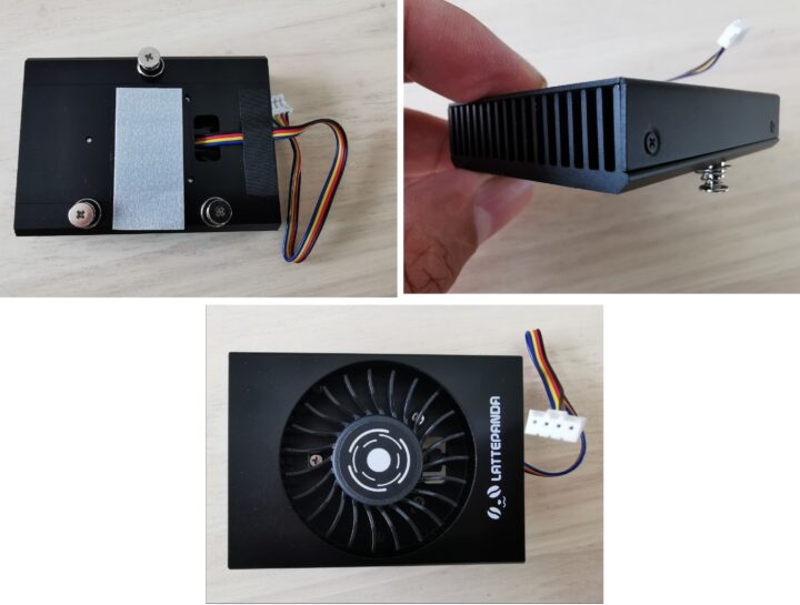
Waveshare 2-CH CAN MiniPCIe – An isolated CAN Bus mini PCIe card for Raspberry Pi CM4 and hosts with USB

Waveshare 2 CH CAN MiniPCIe Module

Waveshare 2-CH CAN MiniPCIe is a compact, CAN bus card featuring dual independent CAN channels with a wide baud rate range (10Kbps to 1Mbps). Unlike the esd electronics CAN-PCIeMiniHS/402, this Waveshare card is isolated, supports CAN2.0A/B protocols, and offers easy integration with laptops, industrial computers, and SBCs like Raspberry Pi via Mini PCIe or USB through an adapter. Additionally, the card supports Windows and Linux operating systems, making it ideal for applications like industrial automation and automotive diagnostics and development.

Previously we have covered many unique Waveshare products including the Waveshare 1.69-inch IPS touch LCD, ESP32-C6-Pico and ESP32-C6-Pico-M development boards, the Waveshare UGV Rover, and many others feel free to check those out if you are interested in different Waveshare products.

Waveshare 2-CH CAN MiniPCIe Module

Waveshare 2-CH CAN MiniPCIe CAN bus card specifications

  • CAN Bus
    • CAN channel – Dual-channel: CAN1 and CAN2 (independent and isolated)
    • Connector – CAN bus screw terminal (standard 1.25mm pitch)
    • Terminal resistor – Each CAN channel has a 120Ω terminal resistor
    • Baud Rate – 10Kbps~1Mbps (Configurable via software)
    • Protocol Support – CAN2.0A and CAN2.0B protocols, complies with ISO/DIS11898-1/2 standards
    • Hardware Support – High-speed CAN
    • Transfer speed – The receiving and sending of each CAN channel can reach: 8500 frames/s
    • Transmit buffer – 2000 frames receiving buffer and 1000 frames sending buffer per channel (automatically retransmit when transmission fails)
  • Mini PCIe Interface
    • Operating voltage – 3.3V
    • Communication method – USB 2.0 pins of the Mini PCIe interface
  • Indicators
    • PWR – Power indicator
    • SYS – System status indicator, normally off; keeps on when there is a bus error
    • CAN1 – CAN1 channel indicator (blinking when sending and receiving data)
    • CAN2 – CAN2 channel indicator (blinking when sending and receiving data)
  • Dimensions – 51×30 mm (mini PCIe module)
  • Operating Temperature – -40 to +85°C

2 CH CAN MiniPCIe details 19

The CAN protocol is fully compliant with the CAN2.0B specification, including backward compatibility with CAN2.0A, and complies with ISO11898-1/2 standards. Furthermore, it includes support for Windows XP/7/8/10/11 (32/64 bits) as well as various Linux distributions such as Raspberry Pi OS, Ubuntu (Jetson Nano), and VMware virtual PC environments.

2-CH CAN MiniPCIe M.2 Pin Description
Pinout diagram

for simplicity, the company also provides a pinout diagram of the mini PCIe interface for those who want to check things out in more detail.

2 CH CAN MiniPCIe details 7

The 2-CH CAN MiniPCIe adapter can directly be connected to the MiniPCIe slot of a CM4 baseboard or used with a laptop via a USB to MiniPCIe adapter board. Additionally, it connects to a Raspberry Pi using the same USB to MiniPCIe adapter, providing flexible solutions for a wide range of applications and ensuring robust CAN bus communication across different platforms.

2 CH CAN MiniPCIe details 25

The company provides examples for C++Builder, C#, VC, VB, VB.NET, Delphi, LabVIEW, LabWindows/CVI, Qt, and Matlab. Additionally, there are Python and Python-can samples, as well as Qt examples for Linux. This ensures that developers can easily work with CAN bus communication in their preferred development environments. more information about that can be found on the wiki page.

2 CH CAN MiniPCIe details size

The Waveshare 2-CH CAN MiniPCIe card can be purchased on AliExpress for $82.99 with free shipping at least to some countries and on Amazon for $89.99. It can also be found on the Waveshare store for $72.99 plus shipping.

The post Waveshare 2-CH CAN MiniPCIe – An isolated CAN Bus mini PCIe card for Raspberry Pi CM4 and hosts with USB appeared first on CNX Software - Embedded Systems News.
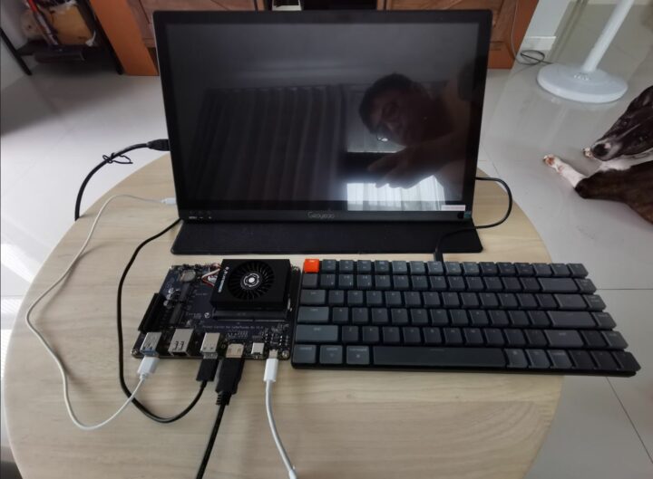
❌