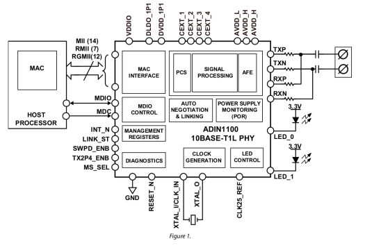
Microchip has released the LAN887x family of single-pair gigabit Ethernet transceivers adding to their line of Single Pair Ethernet (SPE) devices. This new family of transceivers supports 100BASE-T1(compliant with IEEE 802bw-2015) and 1000BASE-T1(compliant with IEEE 802.3bp) network speeds and can handle extended cable lengths up to 40 meters. They also integrate time-sensitive networking (TSN) protocols and comply with ISO 26262 functional safety standards. Additionally, they can operate in low-power mode with features like EtherGREEN technology and OPEN Alliance TC10 sleep mode. All these features make this IC useful for applications such as automotive, industrial, avionics, robotics, and automation fields.
Microchip previously released the LAN8770 100BASE-T1 Ethernet PHY Transceiver which has a max cable length of 15 meters for UTP (Unshielded Twisted Pair) cable and 40 meters for STP (Shielded Twisted Pair) cable. The speed was limited to 100 Mbps, but now, with the release of the new 1000BASE-T1 ethernet controllers, the data transmission speed has been significantly increased to 1 Gbps.
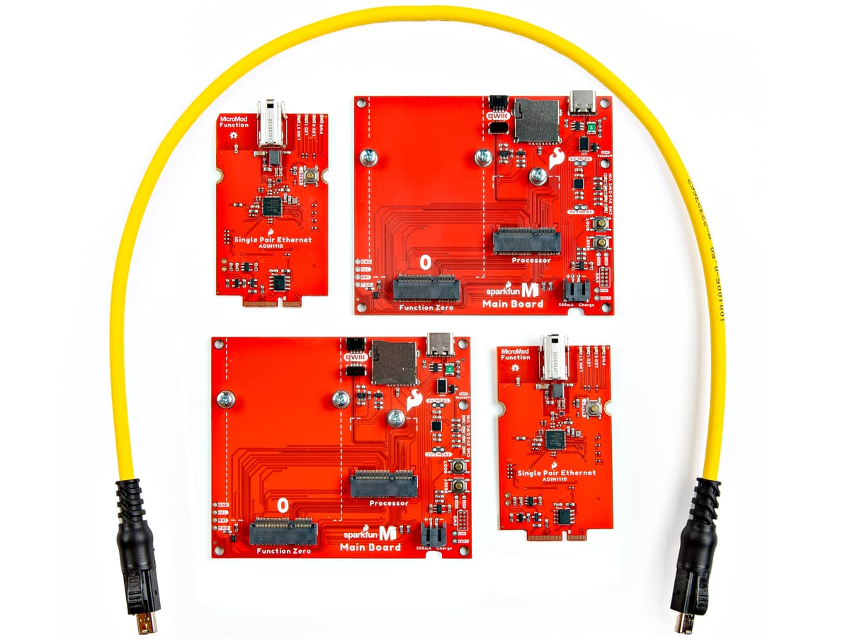
Device – LAN887x family of Ethernet PHY Transceiver
LAN8870 with RGMII and SGMII interfaces, extended cable reach for 1000BASE-T1 Type B (up to 40 meters)
LAN8871 with RGMII interface and similar features as LAN8870, but does not support the extended cable reach for Type B (See Cable reach section for details).
LAN8872 with SGMII interface and similar features as LAN8870, but does not support the extended cable reach for Type B.
Supported standards
IEEE 802.3bw-2015 (100BASE-T1)
IEEE 802.3bp-2016 (1000BASE-T1)
OPEN Alliance TC10 (ultra-low power sleep and wake-up)
IEEE 802.1AS-2020 (Time-Sensitive Networking)
IEEE 1588-2019 (Precision Time Protocol)
MAC interfaces – RGMII and SGMII
Cable reach
Type A – At least 15 meters
Type B (LAN8870B only) – At least 40 meters (potential for even longer reach)
Power management
FlexPWR technology for variable I/O and core power supply
EtherGREEN energy-efficient technology
Diagnostics
Cable defect detection
Receiver Signal Quality Indicator (SQI)
Over-temperature and under-voltage protection
status interrupt support
Loopback and test modes
Misc
Microchip Functional Safety Ready
MicroCHECK design review service available
Time-Sensitive Networking (TSN) ready
Temperature range
Automotive Grade 2: -40°C to +105°C
Industrial: -40°C to +85°C
Package – 48-pin VQFN (7 x 7 mm) with wettable flanks
The main differences between the three ICs are the MAC interface support and 1000BASE-T1 Type B capability. The LAN8870 supports both SGMII and RGMII, whereas the LAN8871 supports only RGMII, and the LAN8872 supports only SGMII. Only LAN8870 supports 1000BASE-T1 Type B with cable reach up to 40 meters. But the LAN8871 and LAN8872 do not support this feature. you can check out the datasheet for the LAN887x family for more information.
Extending single-pair Ethernet cables to 40 meters automatically introduces signal loss and timing issues to the network. The transmitted signal tends to weaken over longer distances which causes errors, especially in noisy environments. Additionally, maintaining proper impedance to avoid signal reflections becomes more difficult, which requires careful design and potentially increasing costs. So I would take the “with cable reaches beyond the IEEE 802.3bp standard of up to at least 15 meters for type A and up to at least 40 meters for type B.” with a grain of salt.
The company mentions that the chips are designed for low power consumption so they have introduced EtherGREEN technology and EN Alliance TC10 ultra-low-power sleep mode together the standby power of this chip goes as low as 16 µA. Additionally, this chip has support for RGMII and SGMII interfaces for design flexibility and simple integration with a wide range of MCUs and SoCs.
At the time of writing the company does not provide any pricing information for the new single-pair gigabit Ethernet transceivers, but you can find a little more information on the Microchips product page or the press release.
YouTuber “EDISON SCIENCE CORNER” has designed yet another Arduino UNO clone but with a twist as the board is made out of a flexible PCB.
Companies like JLCPCB, PCBWay, and others have been offering flexible PCB manufacturing services for a while, mostly for flat cables or small boards that need to fit around a case, but the Flexduino is a complete Arduino UNO clone made of a flex PCB, and it looks rather cool.
The flexible Arduino board does work as shown with the RGB LED and power LED in the photo above and YouTube video below, but its usefulness is rather limited, and some corners had to be cut as for instance there’s no ground plane.
Nevertheless, it’s a nice demo of flexible PCB technology. The video on the EDISON SCIENCE CORNER channel provides a short demo, shows how the PCB was designed (EasyEDA), and go through the ordering and assembly process. The project files for the Flexduino haven’t been shared as far as I can tell.
Renesas Electronics has introduced the RRH62000, a compact multi-sensor module for indoor air quality monitoring. It integrates particle detection, VOC, and gas sensing with an onboard Renesas MCU for sensor management. The module is designed for use in air purifiers, smoke detectors, HVAC systems, weather stations, and smart home devices.
The RRH62000 is an integrated sensor module that measures key air quality parameters, including particulate matter (PM1, PM2.5, PM10), total volatile organic compounds (TVOC), Indoor Air Quality Index (IAQ), estimated carbon dioxide (eCO2), temperature (T), and relative humidity (RH). These measurements are combined into a single package, with digital outputs available for each sensor, enabling simultaneous measurement. The module features a six-pin connector for easy plug-and-play integration.
The RRH62000 is available with the RRH62000-EVK evaluation kit, which simplifies the testing of the integrated sensor module. The module measures critical air quality parameters and connects to a Windows PC via USB. The evaluation kit includes a USB cable, ESCom board, RRH62000 sensor module, and a Quick Start Guide.
Renesas RRH62000 module specifications
MCU – Onboard Renesas microcontroller
Integrated multi-sensor module for air quality monitoring
Particulate matter (PM1, PM2.5, PM10)
Detects particle sizes from 0.3 µm to 10µm
Mass concentration measurement range: 0 to 1,000 µg/m³
Mass concentration resolution: 1 µg/m³
Number concentration range: 0 to 3,000 particles/cm³
Gas Sensor (ZMOD4410)
TVOC measurement range – 160 to 10,000 ppb
IAQ measurement range – 1 to 5 IAQ
Estimated CO2 (eCO2) range – 400 to 5,000 ppm
Humidity and Temperature Sensor (HS4003)
Humidity range: 0 to 100% RH
Humidity accuracy: ±5 to ±7% RH (20% to 80% RH range)
Temperature range: -40°C to 125°C
Temperature accuracy: ±0.4°C to ±0.55°C (-10°C to 80°C range)
Host interfaces – I2C and UART
Connector – ACES 51468-0064N-001 connector for data output and power
Power Supply
Input voltage: 4.5V to 5.5V
Current consumption during measurement – Max. 60mA
USB Type-C connector for connecting the communication board to the user’s computer
PMOD Connector (Female) for additional sensors via I2C interface
PMOD Connector (Male) for Renesas MCU EVKs
14-pin connector for connecting the environmental sensor boards to the ESCom communication board
Compatible Sensors
ZMOD4410 & RRH46410 for TVOC, IAQ
ZMOD4510 for O3, NO2, OAQ
ZMOD4450 for RAQ
HS3001 & HS4001 for RHT
FS3000 for Air velocity
RRH62000 for PM, TVOC, RHT
Misc
Power LED – Blue when power is ON
Status LED – Blue when ESCom is connected, blinks green when communication takes place
Power Supply
5V via USB-C connector for internal power
1.8V to 3.3V supply with external power supply pin
Dimensions – TBD
Jumper Settings and Connectors on the Environmental Sensor Communication Board
The RRH62000-EVK software, ES-Eval, provides a user-friendly graphical interface for configuring and evaluating the RRH62000 environmental sensor module. It features blocks for measurement control, sensor selection, algorithm configuration, signal analysis, and real-time data visualization, allowing users to easily manage and monitor the sensor’s performance. The software also automatically checks for and installs firmware updates for the ESCom communication board upon startup, ensuring optimal functionality. Users can download ES-Eval from the Software Downloads section on the Renesas website.
ES Eval software interface
The documentation for the kits includes a quick start manual, a list of components (BoM), circuit diagrams, and PCB design files for development and production purposes. all can be found on their respectiveproduct pages.
At the time of writing, I can see that all the major distributors have this board available on their websites including Mouser where the RRH62000 module is available for $38.08 and RRH62000-EVK is sold for $100.
MYIR has recently introduced MYC-LMA35 industrial SoM and its associated development board built around the Nuvoton NuMicro MA35D1 microprocessor with two Arm Cortex-A35 cores and one Arm Cortex-M4 real-time core for processing. The SoM comes in a BGA package with connectivity options such as dual Gigabit Ethernet, cellular connectivity, Wi-Fi/Bluetooth, and various other interfaces like RS232, RS485, USB, CAN, ADC, GPIO, and more. All these features make this SoM and its associated dev board useful for demanding edge IIoT applications like industrial automation, energy management systems, smart city infrastructure, and remote monitoring solutions.
M.2 socket and 2x SIM card slots for 4G/5G LTE module (USB-based)
USB
2x USB 2.0 host ports
1x USB 2.0 OTG port
Serial Interface
6x RS232 (isolated)
6x RS485 (isolated)
4x CAN Interfaces (w/ isolation)
Expansion
30-pin GPIO expansion header
2x Digital Input ports, 2x Digital Output ports
1x ADC Interface
Debug – 3x Debug Interfaces (one for Cortex-A35 core, one for Cortex-M4 core, one for SWD)
Misc – Reset, User, Power buttons
Dimensions – 150 x 110mm
Power
12V/2A DC (baseboard)
5V/1A DC (SoM)
Temperature Range – -40°C to 85°C
MYD-LMA35 Development Board Top and BottomMYC-LMA35 System-on-Module (Top view and Bottom view)
In terms of software, the company provides SDK featuring Linux 5.10, which includes u-boot, the kernel, and drivers in source code format which makes it easy to develop applications for the dev board. Moreover, the company also mentions there will be support for Debian and OpenWrt in the future. The documentation also includes pinout descriptions, certifications, and 3D STEP files of the MYC-LMA35 industrial SoM.
The Nuvoton NuMicro MA35D1 industrial SoM is available with either 256MB NAND flash for $39.80 or 8GB eMMC for $45.80. The MYD-LMA35 dev board goes for $99.00 with 256 MB NAND flash and $105 with 8GB eMMC flash. You can find more details and purchasing information on the product page.
After I reviewed the NapCat smart video doorbell last June, the company asked me to review a wireless NVR with solar-powered security cameras and I understood I would receive a kit with four solar-powered cameras and an NVR with storage preinstalled.
In this review, I’ll go through an unboxing, a quick teardown of the NVR, the installation process, and my experience with the Napcat NVR user interfaces (connected to HDMI) and the Napcat Life Android app which I also used with the video doorbell.
Napcat wireless NVR N1S22 kit unboxing
The package I’ve received reads “N1S22” model of a “Solar-powered Security Camera System” and is quite smaller than I expected.
One reason for the small size is that my kit only comes with two cameras instead of four, and the company also did a good job of making everything take as little space as possible. On the net, you’ll see it advertised as a “4K security camera system”, but the included 2.4 GHz WiFi cameras only have a resolution of just 2680×1620 (5MP).
The kit features a compact wireless NVR (center in the photo below), a 12V/2A power adapter for the NVR, an Ethernet cable, an HDMI cable, a USB mouse, two battery-powered security cameras, two small solar panels each with a 3-meter USB-C expansion cord and a solar mounting bracket, as well as a pack of screws, a reset needle pin, some stickers, and a quick start guide.
The NVR system features an HDMI port, an Ethernet RJ45 jack, a USB port for the mouse, a Reset pinhole, a USB port for storage, a microSD card slot (fitted with a 64GB microSD card), and a 12V DC jack.
The bottom side says the Napcat N1 is an 8-channel WiFi network video recorder.
The bottom cover is attached to the main unit through a magnet. You can press on the left or right side to take it out. From there you’ll find the QR code to add the NVR to the Napcat Life app, as well as a SATA tray secured by a screw and suitable for 2.5-inch SATA drives. I’ll just be using the provided microSD card for this review.
The front of the camera has some infrared LEDs, a spotlight (yellow), two indicator lights (red and green), a photosensitive sensor, a hole for a microphone, a PIR motion sensor, and a hole for the speakers on the bottom.
The bottom side of the “B220” camera has waterproof covers for a microSD card slot and a USB-C port for power. Since the videos will be recorded to the NVR, I did not add a microSD card to the cameras. I precharge the cameras with a USB power adapter before installation and connection to the solar panels.
Napcat N1 teardown
The NVR is easy to teardown, so I went ahead and we can see it’s based on a MediaTek MT7628DAN MIPS processor on a module attached to two interesting metal antennas… The main processor is under a heatsink, but it did come off easily, so I left that alone.
The bottom side features the SATA connector for a 2.5-inch hard drive.
Napcat wireless NVR setup
Before installing the cameras, we should make sure everything works first. So I connected the NVR to my router through Ethernet, added the mouse and an HDMI monitor, and connected the power supply.
We are asked to set up a password as the first configuration step. But this needs to be done with the mouse and a software keyboard that pops up. Not ideal. I tried to connect a USB keyboard to the storage port, but it did not work. I was too lazy to type a password with the software keyboard using the mouse, so I went to the Napcat Life mobile app for configuration. I first scanned the QR code under the device after tapping on “+ Add Device” in the app, and went through the configuration wizard.
After the NVR is properly detected, we’re asked to enter a device name, select the time zone, and we’re good to go… Just make sure to disable any VPN including Adblockers you may have when adding the device or it will fail (based on my experience with the video doorbell).
Now that the configuration is done, I went back to the display connected to the NVR and was just asked to input the password I had set in the mobile app.
Somehow, I had to confirm the time zone and date/time formats again…
… before selecting the storage device.
Finally, I was presented with the QR code, but I didn’t need it at this point, so I clicked on “Finish”.
Our two cameras can be seen in a 3×3 Mozaic for eight cameras, so everything is working, and it’s time to install the cameras in strategic locations.
There are various ways to install the cameras. I installed the first camera on the wall directly, and since I don’t have a ladder that would allow me to safely place the solar panel on the roof, I attached it to the cover of an old water pump in an area that gets sun a few hours a day. I did not use the solar panel bracket at all.
Camera 1 (CH1)
I install the second camera the same way but used the solar panel bracket to install the second solar panel in a location that gets sun a couple of hours a day.
Camera 2 (CH2)
At first, I felt the camera holder for the camera was insecure and a bird or strong winds could potentially bring it down, but then I noticed there was also a thread to insert a screw and keep it properly secured.
One other method is placing the camera directly into the solar panel bracket, but this would not have worked in my case due to the locations of the cameras not getting any sun at all. It’s also possible to mount it on the holding bracket provided with the kit, but that is probably not suitable for outdoor use since the holding bracket is simply placed on the surface and there aren’t any screws to secure it.
Napcat wireless NVR user interface
Once the installation is complete, we can go back to the NVR and check out the interface. Our two cameras are properly shown, but the live window shows paused videos because the cameras are only active when a person, vehicle, or motion is detected in order to save power and extend the battery life.
We can manually start each stream by clicking the blue play button with the mouse. We are asked to enter the NVR password each time we want to start using the device after a period of inactivity. I tried to disable it in the configuration menu but was unable to find a suitable option.
Nighttime capture also works well in black and white. The camera also has a color night vision option, but the spotlight is rather weak, so colors are not as good as a product like the Foscam SPC.
Color night vision screenshot from Napcat Life app
Besides the “Live” window, we can access other menus by clicking the Home icon on the top left corner of the display.
The Playback menu enables the other to check videos by day, watch them, and edit them as needed.
The Search menu is similar, but more useful, as it will show the more recent videos each with a thumbnail showing the person that was detected.
Clicking a video will enlarge the video and we can perform the same operations as in the Playback window…
… including zooming in on suspect individuals…
The Configuration section has various options for channel settings, display settings, encoding, privacy protection to define those where recording should be hidden, and camera maintenance.
The Events and Alarm option should that only pedestrian detection is enabled by default. Vehicle detection and motion detection are both turned off, but that’s fine in the current location of the cameras since car can’t access those locations or disabling motion detection extends the battery life.
I haven’t shown all configuration menus here, but everything is pretty standard. The NVR can be connected to WiFi instead of Ethernet if indeed, as in all battery-powered WiFi cameras I’ve tested so far ONVIF and RTSP are not supported since they are better suited to cameras operating 24/7.
I still did a quick test to see what would happen if I turned off my broadband router, meaning the NVR would exclusively operate in the LAN without access to the Internet. Everything worked like before. I could play the live videos, and human detection is working fine. Since it rained at the time, I also used an umbrella in a way that prevented the camera from seeing my face and upper body, but a pedestrian was still detected properly.
Napcat Life app
I connected the broadband router and went to the Napcat Life app. The settings are pretty common except for a few items.
I first went to the message notification section because I would not receive any notifications on my phone, but everything seems fine, and I’m unable to make that work. I can only manually check notifications when I get inside the app.
The Deterrence section also intrigued me… It’s used to enable the siren and strobe lights, but it did not work until I went to the Smart Event->Pedestrian & Vehicle Detection, and manually set Deterrence to ON there. The siren is quite loud, you can listen to it in the video below.
The rest of the app is pretty much standard and similar to the NVR interface with a Live and a Playback section…
You can select from some of the latest videos, or filter the videos for a given day.
Sadly, Download does not seem to work properly as it’s telling me the file will be downloaded to “Person Center->Albums”, but I’m unable to find any videos after download. It’s the exact same issue as in the Napcat smart video doorbell review two months ago… It’s disappointing.
Conclusion
The Napcat wireless NVR works reasonably well and is easy to install with solar-powered security cameras so no cabling is required through the house. Like most/all? recent security cameras, it supports AI features such as pedestrian and vehicle detection greatly reducing the number of false positives.
The camera outputs can be visualized through the NVR connected to an HDMI display and mouse, or through the Napcat Life mobile app for Android or iOS. The system works offline without access to the internet when visualizing the cameras from the NVR’s display.
Like other battery-powered WiFi cameras, I’ve tested the Napcat cameras do not support standard streaming protocols such as ONVIF or RTSP which means you are dependent on the company staying in business, at least when using the mobile app. I understand that ONVIF may not be suitable for battery-powered cameras, but I’ve tested cameras from five different vendors, and each requires its own app. I wish some standard like Matter could be more widespread. Another very disappointing issue is the download feature does not work from the mobile app, so it’s unclear how people can save important videos if needed.
I’d like to thank Napcap for sending the N1S22 wireless NVR kit for review. The kit can be purchased on Amazon for $299.99 after ticking on the $70 discount, and kits with four and six cameras go for $479.99 (with $100 discount) and $759.99 (no discount) on the same page.
The Netgotchi network security scanner is a simple, compact device based on an ESP8266 wireless microcontroller with a single goal: to defend your home network from intruders and potential bad actors. It is described as “Pwnagotchi’s older brother,” a network guardian that keeps your network safe instead of penetrating it.
If you are unfamiliar with Pwnagotchi, it is an A2C-based (advantage actor-critic) “AI” that can penetrate Wi-Fi networks using WPA key material obtained from passive sniffing or de-authentication attacks. The Netgotchi is a reverse Pwnagotchi that alerts you to intruders or breaches in your network. It runs on a simple microcontroller and cannot employ reinforcement learning like the Pwnagotchi. Rather, it pings the network periodically and reports any new potential security threats.
The device’s design is as simple as its purpose. It is an ESP8266 microcontroller connected to an OLED display and running an Arduino .ino script, enclosed in a 3D-printed case. It is powered via USB and does not contain batteries, so an external power bank is required for portable use.
Netgotchi wiring diagram
The Netgotchi software is open-source and available in ESP32 and ESP8266 versions in the GitHub repository, alongside an installation guide. The device has been tested and is compatible with Minigotchi firmware. Minigotchi is a currently archived project that is essentially a tiny Pwnagotchi, and performs deauth attacks and advertisements.
The Netgotchi scanner is limited to 2.4GHz Wi-Fi networks and will scan compatible networks at intervals. It scans hosts for vulnerable services such as Telnet, FTP, SSH, and HTTP and marks them as “WRNG!” to indicate a potential security risk. The “WRNG!” indicator can be toggled on or off using the securityScanActive flag. The Honeypot functionality exposes a service to lure potential intruders and triggers an alarm when breached. The scanner features a web interface and supports a headless mode for cyberdecks and other devices.
The Netgotchi network security scanner is priced at $69 on Tindie and comes pre-assembled with a USB cable in the box. Multiple color options are available on request. Due to the device’s open-source nature, there is no post-sale warranty.
There aren’t a lot of open-source devices aimed primarily at identifying security threats on your home network, but you may be interested in deauthentication hardware such as the Flipper Zero add-on, the Marauder Pocket Unit, and the Deauther Watch X.
ALLPCB is an ideal PCB manufacturer for PCB professionals and businesses thanks to additional customization options compared to competitors, monthly discounts for business users, and post-delivery payment options, besides ultra-fast delivery services and quality assurance services.
ALLPCB customization options
ALLPCB excels at higher specification boards and more complex PCB designs, which is why ALLPCB provides more customized quote options than competitors. Let’s take JLCPCB, one of ALLPCB’s main competitors, as an example starting with “Surface Finish” options for FR-4 material.
JLCPCB PCB specifications
JLCPCB offers three options, namely HASL (with lead), LeadFree HASL, and ENIG, but ALLPCB offers a total of 12 different surface finish options.
That would the the same first three as in JLCPCB, but also
ALLPCB also offers a PTH (Plating Through Hole) copper thickness option from
You can discover more customization options such as selecting our prepreg for various applications on ALLPCB’s online quote system.
A business-friendly PCB manufacturer
ALLPCB has a business verification program designed to enhance efficiency and reduce costs for business users. It offers business users monthly discounts and post-delivery payment options. After the verification, a business can have net 30-day payment terms to help with their cash flow. Also, they can enjoy ALLPCB prototyping services each month for a minimum cost of 1$.
ALLPCB’s PCB batch order prices are highly competitive. Aluminum PCBs start at $50 per square meter, and 6-layer PCBs start at $110 per square meter.
The company also recognizes the importance of time to market. ALLPCB offers significantly faster delivery times compared to industry standards. For example, 6-layer board batch orders (under 5 square meters) can be produced in just 3 days, while aluminum PCB batch orders (under 10 square meters) are produced in 2 days. This is 3-5 days faster than what competitors typically provide.
Quality assurance is equally important and all solder masks are even and thick, PCBs have smooth edges, and silkscreens are clear and accurate.
Give ALLPCB a try for just $1 with 1-6 layer PCB
If you think your business might benefit from ALLPCB PCB manufacturing services, you can have the opportunity to test the service for just $1 for an order of 5 pieces with up to 6 layers and a size of up to 150x100mm. You can check out the ordering process in our previous article about the promotion.
But this is about to change as an Espressif engineer nicknamed P-R-O-C-H-Y has recently added a Zigbee wrapper library for the ESP-Zigbee-SDK to Arduino Core for ESP32 that works with ESP32-C6 and ESP32-H2 as standalone nodes and other SoC can be used as radio co-processor attached to an RPC (802.15.4 radio layer).
The wrapper library currently supports the following:
Zigbee classes and all Zigbee roles
Zigbee network scanning
Allow multiple endpoints on the same Zigbee device (not tested yet)
Supported Home Assistant devices
On/off light + switch
Color Dimmable light + switch
Setting Manufacturer and model name
Other tasks currently planned include supporting “Temperature sensor + Thermostat” Home Assistant devices, updating ported examples to use the Zigbee library, and writing documentation… While the latter is still missing, you’ll find four basic Arduino code samples for the following Zigbee devices: a light bulb, a light switch, a temperature sensor, and a thermostat.
You can follow the progress of the port on GitHub or even contribute if you are interested in adding to the features. Over time this could potentially benefit open-source Arduino projects such as Tasmota which could add support for ESP32-C6 and ESP32-H2’s Zigbee connectivity on top of existing support for Zigbee MCUs from Texas Instruments (CC253X, CC26x2, CC13x2) and Silicon Labs (EFR32MG12/EFRMG21).
Waveshare has recently introduced the PCIe to MiniPCIe GbE USB3.2 HAT+ for Raspberry Pi 5 adding gigabit Ethernet, a mini PCIe socket for 4G LTE, and two USB 3.2 Gen1 ports to the popular Arm single board computer. The HAT+ is compatible with IM7600G-H-PCIE/EG25-G-mPCIe series 4G LTE modules with 4G/3G/2G global band and GNSS positioning. Additionally, it has a gigabit Ethernet with an onboard RJ45 port, two USB 3.2 Gen1 ports, an onboard power monitoring chip, and EEPROM. All these features make this HAT useful for applications such as industrial routers, home gateways, set-top boxes, industrial laptops, industrial PDAs, and much more.
2x USB 3.2 Gen1 ports driven by VL805 PCIe to USB 3.2 Gen1 HUB IC
USB Type-C interface for 4G networking, firmware updates, or external power supply
GPIO – Raspberry Pi GPIO header
Misc
Onboard power monitoring chip (INA219)
EEPROM
DIP switches for power control and USB signal direction
LED indicators for power and network status
Power Supply – 3V ~ 3.6V (5V through USB)
Dimensions – 65 x 56 mm
Operating Temperature – -40°C to +80°C
While it’s great to have a multi-interface HAT+ board, the PCIe interface of the Raspberry Pi 5 only supports up to PCIe Gen3 x1 with a maximum bandwidth of 8 Gbps. This HAT adds Gigabit Ethernet (1 Gbps), two USB 3.2 Gen 1 (2x 5 Gbps theoretical), and a 4G LTE module (variable bandwidth depending on network conditions) to the Raspberry Pi 5. So, there’s a good chance that the Pi’s PCIe bandwidth could become a bottleneck if you’re trying to max out the speeds of multiple interfaces simultaneously.
So, If you’re planning on using this HAT for demanding applications, then you should consider the Raspberry Pi 5’s PCIe bandwidth and plan accordingly.
PCIe TO MiniPCIe GbE USB3.2 HAT+ board details and pinout
As the device is plug-and-play the company mentions that the board supports Raspberry Pi OS, Ubuntu, OpenWrt, and other operating systems with reliable network speeds. Waveshare also provides installation instructions and demos on how to use the power monitoring IC with the Raspberry Pi 5.
PCIe to MiniPCIe GbE USB3.2 HAT+ Installation Instruction
The board has an operating temperature range of -40°C to +80°C and can be used for industrial applications such as rugged IPCs and digital signage, as well as routers, laptops, and tablets used in industrial settings. But bear in mind that Raspberry Pi Limited did not specify an operating temperature range for the Pi 5.
The PCIe TO MiniPCIe GbE USB3.2 HAT+ is available on Aliexpress for $29.46 and on Amazon for $37.43. If you need the 4G and GPS functionality, you can bundle the HAT with the SIM7600G-H 4G module and antennas, bringing the cost to $70.06 on Aliexpress and $95.99 on Amazon. You can also check out the Waveshare store for additional purchase options, but Waveshare’s pricing does not include shipping.
X96Q Pro+ is an Android 14 TV box powered by the new Allwinner H728 octa-core Cortex-A55 SoC with a Mali-G57-MC1 GPU, and a 4Kp60 / 8Kp24 H.265 and VP9 4Kp60 video decoder that looks very similar to the Allwinner T527 AIoT SoC.
The TV box ships with 4GB RAM and 32GB eMMC flash by default, and features an HDMI 2.0 port outputting up to 4K at 60 Hz, a 3.5mm audio jack, an optical S/PDIF output, a gigabit Ethernet port, WiFi 6 and Bluetooth 5.0 connectivity, and a few USB ports.
X96Q Pro+ specifications:
SoC – Allwinner H728
CPU – Octa-core Arm Cortex-A55 processor in two clusters of four cores four cores
Package – FCCSP 660 balls
17 mm x 17 mm size, 0.5 mm ball pitch, 0.3 mm ball size
Manufacturing process – 22nm ULP
System Memory – 4GB (2GB optional)
Storage
32GB eMMC flash (16/64GB optional)
MicroSD card slot
Video Output – HDMI 2.0a up to 4Kp60 with 10-bit HDR support
Audio – 3.5mm audio jack, optical S/PDIF, digital audio via HDMI
Networking
Gigabit Ethernet port
Dual-band WiFi 6 and Bluetooth 5.0
USB – 1x USB 3.0 port, 2x USB 2.0 ports
Misc
Power button
Update pinhole
Front panel display
Optional RTC
Power Supply – 5V/3A via DC jack
Dimensions – 140 x 90 x 20mm
Weight – 150 grams
The TV box ships with a remote control, a power adapter, an HDMI cable, and a user manual. The main benefit of the X96Q Pro+ is that it runs the most recent Android 14 (for TV?) operating system. The Allwinner H728 “Decoding Platform Processor” does have some interesting interfaces like PCIe 2.1 x1, 30x PWM, two gigabit Ethernet MAC, and more that make it look like the Allwinner T527 even more, so it’s probably just handled by a different business unit within Allwinner, and that’s potentially the same silicon.
DeepComputing DC-ROMA RISC-V Pad II is a 10.1-inch tablet based on the same SpacemIT K1 octa-core 64-bit RISC-V processor found in the DC-ROMA RISC-V Laptop II introduced a few months ago, as well as in the MILK-V Jupiter mini-ITX motherboard.
The RISC-V tablet features up to 16GB LPDDR4, 128GB eMMC flash, a 10.1-inch capacitive touchscreen display with 1920×1200 resolution, a 5MP rear camera, a 2MP webcam, a USB-C port for peripherals and/or an external display, and a 6,000 mAh battery.
Networking – Not specified, but potentially Wi-Fi 6 & Bluetooth 5.2 like in the laptop
USB – 1x USB 3.2 Gen 1 Type-C port with DisplayPort Alt mode
Battery – 3.5V/6,000 mAh (max) cobalt battery
Power Supply – Via USB-C port (TBC)
Dimensions and Weight – TBD
The tablet runs Ubuntu 24.04 right now, but DeepComputing says models with 16GB RAM will be upgradeable to Android 15 AOSP in Q4 2024… Please note that while Linux RISC-V support has made great progress, our review of the Jupiter RISC-V motherboard based on the same SpacemIT M1/K1 revealed more work is needed. I still think the Android 15 release schedule is probably way too optimistic since Android 15 AOSP is yet to be released…
If you are a developer interested in checking out the RISC-V tablet, you can pre-order it with a 20% deposit for as low as $149 in the 4GB/64GB configuration. The top model with 16GB RAM and a 128GB eMMC flash goes for $299. A few more details may be found in the press release, and the tablet is currently showcased at the RISC-V Summit China 2024 in Hangzhou until August 25.
DeskPi RackMate T1 is a U8 desktop rack especially suited to SBC users with support for Raspberry Pi SBCs, NVIDIA Jetson developer kits, Raxa ROCK 5B pico-ITX SBC, mini-ITX motherboards, and more.
The RackMate T1 chassis is made of aluminum alloy and acrylic frame and its 8U form factor (406 (H) x 280 (L) x 200 (W) mm) allows it to be placed either on a desk or a floor of a home lab.
DeskPi RackMat T1 highlights:
Mounting holes on all trays
Raspberry Pi 3B, 3B, +4B, and DeskPi aux board bring HDMI and USB-C to the front (M2.5 screws) – star holes
Radxa ROCK 5B pico-ITX SBC (M3 screws) – round holes
2.5-inch drives
Screw kits with M2.5 screws and standoffs, M3 screws, and a screwdriver
Dimensions – 406 x 280 x 200 mm (H x L x W)
Materials – Aluminum alloy and acrylic frame
The documentation is extremely poor with low-resolution images and confusion with “optional accessories” that are shown in all photos as if they were included:
Rack shell
Blank panel
SBC shell
Mini-ITX shell
10-inch network switch
For example, I can see at least three blank panels, one rack shell, and one SBC shell in the kit below. One would assume those are included, but it’s hard to tell since the company does not make it specific.
It’s not the first time we have written about rack solutions for Raspberry Pi and other SBCs, and we previously covered a 19-inch rackmount from MyElectronics taking up to 16 Raspberry Pi boards, which may be more cost-effective for European users although you’d need to bring your own rack/chassis.
The DeskPi RackMate T1, also called the “GeeekPi 8U Server Cabinet” can be purchased for $179.99 on Amazon and most users seem happy about it, except one that received a kit with a cracked top acrylic panel. The accessories mentioned above sell for $12 to $36 on Amazon. TheRackMate T1 can also be purchased on the company’s store, but they don’t recommend it due to hefty shipping charges from China…
Hardkernel has just launched the ODROID-M2 low-profile SBC based on a Rockchip RK3588S2 octa-core Cortex-A76/A55 AI SoC with up to 16GB LPDDR5, 64GB eMMC flash, an M.2 PCIe socket, support for three displays through HDMI, USB-C, and MIPI DSI interfaces, gigabit Ethernet, and more.
CPU – Octa-core processor with 4x Cortex-A76 cores @ up to 2.3 GHz (+/- 0.1Ghz), 4x Cortex-A55 cores @ up to 1.8 GHz
GPU – Arm Mali-G610 MP4 GPU @ 1 GHz compatible with OpenGL ES 3.2, OpenCL 2.2, and Vulkan 1.2 APIs
VPU – 8Kp60 video decoder for H.265/AVS2/VP9/H.264/AV1 codecs, 8Kp30 H.265/H.264 video encoder
AI accelerator – 6 TOPS (INT8) NPU
System Memory – 8GB or 16GB 64-bit LPDDR5 (4GB RAM variant coming soon).
Storage
64GB eMMC flash
MicroSD card slot with UHS-I SDR104 mode support
M.2 M-Key socket with PCIe 2.1 x1 for NVMe SSDs
Video output
HDMI 2.0 up to 4K @ 60Hz with HDR, EDID
DisplayPort via USB-C port
30-pin MIPI DSI connector (note: different from the 31-pin connector on the ODROID-M1)
Networking – Gigabit Ethernet RJ45 port
USB
USB 2.0 host port
USB 3.0 host port
USB 3.0 Type-C port with DP Alt-Mode (not a power source/sink)
Expansion
40-pin Raspberry Pi-compatible GPIO header
14-pin GPIO header
Debugging – Serial debug console
Misc
Power button, Reset button
System LEDs
Red (POWER) – Solid light when DC power is connected
Blue (ALIVE) – Flashing like a heartbeat while the Linux kernel is running, solid light in u-boot.
PCF8536 RTC with CR2032 backup battery holder
Boot priority switch for eMMC or microSD card
Power Supply – 7.5V to 15.5V DC input via 5.5/2.1mm power barrel jack; 12V/2A power adapter recommended
Power Consumption (Hardkernel numbers)
Power Off – About 0 Watt
IDLE – About 1Watt without any peripherals
CPU stress test – About 7.5 Watts (Performance governor) without any peripherals
Dimensions – 90 x 90 x 21mm
Weight – 78g including heatsink, 58g without heatsink
ODROID-M2 fitted with M.2 SSD
ODROID-M2 block diagram
You may have heard about the RK3588S, but not necessarily about the RK3588S2, and we wondered about the difference between the two in our Radxa ROCK 5C article:
how does RK3588S2 differ from RK3588S? They are basically the same except the RK3588S2 comes with an additional MIPI CSI interface which is not used in the ROCK 5C.
The MIPI CSI interface is not used in the ODROID-M2 either, but there must be a good reason why both companies selected the RK3588S2 instead, either pricing or availability…
In terms of performance, Hardkernel explains the ODROID-M2 is better than the ODROID-M1S in every way:
Multicore performance is about 3 times faster.
About twice the memory bandwidth with LPDDR5 64-bit RAM
The Mali-610 GPU is over 5 times faster.
The 6TOPS NPU is over 3 times faster.
The 64GB eMMC flash is twice as fast thanks to an HS400 interface.
ODROID-M1 vs ODROID-N2+ vs ODROID-M2 benchmark comparison
One downside is that the new ODROID-M2 is fitted with a heatsink with a fan for cooling, while the earlier models could operate fanlessly. Having said that, Hardkernel mentions the fan seldom rotates in the video below, so I’d assume some people may just decide to disconnect the fan.
Hardkernel is usually better than most other SBC vendors when it comes to software support. We typically just get a list of operating systems, but the Korean company goes into more detail when it comes to software features.
Android 13
Based on AOSP
Customized raw GPIO access framework (in other words, GPIOs works in Android).
SPI ( CAN receiver, LED strip lights, IO expander)
Ubuntu 24.04 with a newer kernel version will be released in a few months
You can see a short demo in Android 13 with two 4K displays one playing a 4K video and the other running 3DMark with 3D graphics acceleration. More details about the hardware and software can be found on the wiki.
Hardkernel sells the ODROID-M2 SBC on its own store for $115 with 8GB LPDDR5, 64GB eMMC flash, and an enclosure, while the 16GB RAM model goes for $145. The upcoming 4GB RAM model will sell for under $100, more exactly for $95 once it becomes available.
Mekotronics R58-4×4 3S is another Rockchip RK3588-based Arm PC and digital signage player from the company with unusual features such as a 3-inch display on the front panel as well as four HDMI inputs supporting up to 4Kp60 sources.
The embedded PC features up to 16GB RAM and 128GB eMMC flash, an M.2 PCIe socket for NVMe storage, an 8Kp60-capable HDMI 2.1 video output port, gigabit Ethernet and WiFi 6 connectivity, a mini PCIe socket and NanoSIM card slot for a 4G LTE/GPS module, and more.
M.2 M-Key (PCIe 3.0) socket for an M.2 2280 NVMe SSD
MicroSD card slot
Video Output
HDMI 2.1 port up to 8Kp60
Internal LVDS connector
Video Input – 4x HDMI inputs up to 4Kp60
Display – 3-inch display connected over MIPI DSI
Audio – 3.5mm jacks “audio”, Line-in, and Line-out
Networking
Gigabit Ethernet RJ45 jack
WiFi 6
Optional 4G LTE/GPS module via mini PCIe socket and nano SIM card slot
Up to two external antennas
USB – 2x USB 3.0, 2x USB 2.0, 1x USB Type-C port
Expansion
Internal GPIO header
M.2 socket for storage
Mini PCIe socket + NanoSIM card slot for cellular connectivity
Misc
Power button
Front panel buttons (D-Pad, 3x user buttons)
RTC clock
Power Supply – 12V/3A via 5.5×2.1mm DC jack
Dimensions – TBD (Aluminum enclosure)
Two HDMI inputs can be found on the left side and two HDMI inputs on the right side.
The company provides support for Android 12, Debian, and Armbian (Ubuntu) operating systems as well as Buildroot built system. We don’t have that many extra details at this time, but the company showcases the Arm PC with Android 12 in the video below showing the 3-inch display mirroring the HDMI output, and also demonstrating the HDMI input feature.
We were not given pricing information for this specific model. More details may be found on the product page.
MeatPi Electronics introduced the WiCAN Pro, an ESP32-S3-based OBD scanner, and the successor to WiCAN-OBD. Equipped with an OBD-II interface IC, it provides full support for all legislated OBD-II protocols. It offers compatibility with multiple CAN Bus protocols, including three standard CAN Bus and single-wire CAN Bus.
The previous generation WiCAN module came in an OBD or USB-based version. The WiCAN Pro only has an OBD interface, but another significant difference from the previous product is that it features a USB host port. This port can power USB devices up to 1.5 amps at 5 volts and enables capabilities like adding GPS or cellular-based radios, like with meatPi’s ESPNetLink add-on.
The WiCAN Pro plugs into the vehicle’s OBD port and is powered by the vehicle’s battery. The voltage range is 6.5V to 18V, consuming about 35mA during operation and 2.8mA in sleep mode.
ESP32-S3-based OBD scanner WiCAN Pro PCB
The device includes dual UARTs, one dedicated to flashing and debugging the ESP32-S3 and the other configurable for sending commands to the OBD chip, providing flexibility for developers working on custom automotive applications. According to the product page, WiCAN Pro can be integrated with Home Assistant and other IoT applications without requiring external apps. This feature enables users to incorporate vehicle data into a smart home ecosystem, allowing for automated vehicle diagnostics and monitoring.
Graphical Diagram of WiCan Pro
The ESP32-S3-based OBD scanner WiCAN Pro runs on the versatile WiCAN firmware, which is already available and runs on an ESP32. This firmware can send MQTT messages about the vehicle’s health, integrate with Home Assistant, or drive a RealDash display with real-time information. Moreover, this open-source device is compatible with a range of established OBD diagnostic apps including Car Scanner, Torque Lite or Pro, OBD Auto Doctor, BimmerCode, and OBD Fusion.
RealDash dashboard example. More designs can be found in the RealDash gallery
The company also offers a feature comparison between the WiCAN Pro, WiCAN, and the OBDLink MX+.
The WiCAN Pro campaign launched on Crowd Supply and has raised $6,000 so far with 35 days remaining. The product is priced at $80, with an additional $8 for U.S. shipping and $18 for international shipping. Deliveries are expected to start by mid-February 2025.
There are a few boards that integrate an HDMI port such as the Olimex RP2040-PICO-PC, Solder Party RP2xxx Stamp Carrier XL, or Adafruit Feather RP2040 among others, but most boards don’t include an HDMI port. What they do typically have are GPIO headers, and an HDMI to screw terminal adapter would allow users to easily add an HDMI port to their existing board without soldering simply by using jumper wires, or with a bit more work an old HDMI cable.
All HDMI to screw terminal adapters are pretty basic with an HDMI male connector compatible with HDMI 2.0 (24AWG) and two terminal blocks with 10 poles each all housed in a plastic enclosure. No soldering is required unless your module/board does not come with headers with only through or castellated holes.
While there are 20 pins in total wiring to a Raspberry Pi RP2040 should only require about 11 pins based on the schematics for the PicoDVI project.
Solder Party’s RP2350 Stamp is an update to the company’s tiny RP2040 Stamp module based on a Raspberry Pi RP2350A, and they also introduced the RP2350 Stamp XL module that makes use of the extra GPIO pins on the RP2350B, and a “RP2xxx Stamp Carrier XL” carrier board taking either module.
RP2350 Stamp and RP2350 Stamp XL
The RP2350 Stamp has exactly the same layout as the RP2040 Stamp and mostly benefits from the more powerful Cortex-M33 cores, additional memory, and security features, while the XL variant adds more GPIOs, footprint for a PSRAM chip, as well as UART and SWD connectors. Both come with a 16MB SPI flash for storage.
LiPo supply and charging circuit (with charging LED)
Dimensions – 44.5 x 25.4 mm
RP2350 Stamp XL pinout diagram
The RP2350 Stamp XL module looks like a nice platform to fully experiment with the new Raspberry Pi RP2350B microcontroller, especially when used with the carrier board detailed below.
RP2xxx Stamp Carrier XL
The RP2xxx Stamp Carrier XL follows the Arduino Mega/Due form factor enabling mechanical and electrical compatibility with many existing shields including ones made for the Arduino UNO.
Specifications:
Compatible with RP2350 Stamp modules described above
Storage – MicroSD card socket
Video Output – Micro HDMI port connected to the HSTX peripheral
USB – USB Host and Device connector with a toggle switch
Expansion
Arduino-compatible headers; note: 3.3V IOs, the pins are not 5V-tolerant.
Qwicc connector for I2C modules
PMOD header
Debugging- SWD and UART connectors for the Raspberry Pi Pico Probe
Misc
2x user buttons, Boot and Reset buttons
USR LED
Power LED (3.3V)
Power Supply
7V to 12V DC jack; center positive
3.7/4.2V LiPo connector
5V via USB port
Dimensions – 101.6 x 53.34 mm
One neat feature is the 3-in-1 SMD/TH/FlexyPin Stamp footprint allows for three different assembly options: direct soldering, and female headers or flexypins during development/prototyping, or when used as a flashing jig for the RP2350 Stamp modules.
Flexypins (top), soldered (bottom left), and headers (bottom right)
The modules ship with CircuitPython firmware that includes a board file for the Carrier which you can access by using the following line in your code:
Sadly the Raspberry Pi RP2350A/RP2350B modules and carrier board are not available right now, but should be in the next few weeks. We already have pricing information with the RP2350 Stamp and RP2350 Stamp XL to sell for the same $11 and the carrier board for $75.0. Interested customers can already join the waitlist at Solder Party’s Lectronz Store.
The Vecow TGS-1000 Series is an ultra-compact, fanless, stackable embedded computer that includes the TGS-1000 and TGS-1500 models, powered by the latest Intel Core Ultra Metero Lake processors with integrated CPU, GPU, and NPU. It supports up to 96GB DDR5 memory and stackable expansion options for networking, serial, wireless, and more. This series is optimized for edge AI applications, offering up to 14% increased CPU productivity and enhanced graphics capabilities.
The TGS-1000 Series offers up to five independent displays through two HDMI and three DP ports. It features a variety of I/O connections, including up to 5 USB 3.0 ports (4x Type-A and 1x Type-C) and one 2.5GbE LAN supporting TSN, making it ideal for vision and automation applications. Its modular design allows flexible expansion for USB, isolated DIO, COM, LAN, or 4G/LTE, suitable for AI, smart retail, office communication, and gaming. The TG-1500 series adds support for MXM graphics cards.
Previously, we wrote about the stackable Intel Atom-based industrial mini PC ADLEPC-1520 and the Intel Celeron-based Acer Revo Build mini PC. We’ve also covered other Intel Core Ultra processor-based mini PCs and SBCs, like the DFI X6-MTH-ORN, UP Xtreme i14, AAEON PICO-MTU4, and Vecow SPC-9000. Feel free to check these out if you’re interested in similar products.
Vecow TGS-1000 series specification
SoC
Intel Core Ultra 7 165H 16-core (6P+8E+2LPE) processor @ 1.4 / 5.0 GHz with 24MB cache, Intel AI Boost NPU
Intel Core Ultra 5 135H 14-core (4P+8E+2LPE) processor @ 1.7 / 4.6 GHz with 18MB cache, Intel AI Boost NPU
NVIDIA Ada Lovelace/Ampere/Turing supports max 9728 NVIDIA CUDA cores, 384 Tensor Cores, or 76 RT Cores, delivering max 41.15 TFLOPS peak FP32 performance. Suitable for high-performance computing, gaming, and professional applications.
Intel Xe HPG microarchitecture is a High-Performance graphics designed to deliver up to 72 TOPS for AI processing.
System Memory – 2 x DDR5 5600MHz SO-DIMM, up to 96GB
Storage
1x M.2 Key M Socket (2280, PCIe 4.0 x4)
1x M.2 Key M Socket (2242, PCIe 4.0 x4)
Video Output
2x HDMI 2.1 ports up to 4096 x 2304 @ 60Hz
1x DisplayPort (DP) 1.4 up to 3840 x 2160 @ 60Hz by USB Type-C
TGS-1500 additional ports – 2x Display Port (DP) 1.4 up to 4096 x 2304 @60Hz by MXM
Audio – Realtek ALC888S-VD, 7.1 Channel HD Audio with 1 Mic-in and 1 Line-out
Networking – Intel I226 2.5GbE LAN with TSN support
USB
2x USB 3.2 Gen 2 Type A
1x USB 3.2 Gen 2×2 Type C (5V/3A)
2x USB 2 Type A
Expansion
1x M.2 Key E Socket (2230, PCIe x1/USB)
2x expansion connector for docking module
Optional stackable docking modules
TGS-101 – 16-bit GPIO
TGS-102 – 16-bit Isolated DIO (8 DI, 8 DO)
TGS-103 – Type-A MXM GPU (without MXM GPU)
TGS-104 – 2 Isolated COM (RS-232/422/485)
TGS-105 – Dual USB 3.0
TGS-106 – Dual 1GbE LAN
TGS-107 – 4G LTE module with SIM socket
Accessories module
WiFi & Bluetooth module with antenna
Mini PCIe 4G/GPS module with antenna
M.2 Key-M storage module
Misc
Power, HDD LEDs
Watchdog Timer – Reset 1 to 255 sec./min. per step
Smart Management – Intel vPro, TCC, TSN, PXE, Wake on LAN
HW Monitor – Monitoring temperatures and voltages. Auto throttling control when CPU overheats.
Power Supply
TGS-1000 – DC 12V to 24V with V+, V-, Frame Ground
TGS-1500 – DC 24V Only with V+, V-, Frame Ground
Dimensions & Weight
TGS-1000 – 117 x 120 x 38mm | 900 grams
TGS-1500 – 117 x 120 x 88.3mm | 1.4 kg
Temperature Range
Operating
TGS-1000 : 0°C to 55°C
TGS-1500 : 0°C to 45°C
Storage – -40°C to 85°C
Humidity – 5% to 95% Humidity, non-condensing
Shock – IEC 61373: 2010
Vibration – Rolling Stock Equipment, Shock and Vibration Tests
EMC – CE, FCC, ICES, EN50155, EN50121-3-2
TGS-1000 (left) and TGS-1500(right)
The system can be wall-mounted with a bracket, and Vecow also offers VESA or DIN Rail mounts as options. The company supports Windows 11/10 and Linux on the fanless TGS-1000 Series embedded system. Vecow also mentions VHub AI Developer, VHub ROS, and VHub EtherCAT as optional software, with OpenVINO toolkits supporting 500+ AI models optimized for AI computing.
TGS-1000 (left) and TGS-1500(right)
Vecow stackable embedded computer is available in four variants: TGS-1000-165H/135H and TGS-1500-165H/135H. The company hasn’t provided availability or pricing details, but this type of system is expected to cost a thousand dollars and up. More information about the TGS-1000 and TGS-1500 can be found on the product page.
DFI RPP051 is a 2.5-inch Pico-ITX SBC built around 13th Gen Intel Core processors ranging from the dual-core Intel Processor U300E to the 10-core Intel Core i7-1365UE. It supports up to 32GB DDR5 SO-DIMM memory and accommodates M.2 NVMe and SATA storage devices. Connectivity options include a 2.5GbE LAN port, DP++ and eDP display interfaces, USB 3.2 Gen 2 and USB 2.0 ports, RS-232/422/485 interfaces, along with I2C and GPIO for expansion.
The DFI RPP051 first came to our attention while covering the AAEON PICO-RAP4 which is also an SBC with a Pico-ITX form factor, we have also written about many x86 and Arm Pico-ITX boards including AAEON PICO-MTU4, the AAEON RICO-3568, the GIGAIPC PICO-N97A and many other feel free to check them out if you are looking for compact and powerful SBCs.
The company mentions that the board supports Windows 10, Windows 11, and Linux but while searching on the official download center I couldn’t find drivers for Linux. You can also find datasheets, User’s Manual, and a list of certifications on the same page.
The DFI RPP051 Pico-ITX SBC comes in seven different versions for various industrial and non-industrial uses and Currently, DFI has only released pricing for three models with 13th Gen Raptor Lake processors: the Core i3-1315UE model at $620, the mid-range Core i5-1345UE model at $891, and the high-end Core i7-1365UE model at $1,128. You can check out pricing and other details on their e-store page.
The new Raspberry Pi RP2350 USB-C board has the same form factor but adds eight more GPIOs on the bottom with pads for a total of 19 GPIOs, and we lose two LEDs for serial port connectivity. Most people will still be fine with the XIAO RP2040, but if you need a more powerful microcontroller, extra memory, a few extra GPIOs, and built-in security, then the XIAO RP2350 will be an improvement.
CPU – Dual-core Arm Cortex-M33 processor @ 150MHz (Note: again RISC-V is not mentioned at all by Seeed Studio, like for the Cytron MOTION 2350 Pro board)
Memory – 520KB internal RAM
8KB OTP Storage
Storage – 2MB flash (Seeed Studio writes PSRAM, but that seems odd unless there’s non-volatile PSRAM…)
USB – 1x USB type C port for power and programming
Expansion I/Os
2x 7-pin 2.54mm pitch headers and castellated holes with up to 3x analog inputs, 11x GPIO/PWM, 1x SPI, 1x UART, 1x I2C, 5V, 3.3V, and GND;
8x solder pads with up to 8x GPIO/PWM, 1x SPI, 1x UART, 1x I2C
3.3V I/O voltage (not 5V tolerant)
Security – OTP, Secure Boot, Arm TrustZone
Debugging – SWD pads
Misc
User LED, power LED, 2x LEDs for serial port downloading
Reset Button/ Boot Button
RGB LED
Power Supply
5V via USB-C port
Battery pads (BAT +/-)
Dimensions – 21 x 17.5 mm
Pinout diagram (top)Pinout diagram (bottom)
Software-wise, Seeed Studio provides support for MicroPython and C/C++ only, and the XIAO RP2350 does not support Arduino although I understand it’s only a question of time until Arduino Core for RP2350 is implemented. You’ll find getting started instructions for MicroPython and C on the documentation website.
The XIAO RP2350 benefits from the ecosystem of other XIAO boards with carrier boards, Grove sensors, actuators, displays, LED matrices, and more.
Add-on for XIAO boards
Seeed Studio sells the XIAO RP2350 on its online store for $5.00, or even cheaper the XIAO RP2040 currently sold for $5.40. Maybe that’s an introduction price, and note the company only takes single unit orders at this stage as only 400 pieces have been manufactured in the first run.
As mentioned in the Raspberry Pi Pico 2 article, third-party RP2350 boards are already available, and one of them is the MOTION 2350 Pro board from Cytron designed for robotics and motor control. The board features a DC motor driver capable of controlling up to 4 brushed DC motors with voltage ratings from 3.6V to 16V.
It also features eight 5V servo ports, eight GPIO ports, and three Maker ports for sensor or actuator modules. Each I/O is matched with its own LED which makes the board ideal for the education market and also simplifies debugging. Finally, a USB 1.1 host port is present to connect peripherals such as the RF dongle for a joystick or a keyboard.
CPU – Dual-core Arm Cortex-M33 processor @ 150MHz (RISC-V cores are not mentioned, so they are likely not used at all)
Memory – 520KB internal RAM
8KB OTP Storage
Robot control
4x DC motor drivers with quick test buttons
8x servo motor ports (3x 8-pin headers)
Maximum DC Motor current
Continuous: 3A
Peak: 5A
USB – 1x USB 1.1 Type-A host port
Expansion
3x Maker ports
8x 3.3V GPIO breakout (3x 8-pin headers)
Misc
24x Status indicator LEDs
8x for servo ports
8x for 3.3V GPIO breakout
8x for DC motor drivers
2x RGB LED (Neopixel Compatible)
12x Push Button
8x quick test buttons for DC motors
2x user buttons
BOOT button
RST button
Piezo Buzzer with mute switch
On/Off Switch with MOSFET Shock-Proof Circuit
Input Power
5V via USB-C port
3.6V to 16V via VIN pin
Dimensions – 95.2 x 57.2 mm
The RP2350 microcontroller can be found on the bottom side, and as usual, there’s a white area to write the student’s name
The MOTION 2350 Pro board comes preloaded with CircuitPython by default but also supports MicroPython, and Arduino support is coming soon. Accessories in the package include a 4-pin STEMMA QT/Qwiic JST-SH cable with female sockets (150mm), two Grove to JST-SH cable (200mm), a set of silicone bumper, four “building block friction pins” that look compatible with LEGO ecosystem, and a mini screwdriver.
It’s ideal to build robots such as the mecanum wheel robot shown below, or various multi-servo projects.
You can test the board as soon as you receive it with a default CircuitPython program preloaded on the MOTION 2350 Pro board. Simply connect it to the USB power source, and you’ll be greeted by a melody tune and blinking LEDs. You can also press the GP20 and GP21 push buttons to run another demo code. See what it looks like in the video embedded below.
If I connect the board to my PC, a new “CIRCUITPY” drive will show up with CicuitPython code, libraries, and some other files:
You can look through the code and modify it as needed by opening code.py in a text editor or an IDE such as Thonny.
Cytron sells the MOTION 2350 Pro for $19.92 on its online shop. Note that’s the launch price, and the regular price is $24.90. A mobile robot kit is also in the works, but not for sale right now.
The Raspberry Pi Pico 2 is an MCU development board based on the new Raspberry Pi RP2350 dual-core RISC-V or dual-core Cortex-M33 microcontroller with 520 KB on-chip SRAM, a 4MB flash, a micro USB port for power and programming and the same GPIO headers as the Raspberry Pi Pico board with an RP2040 dual-core Cortex-M0+ microcontroller with 264KB SRAM.
The RP2350 embeds both an open-source Hazard3 RISC-V dual-core CPU and a dual-core Cortex-M33, but only one cluster can be used at a given time. Apart from the faster MCU cores and higher SRAM capacity, the RP2350 is about the same as the RP2040, albeit it also adds one extra PIO block bringing the total to three. One important new feature is built-in security when using Arm Cortex-M33 cores with Trustzone and other security features.
Raspberry Pi RP2350 microcontroller
Let’s have a closer look at the RP2350 microcontroller, before checking out the Raspberry Pi Pico 2 board.
Raspberry Pi RP2350 block diagram
Raspberry Pi RP2350 specifications:
CPU
Dual-core Arm Cortex-M33 @ 150 MHz with Arm Trustzone, Secure boot OR
HSTX (high-speed serial transmit) streams data from the system clock domain to up to 8 GPIOs (IO12-IO19) at a rate independent of the system clock.
Temperature sensor
Security
8KB of anti-fuse OTP for key storage
SHA-256 acceleration
Hardware TRNG
Fast glitch detectors
Debugging – SWD Debug interface
Low power – Extended low-power sleep states with optional SRAM retention: as low as 10 μA DVDD
Package
RP2350A – QFN-60; 7×7 mm
RP2350B – QFN-80; 10×10 mm
Raspberry Pi RP2350A package used in Raspberry Pi Pico 2Raspberry Pi RP2350B package
As I understand it, the RP2350A package offers also the same pinout as the RP2040 microcontroller, but the company now also adding a larger RP2350B package with additional GPIOs and analog inputs.
Raspberry Pi used the same method as for the RP2040 to derive the RP2350 name. RP stands for “Raspberry Pi”, “2” is the number of cores, “3” refers to the MCU core used (e.g. Cortex-M33), and the last two numbers “4” and “0” use floor(log2(x/16k)) formula to calculate a number representing the SRAM and non-volatile storage capacity inside the chip.
I can see some reference to RP235x online, so we may see an RP2354 or similar in the future with embedded flash. [Update: RP2354A and RP2354B packages will be sold with 2MB flash]
Arm/RISC-V switching is explained as follows in the datasheet:
RP2350 supports both Arm and RISC-V processor architectures. SDK-based programs which do not contain assembly code typically run unmodified on either architecture by providing the appropriate build flag.
There are two processor sockets on RP2350, referred to as core 0 and core 1 throughout this document. Each socket can be occupied either by a Cortex-M33 processor (implementing the Armv8-M Main architecture, plus extensions) or by a Hazard3 processor (implementing the RV32IMAC architecture, plus extensions).
When a processor reset is removed, hardware samples the ARCHSEL register in the OTP control register block to determine which processor to connect to that socket. The unused processor is held in reset indefinitely, with its clock inputs gated. The default and allowable values of the ARCHSEL register are determined by critical OTP flags:
1. If CRIT0_ARM_DISABLE is set, only RISC-V is allowed.
2. Else if CRIT0_RISCV_DISABLE is set, only Arm is allowed.
3. Else if CRIT1_SECURE_BOOT_ENABLE is set, only Arm is allowed.
4. Else if CRIT1_BOOT_ARCH is set, both architectures are permitted, and the default is RISC-V.
5. If none of the above flags are set, both architectures are permitted, and the default is Arm.
The presence of RISC-V cores is probably as a first try for experimentation, and future Raspberry Pi microcontrollers may end up being RISC-V only. Let’s wait and see.
Raspberry Pi Pico 2 specifications
SoC – Raspberry Pi RP2350
CPU
Dual-core Arm Cortex-M33 @ 150 MHz with Arm Trustzone, Secure boot OR
Dual-core RISC-V Hazard3 @ 150 MHz
Memory – 520 KB on-chip SRAM
Security
8KB of anti-fuse OTP for key storage
Secure boot (Arm only)
SHA-256 acceleration
Hardware TRNG
Fast glitch detectors.
Package – QFN-60
Storage – 4 MB on-board QSPI flash
USB – Micro USB 1.1 host/device connector for power and programming
My Raspberry Pi Pico 2 should be delivered by DHL today or tomorrow, so I haven’t been able to play with it yet, but as I understand it, it will use the same C/C++ and Python SDK as for the Raspberry Pi Pico/RP2040 plus extra features for the security, and a new toolchain for the RISC-V if you’re going to use it. More details should now be available on the documentation website, as well as on GitHub with the Pico SDK and examples.
Third-party RP2350 boards will launch at the same time as the Raspberry Pi Pico 2 board, and I already have a Cytron MOTION 2350 PRO board for robot control with an RP2350A microcontroller on my desk…
Raspberry Pi Pico 2 is available as an individual unit, or in 480-unit reels, and will remain in production until at least January 2040, or a 16-year life cycle. The price is $5 before taxes and shipping or just one dollar more than the first-generation $4 Raspberry Pi Pico. [Update: some price information has been released for the RP2350 microcontroller. The RP2350A will be ten cents more expensive than the RP2040, costing $0.80 in 3,400-unit reels, or $1.10 in single-unit quantities. The RP2350B will cost ten cents more than the RP2350A, and the RP2354 variants with 2MB flash will cost just twenty cents more than the flashless RP2350 SKUs. The RP2350 will become available in volume by the end of 2024]
Geniatech XPI-7110 is a RISC-V single-board computer (SBC) built on StarFive JH7110 with a form factor similar to that of a Raspberry Pi 3 and equipped with up to 8GB of RAM, 256GB of eMMC storage. It comes with various I/O options including USB ports, HDMI 2.0, GbE Ethernet, Wi-Fi/BT, GPIO, camera, display, and much more. The company also mentions that the board will be available in both commercial and industrial variants and will include a 10+ year lifecycle
The new Geniatech board is very similar to the Milk-V Mars that we wrote about a few months ago. Additionally, we have written about PineTab-V, Pine64 Star64 SBC, and Milk-V Meles SBC all of which are built around the StarFive JH7110 or T-Head TH1520 RISC-V SoC, feel free to check those out if you are interested in the topic.
Other than the above specifications, I can see the board has an MS621FE RTC battery and three buttons, the functions of which are not disclosed by the company. Additionally, I could not find any official documentation or pinout for the board, but as this StarFive JH7110 board is Raspberry Pi compatible, it is safe to assume that the pins will also be compatible. However, whether it can deliver enough current through the pins to power the board is still unknown.
In terms of software also the company mentions that the Geniatech XPI-7110 SBC will support Debian Linux, but it could easily support other Linux distributions, or why not, even Android if that’s your thing.
At the time of writing the company did not mention any pricing information but further information can be found on the product’s page and in the announcement.
Hiwonder’s MechDog is a compact AI robot dog powered by an ESP32-S3 controller that drives eight high-speed coreless servos. It features built-in inverse kinematics for precise and agile movements and has ports for various I2C sensors such as ultrasonic and IMU sensors. The robot is equipped with a durable aluminum alloy frame and a removable 7.4V 1,500mAh lithium battery for power.
MechDog integrates with the ESP32-S3 AI vision module, supporting dual-mode network communication either AP Hotspot Direct Connection Mode or STA LAN Mode so that users can access a designated URL webpage via an app or PC for real-time monitoring using a high-definition camera. Also, this robot dog supports various sensor modules, including a touch sensor, light sensor, dot matrix display, and programmable MP3 module, allowing for secondary development and expansion, offering extensive creative possibilities.
Previously, we wrote about the Waveshare UGV AI Rover, which features a 2mm thick aluminum body, six 80mm shock-absorbing tires, and a four-wheel drive system controlled by an ESP32 sub-controller. It uses Raspberry Pi 4B or Raspberry Pi 5 as a primary controller. We also reviewed SunFounder PiCar-X 2.0, an AI-powered self-driving robot car using the Raspberry Pi 3/4 as the main processing board. Other AI-enhanced robot dogs include Petoi Bittle, CM4 XGO Lite, XGO 2, and others. Feel free to check them out if you are interested in these products.
Dimension – 214 x 138 x 126mm (when it is powered on) and 214 x 96 x 126mm (when it is power off)
Weight – About 560 grams
Hardware and expansions
MechDog open-source robot dog supports Arduino, Scratch, and Python programming, allowing versatile project development. You can attach various sensors to enhance its perception and AI capabilities. The visual PC action editing software lets you set end coordinates for each leg, while the app offers 16 preset actions for easy control. Arduino, Scratch, and Python programming provide flexible and accessible development options.
The company provides essential tutorial videos on getting-started guides, app control, and programming. You can also find all specifications, schematics, PC software, mobile apps, demo programs, firmware flashing tools, and firmware on the Hiwonder download page that points to a Google Drive share…
The MechDog Hiwonder AI Robot Dog kit is available in two packages in all stores. The standard kit is priced at $299.99 on Amazon and $428.66 on AliExpress with shipping charges, and you’ll also find the advanced kit adding optional sensor modules on the same pages for respectively $399.99 on Amazon and $556.17 on AliExpress.
ADLINK SBC35-ALN is a 3.5-inch Intel N97 SBC with up to 16GB DDR5, an M.2 socket for M.2 storage, and a custom SBC-FM expansion connector with PCIe Gen3 x1, USB 2.0, and SMBus interfaces.
The 3.5-inch board also features two gigabit Ethernet ports, three display interfaces with HDMI, DisplayPort, and LVDS or eDP, several USB ports and RS232/RS422/RS485 serial interfaces, 40-pin box headers, and M.2 E-Key and B-Key sockets for wireless expansion.
ADLINK SBC35-ALN specifications:
SoC – Intel Processor N97 quad-core Alder Lake-N processor @ up to 3.6 GHz with 6MB Cache, Intel UHD Graphics; 12W TDP
System Memory – Up to 16GB DDR5 4800 MHz via SODIMM slot
Storage
1x SATA III + SATA power connector
256 Mbit SPI flash for BIOS
Display
1x DisplayPort 1.4
1x HDMI 2.0 through DP to HDMI Redriver
LVDS/eDP (default: LVDS)
Supports 3 independent displays
Audio
Realtek ALC888S audio codec
1x Line-in, 1x Line-out, MIC-in through 40-pin box header
Networking
2x Gigabit Ethernet RJ45 ports using Intel i210IT controllers
Optional WiFi and Bluetooth via M.2 socket (see Expansion section)
Optional 4G LTE via M.2 socket and SIM card slot (see Expansion section)
Power Supply – 12V to 24V DC via 4-pin connector or DC jack (option)
Dimensions – 146 x 102mm (3.5-inch SBC)
Weight – N/A
Temperature Range – Operating: 0°C to +60°C; storage: -40°C to +85°C
Certifications
EMC – CE, FCC Class B
ESD – Contact +/-4 KV, Air +/-8 KV
SBC35-ALN block diagram
ADLINK provides support for Windows 10/11 IoT Enterprise 64-bit by default, and can also support Ubuntu 22.04 upon request.
Let’s have a look at the SBC-FM expansion connector. It’s comprised of two connectors a 50-pin Hirose FH34SRJ-50S-0.5SH(50) connector (position M below) and a 6-pin MOLEX 53398-0471 connector (position U) that are placed at opposite ends of the SBC35-ALN board. While the Alder Lake-N SBC supports PCIe Gen3 x1, USB 2.0, and SMBus, the SBC-FM connector also features PCIe Gen4 x4 and USB 3.0 for more powerful boards of the SBC35 series such as a SBC35-RPL powered by a choice of 13th Gen Raptor Lake processors.
SBC-FM connector (L) and SBC-FM power connector (U)
FM stands for “Flexible Mechanical” and it’s designed to connect custom AFM (Adaptive Function Modules) with high-speed networking interfaces, additional USB ports, etc… through an FPC cable.
The expansion board can be placed on top or bottom of the SBC, as well as on the side as needed.
ADLINK does not provide pre-built SBC-FM-compliant Adaptive Function Modules for now, so it looks to be only for custom-designed boards for now, although I’d expect some SBC-FM modules to become available over time.
The company says the SBC35 series single board computers are suitable for a range of applications in automation, transportation, medical fields, and smart city projects, including Autonomous Mobile Robots (AMRs), Electric Vehicle (EV) charging stations, and self-service kiosks.
Pricing has not been made available publicly. More details may be found on the product page for the SBC35 series and in the press release.
Google has just announced the Chromecast media streamer would be phased out, introducing instead the Google TV Streamer for both TV streaming and the Smart Home with not only gigabit Ethernet, WiFi 5, and Bluetooth 5.1 connectivity, but also Matter support and Thread border router function.
The Android TV device comes with 4GB RAM and 32GB eMMC flash, an HDMI 2.1 port supporting up to 4Kp60, and a USB-C port for power and data. A voice remote control is also included, and the solution is not integrated with the Smart Home allowing users to connect to locks and motion sensors through Thread/Matter, monitor their security camera systems, and more.
Google TV Streamer specifications:
CPU – Not disclosed, but allegedly the MediaTek MT8696 quad-core Arm Cortex-A55 processor @ 1.8 GHz, Imagination GE9215 GPU @ 750MHz as found in the Amazon Fire TV Stick 4K Max is used here.
System Memory – 4GB RAM
Storage – 32GB flash
Video Output – HDMI 2.1 up to 4Kp60 with HDR support (Dolby Vision, HDR10, HDR10+, HLG)
Audio – Dolby Digital, Dolby Digital Plus, and Dolby Atmos
Materials – Made with at least 65% recycled plastic
The Google TV Streamer runs Android TV OS and ships with a Voice Remote with 2 included AAA batteries, a power adapter, a 1.8-meter power cable, a Quick Start Guide, and a safety & warranty document, but no HDMI cable that needs to be purchased separately…
The device uses Google AI and user preferences to curate content suggestions across all of his/her subscriptions and also leverages the company’s Gemini artificial intelligence to create full summaries, reviews, and season-by-season breakdowns of content.
First unveiled in January 2023, the ESP32-P4 is the first general-purpose RISC-V microcontroller from Espressif Systems without any wireless connectivity. It’s a high-end microcontroller with two RISC-V cores clocked at 400 MHz, vector instructions for AI acceleration, a 2D graphics accelerator for smooth graphical user interfaces, and H.264 video encoding support. There’s been some buzz about it in recent months, and finally, it’s now possible to purchase an ESP32-P4 board for evaluation and software development.
ESP32-P4-Function-EV-Board development board specifications:
Microcontroller – Espressif Systems ESP32-P4
CPU
Dual-core RISC-V HP (High-performance) CPU @ up to 400 MHz with AI instructions extension and single-precision FPU, 768KB of on-chip SRAM
Single-RISC-V LP (Low-power) MCU core @ up to 40 MHz with 8KB of zero-wait TCM RAM
Memory – 768 KB HP L2MEM, 32 KB LP SRAM, 8 KB TCM
ROM – 128 KB HP ROM, 16 KB LP ROM
GPU – 2D Pixel Processing Accelerator (PPA)
VPU – H.264 and JPEG codecs support
Storage
16 MB SPI flash
MicroSD card slot
Display I/F – MIPI DSI connector compatible with an optional 7-inch capacitive touchscreen display with 1024 x 600 resolution
Camera I/F – MIPI CSI connector compatible with an optional 2MP camera module
Audio
ES8311 audio codec
3W mono Class D audio power amplifier
Built-in microphone
Speaker output connector
Networking
10/100M Ethernet via IP101GR Ethernet PHY chip
Wireless – ESP32-C6-MINI-1 module for WiFi 6 and Bluetooth 5 connectivity; programming connector to update firmware (likely ESP-Hosted by default)
USB – 1x USB 2.0 Type-A port, 1x USB 2.0 Type-C port
Debugging – USB-UART Type-C connector for debugging through CP2102N USB to serial chip
Expansion – 40-pin J1 GPIO header
Misc
Power Switch
BOOT and Reset buttons
5V power LED
32.768 and 40 MHz Crystals
Power Supply
5V via USB-C port
5V to 3.3V LDO
TPS2051C USB power switch
Dimensions – 82.5 x 74 mm
ESP32-P4-Function-EV-Board block diagram
Some factory and LVGL code samples relying on the ESP-IDF framework can be found on GitHub, while documentation about the board is available directly on Espressif’s website.
The ESP32-P4-Function-EV-Board ships with a 7-inch capacitive touch screen with a resolution of 1024 x 600, a 2MP camera with MIPI CSI, and necessary cables and accessories.
Note the development board currently relies on engineering samples (V0.1) of the ESP32-P4 microcontroller with some limitations:
The functionalities of USB Serial JTAG are not available, which will be supported in the future chip revision.
The ADC on current samples is not calibrated, so the ADC calibration functionality is not available yet. The ADC will be calibrated on chips for mass production orders.
The ESP32-P4 board is suitable for prototyping visual doorbells, network cameras, smart home central control screens, LCD electronic price tags, two-wheel vehicle dashboards, and more.
The Makerfabs SenseLora 4G Gateway is a device that collects data from LoRa sensors (like temperature and humidity sensors) and sends that data over a 4G network to a cloud service or directly to your phone via SMS, this is ideal for applications where installing a LoRaWAN device is unnecessary or expensive. The application for this gateway includes monitoring soil humidity in your backyard or greenhouse conditions on your farm.
Programming – Onboard pin header with VCC, TX, RX, IO0, and Reset pins for programming and debugging, so an external USB to UART converter is necessary
Misc – BOOT, Reset, and Wi-Fi Reset buttons, battery switch
Power Supply
5V DC via power jack
3.7V battery with on-board solar charger
Solar Panel – 4.5V to 28V wide solar input for charging the battery
Waterproof Rating – IP68
Other than the above specifications, the company does not provide many details about the product. But some more information can be found on their wiki page or their GitHub repository with Arduino code samples.
The gateway is based on the ESP32-S3 microcontroller, and features a Semtech SX1276 LoRa module and a SIM7670G 4G LTE CAT1 module, as mentioned earlier the gateway receives LoRa data and transmits it via 4G LTE to cloud servers (like TTN), or directly to a mobile phone via SMS.
The module comes with high-performance LoRa and 4G antennas and supports programming via Arduino or PlatformIO. The gateway can be powered from either a 5V DC or a 3.7V Lithium battery that gets charged via an onboard solar panel.
Alternative ESP32-S3 Gateway with 4G LTE Cat 1 connectivity (Not the MakerFabs model)
While searching for information about the Makerfabs SenseLora 4G Gateway another similar gateway got my attention which is also built around the ESP32-S3. The most interesting part about this is that it has a built-in ethernet for connectivity and a microSD card slot for storage other than that it has a nano-SIM slot and USB-C port for debugging and storage, it also has an LCD for displaying some additional information. This gateway is priced at around $57.75 on AliExpress.
The Makerfabs SenseLora 4G Gateway is priced at 44.80 excluding shipping on the Makerfabs’s official store.
The SOM-3576 module supports up to 16GB RAM, and 256GB eMMC flash, and comes with a Rockchip PMIC. I can also see a footprint for 512GB or 1TB UFS storage as Firefly did on the Firefly ROC-RK3576-PC single board computer.
4x Cortex-A72 cores at 2.3 GHz, 4x Cortex-A53 cores at 2.2 GHz
Arm Cortex-M0 MCU at 400MHz
GPU – ARM Mali-G52 MC3 GPU with support for OpenGL ES 1.1, 2.0, and 3.2, OpenCL up to 2.0, and Vulkan 1.1
NPU – 6 TOPS (INT8) AI accelerator with support for INT4/INT8/INT16/BF16/TF32 mixed operations.
VPU
Video Decoder – H.264, H.265, VP9, AV1, and AVS2 up to 8Kp30 or 4Kp120
Video Encoder – H.264 and H.265 up to 4Kp60, (M)JPEG encoder/decoder up to 4Kp60
System Memory – 4GB RAM by default (Option for 8GB or 16GB)
Storage
32GB eMMC flash by default (Option for 64GB, 128GB, or 256GB)
Footprint for UFS storage (512GB/1TB)
314-pin MXM 3.0 edge connector with
Storage – 2x SATA, 2x SDMMC, SDIO
Video Output
HDMI 2.1 up to 8Kp60
MIPI DSI up to 2Kp60
eDP up to 4Kp60
“LVDS up to 4K @ 60Hz” is also listed, but that’s a mistake because LVDS can’t handle that high of a resolution. LVDS is only listed on the product page, and not the datasheet.
Video Input
2x 2-lane MIPI CSI
HDMI input up to 4Kp60
Audio – 2x I2S, S/PDIF Rx
Networking – 2x Gigabit Ethernet
USB – 1x USB 3.0, 2x USB Type-C
Expansion – PCIe 3.0, 3x PCIe 2.0 x1
Low-speed I/Os – 5x UART, 4x I2C, PWM, up to 137x GPIO, 3x SPI
Analog – 6x ADC inputs
Debugging – 1x debug (UART?)
Input Voltage – 5V/3A
Dimensions – 82 x 53 mm; mounting holes for heatsink
Temperature Range – Commercial: 0 to 60°C; industrial: -40 to 85°C
Geniatech provides support for Android 14 and Debian 12 BSPs for the module and mentions “a carrier board and extensive documentation”. The documentation is nowhere to be found online, so it’s reserved for paying customers, and after asking about the carrier board, the company confirms it’s the same as used with their SOM-3588 module based on Rockchip RK3588 and pictured below.
SOM-3588 RK3588 module and carrier board compatible with the SOM-3576 module
Geniatech expects the SOM-3576 system-on-module to be integrated into intelligent NVRs, cloud terminals, Internet of Things gateways, industrial control equipment, smart digital signage solutions, retail kiosks, and other AIoT applications.
The product page has a few more details, but note there are a few errors here and there in the documentation. Pricing is not provided, but for reference, the earlier SOM-3588 is sold for $169 to $259 depending on memory and storage configuration, and the DB3588V2 carrier board adds $30 to the total. The Rockchip RK3576 system-on-module should be relatively cheaper.
Waveshare ESP32-S3-Zero is a tiny (23.5×18 mm) module based on Espressif ESP32-S3 WiFi 4 and BLE microcontroller with two rows of nine through holes plus 16 pads for GPIOs, a USB-C port for power and programming, Boot and Reset buttons, and a ceramic antenna.
It reminds me of the Seeed Studio’s XIAO ESP32S3 module with an even smaller 21 x 17.5mm design, but the ESP32-S3-Zero offers more GPIOs, an RGB LED, and a built-in ceramic antenna instead of a u.FL connector for an external antenna.
ESP32-S3-Zero (left) and ESP32-S3-Zero-M with headers (right)
2x 9-pin 2.54mm pitch headers and castellated holes with 16x GPIO configurable as UART, PWM, ADC, I2C, I2S, or SPI, 1x dedicated UART, 5V, 3.3V out, and GND
2x 8-pin 2.00mm pitch pads with 16x GPIO configurable as UART, PWM, I2C, I2S, or SPI, 2x ADC
Misc – Reset button, Boot button, WS2812 RGB LED (GPIO21)
Power Supply
5V via USB Type-C port
3.7V to 6V DC input via “5V” pin
Dimensions – 23.5 x 18mm
Temperature Range – –40 to +85°C
Pinout diagram
The Waveshare ESP32-S3 IoT module does come with less flash and PSRAM (4MB/2MB) than the XIAO ESP32S3 (8MB/8MB) and lacks a battery charging circuit. The company provides basic instructions for Arduino and MicroPython and additional hardware information on the relevant wiki. There’s also a zip file with Arduino sketches to control the RGB LED, but nothing much else. so you’d be on your own when it comes to writing software for the module. However, since we’re told to select “Espressif-S3-DevKitM-1” in PlatformIO and the Arduino IDE, any code for the official devkit should work.
SGET (Standardization Groups for Embedded Technologies) has announced the release of the SMARC 2.2 specification with various improvements including support for Soundwire, PCIe Gen4, and severa; other changes related to pinout definitions and signal descriptions, as well as various bug fixes and corrections.
SMARC (“Smart Mobility ARChitecture”) is one of the many standards for systems-on-module designed to enable interoperability between vendors that offer modules compliant with the standard. SMARC features a 314-pin MXM 3.0 connector and is available in two form factors, either 82×50 mm or 82×80 mm, with the former being more common.
Removed wrong AC coupling comment in section 3.5.1 HDMI (SMARC 2.1.1 update)
Added Soundwire as an alternative function for I2S2
Added SERDES reset signal as an alternative function of PCIe reset signal
Added SERDES interrupt signals as dual-function on GPIO[7:8]
Updated supported Ethernet speed and renamed the LINK signals accordingly
Added details for mechanical tolerances
Updated filling-order for USB and further specified allowed configurations
Updated GPIOs with filling-order for interrupt latency
Updated overview of Carrier connectors
Added filling-order for SPI Chip-Select signals
Updated support of PCIe up to Gen 4
Corrected power-domain for PWR_BTN#, CARRIER_PWR_ON, CARRIER_STBY# signals
The latest SMARC 2.2 specification can be downloaded for free from the SGET website after entering an email address. The Standard Development Team (SDT.01) in charge of the release of SMARC 2.2 will soon provide an update to the design guide with changes from the new specification to provide guidance and best practices for implementing the SMARC modules and carrier boards. A few more details may also be found in the announcement.
Linamp is a media player box based on Raspberry Pi 4 SBC and a touchscreen display with a GUI that replicates the popular Winamp media player’s GUI that older readers may remember from the late 90s and early 2000s when it was one of the most popular music players for Windows.
Rodmg found some renders of what a real Winamp player could look like online, and it inspired him to create his own. As its name implies Linamp runs on Linux (DietPi) instead of Windows, and the hardware is based on a Raspberry Pi 4, a 7.9-inch touchscreen display, a USB DAC, and various connectors and cables, all housed in a custom-designed metal enclosure and a 3D-printed front cover both designed with Onshape.
Here’s the complete list of off-the-shelf items used for the build:
SBC – Raspberry Pi 4 with a 32 GB microSD card, a set of passive heat sinks, and the bottom part of a Raspberry Pi case
Display – 7.9-inch ultrawide display connected via HDMI and USB, the latter being used for power and touch input
Extension cable for the Raspberry Pi 4’s USB-C port
Push button connected to the Raspberry Pi GPIO for power on/off
Fully assembled kit before closing the box
On the software side, the system runs Dietpi lightweight Linux distribution based on Debian 12 Bookworm. A custom Qt 6 app with Qt Widgets and Audacious code used for the spectrum analyzer was written in C++ to reproduce the look and feel of the original Winamp player. The code has not been made open-source yet, but I understand the plan is to make the project fully open-source. The first photo above already looks neat, but you may be even more impressed after watching the video.
MP3, m4a, FLAC, etc. audio playback from local file systems or SAMBA mounts.
Playlist management for file playback
Real-time bar spectrum analyzer
Track information display including bitrate and sample rate
Volume and balance control
CD Playback (when connecting an external CD drive), including getting the track information from MusicBrainz
Bluetooth and Spotify playback are also being worked on.
I can already hear some say “Just take my money!”, but right now it’s not available. It’s not even possible to build your own as the 3D file and source code for the program are yet to be released. Once/if it is released you should be able to build one yourself. Alternatively, Rodmg has published an interest survey on Google Docs, and if enough people are interested he may start selling the Linamp system either as a kit or a fully assembled system.
Mustool MT13S is a relatively inexpensive 2-in-1 thermal imager and multimeter with a 2.8-inch touchscreen display and an IR camera with a 192×192 resolution.
Emissivity – 0.1-0.99 is tunable and 0.95 is the default
Temperature Range – -20°C to +550°C
Accuracy – 0.1°C/0.1F
Measurement error
> 0°C +/- 2°C or +/- 2%
<= 0°C +/- 5°C or +/-5 %
Mode – Automatic gain
Color palettes – Iron Red, Rainbow, Fusion, White Heat, White Heat Highlights
Multimeter
Input – DC up to 1000V, AC up to 750V
Resistance up to 99.99MΩ
Capacitance up to 99.99mF
Duty cycle measurement range – 0.1% ~ 99.9%
Diode measurement range – 0V ~ 3V
On-off test maximum resistance – 999.9Ω
4-digit shown, updated about 3 times per second
Data Storage – 3.5MB for BMP files
Display – 2.8-inch resistive touchscreen display with 480 x 320 resolution
USB – 1x USB Type-C port for charging and data transmission to the host
Power Supply – 3.7V/850 mAh built-in lithium battery; support for auto screen off and auto power off
Dimensions – 134 x 69 x 25 mm
Weight – 130 grams
Temperature Range – Operating: 0 to 50°C; storage: -20 to 60°C
Humidity – < 85%RH (non-condensing)
The thermal imager and multimeter ships with a USB Type-C cable and a user manual. At first, I was confused since I could not see the leads and connectors, but those are also included in the package and connected to the bottom side of the device based on an unboxing from one customer on Banggood. I was unable to find a detailed review for the tool, but feedback from users looks genuine and they all seem to appreciate the thermal imager function. User photos also show the device is smaller than I would have expected.
The MT13S is at least the second generation model improving on the earlier MT12S model with higher thermal imaging resolution, wider temperature measurement range, and better multimeter function with 10,000 counts instead of 4,000 counts.
It’s unclear how the USB data transmission to the host works, as I could not find any download link for a PC program. Maybe the MT13S shows as a USB drive allowing the user to download BMP files and CSV data for further processing.
STMicro ST60A3H0 and ST60A3H1 are short-range 60 GHz transceiver ICs that tunnel eUSB2, I2C, SPI, UART, and GPIO signals and aim to replace USB and other cables in consumer devices such as digital cameras, wearables, portable hard drives, and small gaming terminals. They should also find their way into industrial applications such as rotating machinery where cable use may be challenging.
The smaller ST60A3H0 chip provides more flexibility and requires an external antenna, while the ST60A3H1 chip is a fully integrated solution with a built-in linear antenna. Both are capable of USB 2.0 speeds of up to 480 Mbps and support UART, GPIO, and/or I2C signals so they are not limited to USB cables and can be used in a range of applications.
ST60A3H0 and ST60A3H1 key features and specifications:
60 GHz V-Band transceiver for short-range contactless connectivity up to 480 Mbit/s
eUSB2, UART, GPIO, or I2C RF tunneling
Low power consumption (typical values with a single 1.8 V supply):
eUSB2 Rx/Tx – 110/130 mW
UART/GPIO/I2C – 90 mW
Standby – 23 μW
Optimized BOM without external matching network and clock references. A reference clock may be used at one end of the RF link to comply with specific regional regulation
ST60A3H0 features
Integrated full RF transceiver operating in Half-Duplex mode
Single 1.8 V supply or dual supply 1.8 V (analog/RF) and 1.2 V (digital/GPIO)
Package – VFBGA 2.2 x 2.6 x 0.8 mm, 30 balls, 5×6 array, 0.4 mm
ST60A3H1
Integrated full RF transceiver and linear polarization antenna, operating in Half-Duplex mode
42 dB typical total link budget, up to 5 cm free-space propagation loss
Single 1.8 V supply
Package – VFBGA 2.9 x 4.1 x 0.8 mm, 23 balls, 0.4 mm pitch
Temperature Range – -20 to +85°C
Potential use case: waterproof watch
Detailed technical data and evaluation kits are available but as explained in the press release getting access to those requires signing a non-disclosure agreement, so there’s limited public information. As I understand it there should be one transceiver in the device and another one connected to the host and data transfer can occur over a few centimeters distance. Charging does not seem to be handled by the solution.
The ST60A3H0 and ST60A3H1 60 GHz transceivers look to be especially useful for waterproof devices since they remove the need for cabling while keeping USB 2.0 compatibility, but should also enable thinner devices and support for rotating devices as illustrated in the video demo below with the earlier ST60A2 industrial-grade transceiver supporting SLVS or GPIO tunneling.
STMicro says the ST60A3H0 and ST60A3H1 are in mass production with a life-cycle of at least 10 years. Samples are available now at $5.00 and up. A few more details may be found on the respectiveproduct pages.
Arduino board clones have been around for many years, but I don’t think I have ever seen clones of the new Renesas-based Arduino boards so far. Waveshare changes that with the R7FA4 PLUS A that clones with Arduino UNO R4 Minima, and the R7FA4 PLUS B board duplicating the Arduino UNO R4 WiFi.
The Waveshare boards are not 100% clones with some small differences in the PCB layout, support for 5V and 3.3V shields, an additional 6-pin “power output header” with 5V, 3.3V, and GND signals, and a USB communication jumper to select between the Espressif ESP32-S3 and Renesas RA4M1 microcontrollers.
Waveshare R7FA4 PLUS B
Waveshare R7FA4 PLUS A and B specifications:
Microcontroller – Renesas RA4M1 Arm Cortex-M4F MCU @ 48 MHz with 32KB SRAM, 256KB flash
Wireless (B model only) – ESP32-S3-MINI-1 module based on ESP32-S3 dual-core Xtensa LX7 microcontroller with 512KB SRAM, 384KB ROM, WiFi 4 and Bluetooth 5.0 connectivity, PCB antenna
Display (B model only) – 12×8 LED matrix (red)
USB – 1 x USB Type-C port for power and programming
Expansions
Arduino UNO headers with Pins
14x digital I/Os
13x LED pins
Analog – 6x analog input pin, 2x 12-bit analog DAC
6x PWM
1x UART, 1x I2C, 1x SPI
CAN Bus support
I/O Voltage – 5V and 3.3V (Not available on Arduino boards, but works on Waveshare board – TBC)
I/O current – 8 mA
R7FA4 PLUS B only
Qwiic I2C connector for expansion modules.
3-pin header with an “OFF” pin to turn off the board and a “VRTC” pin to keep the internal Real-Time Clock powered and running.
Debugging and programming – 6-pin ICSP header; R7FA4 PLUS A only: 10-pin SWD header
Misc – Reset button, Power LED, USB communication jumper
Power Supply
Input voltage – 6 to 24V via a power barrel jack or Vin, 5V via USB-C port
Output header – 6-pin header with 5.5V and 3.3V (not found on the original Arduino UNO R4 boards)
Dimensions – 68.6 x 53.4mm
Waveshare R7FA4 Plus A
Both the Waveshare R7FA4 Plus A and B boards are functionally equivalent to the Arduino UNO R4 Minima and WiFi boards, except for the additional support for 3.3V Arduino shields (on top of 5V ones) and the extra power output header. That means software for the official Arduino boards will run on the “clones”, but Waveshare still provides a wiki for each board with further hardware documentation, the PDF schematics, and a guide showing how to get started with the Arduino IDE.
The 52Pi NVdigi is another PCIe expansion board for the Raspberry Pi 5 which integrates HiFiBerry Digi+ to provide high-quality S/PDIF output. It also features an M.2 PCIe x1 slot that supports NVMe 2242/2230 SSDs. Furthermore, it offers an optical output (TOSLink) and an RCA output for versatile audio connections.
The HiFiBerry Digi+ is a high-quality S/PDIF output for the Raspberry Pi. It uses the I2S sound port that connects directly to the CPU without the need for an additional USB conversion. It supports sample rates up to 192kHz/24bit.
52Pi NVdigi Expansion Board Specification:
HiFiBerry Digi+ Integration – Provides high-quality S/PDIF output for Raspberry Pi 5.
Direct I2S Connection – Connects directly to the CPU via the I2S sound port for optimal audio.
High-Resolution Audio – Supports sample rates up to 192kHz and 24-bit depth for immersive audio.
Multiple Audio Outputs – Features both optical (TOSLink) and electrical (RCA) outputs.
M.2 PCIe x1 Slot – For NVMe 2242/2230 SSDs, with PCIe 3.0 support.
Applications – Ideal for audio enthusiasts and users seeking expanded storage for projects.
The company mentions that this device is perfect for those who love high-quality sound and need more storage for their Raspberry Pi 5 projects. Mostly, this little HAT targets those who want to build their own online media center. The company also provides a wiki page with further hardware details and instructions to enable it in Raspberry Pi Official OS.
The package includes one 52Pi NVDigi board, a 40-pin PC104 header, a 40mm PCIe FFC cable, four M2.5 x 15mm copper pillars, eight M2.5 x 4mm flat head screws, and an M2.5 screwdriver, providing all necessary components for setup. The 52Pi NVdigi Extension Adapter Board is priced at $39.99 and it’s available for pre-sale on the 52Pi online store.
Banana Pi BPI-M6 is a credit-card single board computer based on SenaryTech SN3680 SoC comprised of a quad-core Arm Cortex-A73 processor, an Arm Cortex-M3 real-time core, an Imagination GE9920 GPU, and an NPU delivering up to 6.75 TOPS.
The board ships with 4GB LPDDR4 RAM and 16GB eMMC flash. Its layout is fairly similar to the one of the Raspberry Pi 4 with four USB ports, Gigabit Ethernet, a 40-pin GPIO header, a USB Type-C port for power, and two micro HDMI ports. However, only one of those is for HDMI output, as the second is for HDMI input, and there’s also an M.2 Key-E socket for expansion.
4Kp60 H265, H264, VP9, VP8, AV1, MPEG-2 video decoding
Dual 1080p60 H.264/VP8 video encoding
NPU – Up to 6.75 TOPS
Package – FCBGA, 17mm x 17mm
12nm manufacturing process
System Memory – 4 GB LPDDR4
Storage
16GB eMMC flash (option up to 64GB)
MicroSD card slot
SPI flash
Video & Audio I/F
Micro HDMI 2.1 output up to 4Kp60 with HDR, CEC, EDID
MIPI DSI interface
Micro HDMI input
Networking
Gigabit Ethernet RJ45 port
Optional WiFi via USB dongle
USB – 4x USB 3.0 ports
Expansion
M.2 Key E socket (PCIe + MIPI CSI)
40-pin header with up to 28x GPIO, UART, I2C, SPI, PWM, and power signals (+5V, +3.3V and GND)
Misc
SPI BOOT, UBOOT, and Reset buttons
Power and Activity LEDs
Power Supply – 5V/3A via USB Type-C port
Dimensions – 92 x 60mm
Weight – 48grams
Banana Pi provides Android and Ubuntu 20.04 images for the board which you’ll find in the wiki along with hardware documentation, a Linux SDK with Kernel 5.4 and Buildroot 2019.10, the config file for the Armbian build system, and instructions to use the SenarySocSystemTool flashing tool.
The VideoSmart VS680 is shown to score 29.90 points in the AI benchmark rankings for IoT processors which shows the NPU is a Vivante VIP9000. It has a higher score than the Amlogic A311D (21.9) and Rockchip RK3566 (14.1), but not quite as good as the better-supported Rockchip RK3588S (95.7) with a (slower in theory) 6 TOPS AI accelerator. For reference, the MediaTek Genio 1200 processor comes in third with 151 points in that list, only outperformed by Qualcomm Snapdragon SA8295P (161) and Mediatek MT8195 (Kompanio 1200) with 165 points.
Banana Pi shared some demo videos showing the AI capabilities of the board, but I was unable to find documentation and resources to make use of the Vivante VIP9000 NPU in the VS680 SoC. Synaptics mentions support for the Synap AI framework, but the company is not exactly known for releasing development tools publicly. Note that the Vivante NPU in the Amlogic A331D SoC recently got Etnaviv open-source driver support, so the VS680 may end up being supported as well, although that will likely depend on the developer community interest rather than Banana Pi working on it…
Updated: This post was initially published on November 22, 2022, when Banana Pi unveiled the board and updated following the availability of the BPI-M6 SBC on Amazon and Aliexpress
We’ve already covered a range of ESP32-C6 boards, but none supporting Ethernet and PoE so far, and the ESP32-C6-Bug board brings that to the table thanks to the Esp32-Bug-Eth shield with a W5500 Ethernet chip, an RJ45 jack and a PoE power module.
Like other ESP32-C6 devices, the little board supports Wi-Fi 6, Bluetooth LE 5, as well as Thread and Zigbee through its 802.15.4 radio, but it also integrates some other interesting features such as castellated holes for easy soldering on a carrier board and support for LiPo batteries with built-in battery charging and protection circuits.
ESP32-C6-Bug board specifications:
SoC – ESP32-C6FH4
MCU cores
32-bit RISC-V core @ 160 MHz
32-bit RISC-V core @ 20 MHz low-power coprocessor can run tasks even when the main system is in deep sleep state
Memory – 512 KB SRAM
Storage – 4 MB Flash
Wireless – WiFi 6, Bluetooth LE 5, and 802.15.4 radio (Zigbee, Thread, etc…)
USB – 1x USB Type-C port for power, programming, and data
I/Os – 2x 12-pin headers with through and castellated holes
Up to 19x GPIOs
SPI, UART, I2C, I2S, PWM, SDIO, Motor Control PWM, 12-bit ADC, etc…
Misc
User-controlled LEDs
External 32.768 kHz RTC oscillator and 40 MHz oscillator
Reset and user-controlled buttons
Antenna – PCB antenna
Power Supply
5V via USB-C port
LiPo battery support with
Under-voltage and reverse-polarity protection
On-board battery charging and level measurement w/ indicator LED
20 uA deep sleep power consumption (with timer wake-up)
700 mA low-noise LDO
Dimensions – Small (and breadboard compatible)
While the board can be used standalone, some users will want to combine it with the Esp32-Bug-Eth shield to add both Ethernet and PoE support to create a tiny IoT gateway with WiFi 6, BLE, Thread, Zigbee, and Ethernet.
Esp32-Bug-Eth add-on board features:
Wiznet W5500 Ethernet module
USB – 1x USB-C port supporting both power and data
Expansion – STEMMA-QT connector for connecting peripherals
Power Supply
5V via USB-C port
Isolated PoE support provided via SDAPO DP1435-5V module
The ESP32-C6-Bug can be programmed with the ESP-IDF framework or the Arduino IDE with various examples for the latter available on GitHub namely a blinky sample, an Ethernet sample to check wired connection when used in combination with the Esp32-Bug-Eth shield, an I2C OLED display sample, and a telegram bot pushing BMP280 sensor to Telegram over its Ethernet connection. At this time, Zigbee and Thread connectivity requires using the ESP-IDF, and it’s not implemented into the ESP32 Arduino core.
Hardware documentation including a datasheet, PDF schematics, the bill-of-materials (BoM), and 3D models can be found on a separate GitHub repository. Prokyber s.r.o also creates two 3D printable enclosures for the ESP32-C6-Bug board only and the combo with the Ethernet shield that you’ll find on Thingiverse.
Prokyber s.r.o has launched the ESP32-C6-Bug board on Crowd Supply with a $1,500 funding goal. Rewards start at $29 for the ESP32-C6-Bug board only, and the Esp32-Bug-Eth shield adds an extra $34, meaning a complete system would cost $63 before shipping which may make the solution a hard sell. Shipping adds $8 to the US, and $18 to the rest of the world, and backers should expect their perks to ship by August 2024 as long as there aren’t any unexpected issues.
The ASUS Tinker board 3 was first unveiled in April 2023 before being renamed as Tinker Board 3N later that year, and the three variants of the Rockchip RK3568 single board computer (SBC) are now available.
The standard configuration is the Tinker Board 3N in the commercial temperature range, while the Tinker Board 3N Plus has the same features, except it can operate in the industrial temperature range (-40°C to 85°C). The Tinker Board 3N Lite is a cost-down version in the same form factor, but with a single gigabit Ethernet port without PoE support, no M.2 B-key socket for an NVMe SSD or 4G/5G cellular connectivity, no 16MB SPI flash, fewer serial interfaces, and no CAN Bus.
You’ll find a comparison of the specifications for the three variants in the table below.
Tinker Board 3N Lite
Tinker Board 3N
Tinker Board 3N Plus
SoC
Rockchip RK3568
quad-core Arm Cortex-A55 processor @ 2.0 GHz
Arm Mali-G52 GPU
0.8 TOPS NPU
1x RJ45 gigabit Ethernet port
Optional Wi-Fi 5/6 & BT module via M.2 E-Key 2230 (PCIe 2.0 x1, USB 2.0) socket
2x RJ45 gigabit Ethernet ports with optional PoE support
Optional Wi-Fi 5/6 & BT module via M.2 E-Key 2230 (PCIe 2.0 x1, USB 2.0) socket
Optional 4G/5G or SSD module via M.2 B key 3042/3052 (PCIe 3.0 x1, USB 3.0, USB 2.0, SIM) socket with with nano-SIM slot
USB
1x USB 3.2 Gen1 Type-C OTG port
2x USB 3.2 Gen1 Type-A ports
2x USB 2.0 Pin header
Note the prices above are from Amazon with a 10% discount when applicable.
ASUS provides support for Debian 11 and Android 12 operating systems for the Tinker Board 3N with support for the ASUS IoT Cloud Console and firmware over-the-air (FOTA) updates support. Documentation such as the user manual, drawing & schematics, and Qualified Vendors List (QVL) – i.e. devices tested to be compatible – can be found on the Tinker board website. Some instructions to build the Linux image can also be found on GitHub.
All three boards can be purchased on Amazon starting at $169.99 for the Lite variant with 4GB RAM and 64GB eMMC flash, and $179.10 and $251.10 for the Standard and Plus models respectively after ticking for a 10% discount coupon. ASUS has an extensive distribution network, so it may pay to shop around, and for instance, Rutronik24’s pricing may be more attractive to European customers, although it’s still fairly pricey for a Rockchip RK3568 board considering you can have similarly featured alternatives such as Radxa Rock 3B or Hardkernel ODROID-M1 at significantly lower price.
Limitbit Doly is a cute little autonomous robot with two continuous tracks, two small arms controlled by servos, two round color displays acting as the eyes, and various sensors, all controlled by a Raspberry Pi CM4 system-on-module.
The robot can be used for STEM (Science, Technology, Engineering, and Mathematics) education or as a developer platform. AI workloads can also run on the Raspberry Pi CM4 module taking sensors, camera, and microphone inputs, with the robot interacting with the user through the built-in stereo speaker and two eyes. In practice, that means Doly supports features such as face recognition and smart audio with the robot capable of recognizing its owner and responding to voice commands.
Doly specifications:
System-on-Module – Raspberry Pi CM4 Lite model CM4101000 (1GB RAM, Wireless) by default, but also supports other CM4/CM Lite modules with wireless
Storage – MicroSD card slot
Display – 2x high-resolution color displays (the two eyes)
Camera – 8 MP wide-angle camera
Audio – 2x microphones, 2W stereo speakers
USB – 1x USB Type-A port
Motor control
2x servo motors for arms
2x metal gear motors for the continuous tracks
2x hi-res encoders
Sensors
2x touch sensors (so you can pat the robot like you would with a cat or dog)
2x ToF sensors for ranging
6-axis IMU sensor
4x IR edge Sensors
Expansion for add-ons such as an additional robot arm
12x header with 6x GPIO pins, power signals
6-pin header with 2x servo outputs
1x Qwiic I2C connector
1x UART connector
Misc – 2x RGB LEDs
Power Supply
Input – 5V DC & 3.3V DC
Battery – 2,600 mAh battery good for about two hours
Dimensions – 110 x 114 x 68 mm
Doly is said to be “fully open-hardware, open-design and 3D-printable”, but the company is being honest as they also mention that “while our hardware is open for community use, it’s important to note that we don’t completely align with the Open Source Hardware Association (OSHW) philosophy.”, which I understand as “some bits and pieces will be closed-source”.
No actual software resources have been shared right now because it’s a crowdfunding campaign, but Limitbit does provide some information about the software for Doly
The CM4 runs a Linux-based OS, unsurprisingly…
It can be programmed with Blockly visual programming IDE, as well as C, C++, and Python.
The Python-based Doly SDK will provide API to retrieve sensor data (camera, ToF, edge sensor…) and some AI data (face recognition, emotion,..), and to control the motors, servos, and displays (e.g. Eye customize controls).
While the Raspberry Pi robot can be interacted with in autonomous mode, the company will also provide the Dolby mobile app for Android and iOS, as well as a Windows program to control the robot remotely as an FPV (first-person view) vehicle.
You’ll get an idea of what the Doly robot is capable of in the video embedded below.
Limitbit has recently launched the Doly robot on Kickstarter and easily surpassed its ~$6,000 funding target with over $130,000 raised so far thanks to pledges from over 400 backers. Rewards start at $269 for the “3D Maker Edition” with all the electronics minus the Raspberry Pi CM4 module and no plastic parts that can be 3D printed by the user. I’d expect most people to go with the $299 reward for a fully assembled Doly robot including a Raspberry Pi CM4 Lite module with 1GB RAM and WiFi. Prices do not include shipping which will be calculated once Limitbit is ready to ship rewards to backers in August 2024 if everything goes according to plans…
We previously had a look at the hardware of the GEEKOM A7 with an unboxing and a teardown of the powerful AMD Ryzen 9 7940HS mini PC with 32GB DDR5, a 2TB NVMe SSD, four 4K-capable video outputs, and high-speed interfaces such as USB4 and 2.5GbE, as well as WiFi 6E and Bluetooth 5.3 wireless connectivity.
We’ve now had time to test it with Windows 11 Pro in detail, so in the second part of the GEEKOM A7 review, we’ll report our experience with the mini PC including a software overview, features testing, various benchmarks, networking and storage performance testing, fan noise, power consumption, and more.
Software overview and features testing
The System->About window confirms the GEEKOM A7 mini PC is powered by an AMD Ryzen 9 7840HS processor with Radeon 780M graphics with 32GB RAM and runs Windows 11 Pro 23H2 build 22631.2861. That also means we only had to apply a few minor updates to get a fully updated system.
HWiNFO64 provides additional details about the AMD Ryzen 9 7940HS 8-core/16-thread Zen4 processor, the motherboard, and the integrated AMD Radeon 780M GPU.
A few more details about the “Phoenix” GPU can also be found in GPU-Z.
The PL1 and PL2 power limits are set to 45W (PBP) and 60W (MTP) respectively with the processor having a configurable 35W to 54W TDP. So GEEKOM was not as conservative with power settings as in their other recent mini PCs.
HWiNFO64 reports two Crucial 16GB DDR5 SO-DIMM memory sticks based on Micron chips clocked at 2800 MHz (DDR5-5600) for a total capacity of 32 GB.
Windows Task Manager confirms that with 32GB (31.3GB) RAM at 5,600 MHz via two SODIMM modules.
Let’s now check the Network adapters in Device Manager to find more information about 2.5GbE, WiFi 6E, and Bluetooth
HWiNFO64 shows 2.5GbE networking is implemented through an RTL8125 2.5GbE controller.
In the teardown the WiFi 6E module was “Azurewave AW-XB591NF”, but at the time we could not find public information about the chipset used in that module. It turns out it’s the MediaTek MT7922 with a maximum link speed of 2402 Mbps. Both WiFi and Bluetooth happen to be supported in Linux too, so that’s good news, although that’s still something we will be testing in Ubuntu 22.04.
We can go back to the Device Manager to check the Bluetooth version in the Advanced tab of the MediaTek Bluetooth Adapter Properties.
LMP 12.xxx firmware version looks up to Bluetooth 5.3 as advertised, and I successfully tested it with a Bluetooth audio headset. However, trying to transfer files from an Android 14 smartphone to the mini PC failed. Pairing worked, but the phone and PC would not stay connected and all my attempts to transfer files failed. It’s not the first time it happens with this phone though, so that may not be an issue specific to the mini PC.
GEEKOM will properly mark all USB ports with speed and feature markings on its mini PCs. But that does not mean we can’t check those, and we’ll do that with ORICO M234C3-U4 M.2 NVMe SSD enclosure along with HWiNFO64 to check the USB version and speed, and CrystalDiskMark to confirm the file transfer speed.
NVMe SSD connected to USB4
When connected to the 40 Gbps USB4/Thunderbolt port, the drive shows as an NVMe 1.3 SSD connected over a PCIe x4 8 GT/s interface using Phison Electronics PS5013 controller.
USB4 speed
2196 MB/s is around the maximum read speed of the Apacer AS2280P4 NVMe SSD and confirms the USB4 port delivers well over 10 Gbps.
USB 3.2 (10 Gbps) front left port
Results for the USB ports on GEEKOM A7’s front panel (left to right) in Windows 11:
USB-A #1 – USB 3.2 – USB 3.1 SuperSpeedPlus (10 Gbps) – 897.84 MB/s
USB-A #2 – USB 3.2 – USB 3.1 SuperSpeedPlus (10 Gbps) – 895.53MB/s
Same tests for the rear panel (left to right):
USB-C #1 – Thunderbolt/NVMe 8GT/s – 2196.30 MB/s
USB-A #1 (Top) – USB 3.2 – USB 3.1 SuperSpeedPlus (10 Gbps) – 965.54 MB/s
USB-A #2 (Bottom) – “USB 3.0 (connected to a USB 2.0 port) – USB 2.0 High-Speed (480 Mbps) – 43.34 MB/s
USB-C #2 – USB 3.2 – USB 3.1 SuperSpeedPlus (10 Gbps) – 965.35 MB/s
All USB ports are performing as advertised, but the front USB 3.2 ports are somewhat slower likely because they are behind a Genesys Logic USB 3.2 hub chip.
The GEEKOM A7 supports up to four 8K/4K displays. While I don’t have any 4K or higher displays for testing right now, I still tested a quad display setup through the two HDMI ports and two USB-C ports using various displays and adapters namely a TCL Full HD TV, CrowView laptop monitor (USB-C), “RPI-All-in-One display” using a Beelink Expand M USB-C dock with an HDMI port, and a VGA monitor connected through an HDMI to VGA adapter.
Everything worked fine.
GEEKOM A7 benchmarks on Windows 11
At this point, I would usually set the system to “Best Performance” or “High Performance”, but the only power plan available is “balanced”. So I went with that. It should be possible to enable more power plans with tweaks in the BIOS and/or Windows, but in our experience, the results are not that different…
The first benchmark I ran to evaluate the performance of the GEEKOM A7 with Windows 11 was PCMark 10.
The mini PC scored 7,516 points. That’s the highest score I got in the reviews I’ve personally done for CNX software (and better than 92% of results in PCMark 10), although the Chatreey AM08 Pro got 7,561 points with the same Ryzen 9 7940HS processor. You’ll find the full results on the 3DMark website.
We carried on with 3DMark’s Fire Strike 3D graphics benchmark where the GEEKOM Mini PC achieved 7,895 points. That’s the best score we’ve gotten so far, and still much higher than the 6,603 points reported in Vladislav Losev’s review of the Chatreey AM08 Pro.
The GEEKOM A7 mini PC achieved 8,058.2 points in PassMark’s Performance Test 11.0, which again is the best score we’ve ever seen for a mini PC. The 3D Graphics mark is not too bad with a 49th percentile ranking. For reference, the Intel Core i9-13900H powered GEEKOM Mini IT13 only got 5580 points in the same benchmarks.
PassMark shows the GEEKOM A7 is in the top 99th percentile for storage, and CrystalDiskMark confirms the excellent performance of the 2TB NVMe SSD with 4906.30 MB/s and 4710.80 MB/s sequential read and write speeds respectively. But it’s only the second best in our tests, as the Khadas Mind Premium’s SSD (WD PC SN740) is still ahead with 5.2 GB/s and 4.9 GB/s read/write speeds, and better random I/Os as well.
Cinbench R23 was used to test both single-core and multi-core performance and the GEEKOM A7 mini PC scored 15,231 points for the multi-core benchmark and 1,831 points for the single-core one with an 8.4x MP ratio which is pretty good compared to some other mini PCs I’ve recently reviewed.
I started testing the GPU with Unigine Heaven Benchmark 4.0 with the AMD Ryzen 9 7940HS mini PC achieving 80.7 fps on average and a score of 2,033 points at 1920×1080 resolution.
Next up was YouTube video playback at 4K and 8K resolution in the latest version of Firefox.
4Kp30 worked flawlessly with a smooth video and no frame dropped.
8K 30 fps video streaming was equally good with only 8 frames dropped at the very beginning.
No problem switching to 4K 30 fps either with no frames dropped, but 8K 60 fps was another story with the video being rather choppy, even those the stats for nerds overlay only reported 80 frames dropped out of 3614. That’s not what my eyes were telling me. I used a USB-C display and switched to an HDMI TV just in case, but the result was similar.
So I switched to Chrome web browser, and the video was smoother but not perfect, and this time the “stats for nerds” overlay did show 275 frames dropped out of 5413 (or about 5% of frames).
I would have expected perfect video playback in both Firefox and Chrome in such a high-end mini PC up to 8K 60 fps, but that’s not the case for unclear reasons. I also took the opportunity to test audio through HDMI and the 3.5mm audio jack and both worked as expected.
GEEKOM A7 benchmarks comparison against other mini PCs running Windows 11 Pro
Let’s compare some of Windows 11 benchmark results for the GEEKOM A7 (AMD Ryzen 9 7940HS) mini PC against other high-0end mini PCs including the Chatreey AM087 Pro based on the same processor, the GEEKOM Mini IT13 (13th gen Core i9-13900H Raptor Lake), the Khadas Mind Premium (13th Gen Core i7-1360P Raptor Lake), and the GEEKOM AS 6 (AMD Ryzen 9 6900HX) in similar environmental conditions (28-30°C room temperature). But first a quick summary of the main features of the five mini PCs.
GEEKOM A7
Chatreey AM08 Pro
GEEKOM Mini IT13
Khadas Mind Premium
GEEKOM AS 6
SoC
AMD Ryzen 9 7840HS
AMD Ryzen 9 7840HS
Intel Core i9-13900H
Intel Core i7-1360P
AMD Ryzen 9 6900HX
CPU
8-core/16-thread processor up to 4.0GHz
8-core/16-thread processor up to 4.0GHz
14-core/20-thread up to 5.4 GHz
12-core/16-core up to 5.0 GHz
8-core/16-thread up to 4.9 GHz
GPU
AMD Radeon 780M Graphics
AMD Radeon 780M Graphics
96 EU Intel Iris Xe Graphics
96 EU Intel Iris Xe Graphics
AMD Radeon Graphics 680M
Memory
32GB DDR5-5600
16GB DDR5-4800
32GB DDR4-3200
32GB LPDDR5-5200
32GB DDR5-4800
Storage
2TB NVMe SSD
1TB NVMe SSD*
2TB NVMe SSD
1TB NVMe SSD
1TB NVMe SSD
Default OS
Windows 11 Pro
Windows 11 Pro
Windows 11 Pro
Windows 11 Home
Windows 11 Pro
* The Chatreey AM08 Pro mini PC shipped with a 512GB (PCIe Gen 3) SSD, but was replaced by a 1TB Samsung 990 Pro NVMe (PCIe Gen4 x4) SSD for review.
And now the benchmark results.
GEEKOM A7
Chatreey AM08 Pro
GEEKOM Mini IT13
Khadas Mind Premium
GEEKOM AS 6
PCMark 10
7516
7561
6681
5904
6408
- Essentials
11528
11646
11938
11038
10300
- Productivity
10370
10634
8341
7589
8933
- Digital content creation
9639
9471
8126
6667
7762
3DMark (Fire Strike)
8534
6603
5387
5427
5986
PerformanceTest 11.0
8058.2
8028.7
5580.4
5378
3976.6
- CPU Mark
30719.8
29713.7
25363.1
21786
23915
- 2D Graphics Mark
931.9
975.9
547.6
631
372.5
- 3D Graphics Mark
7226.1
6979.8
3728.2
3622
4701.8
- Memory Mark
3391.4
3171.0
3925.9
3642
2857.9
- Disk Mark
38590
54600.7
38135.5
42395
24979.1
Cinebench R23
- Single Core
1831
1835
1943
1878
1506
- Multi Core
15231
15696
11855
9384
10847
The GEEKOM A7 has similar results compared to the Chatreey AM08 Pro, so its small size does not seem to affect its performance. It bears repeating that you should ignore the high “Disk Mark” score for the AM08 Pro because Vladislav replaced the included SSD with his own, much faster Samsung SSD. What’s surprising is the significantly higher score in 3DMark for the GEEKOM A7 (also confirmed with Unigine Heaven Benchmark 4.0), so it might be that AMD released new drivers to extract more performance and the 5600MHz (vs 4800 MHz) DDR5 memory may have helped too… The 3D graphics and multi-core performance of the AMD Ryzen 9 7940HS CPU are unmatched, but the Intel Core i9-13900H in the Mini IT13 still delivers a higher single-core performance which explains why it still tops some of the benchmarks.
Networking (WiFi 6 and 2.5GbE) benchmarks
Let’s now test the performance of the 2.5GbE interface (192.168.31.15) in the GEEKOM A7 using iperf3 and UP Xtreme i11 mini PC on the other side of the connection.
The 635 Mbps download speed is similar to what I got with Khadas Mind Premium, but the 369 Mbps upload speed is quite slower (712 Mbps in the Mind Premium). Nevertheless, it’s still pretty good.
Thermal performance
The GEEKOM A7 is arguably the fastest mini PC we’ve reviewed so far, and while our benchmarks did not indicate any CPU throttling for the AMD Ryzen 9 7940HS processor, we tested the thermal performance to check CPU Throttling in Windows 11 with HWiNFO64 and various utilities starting with 3D Mark Fire Strike benchmarks.
The CPU temperature topped around 95°C, but no Throttling was detected by HWiNFO64.
We then rebooted the mini PC and tried again with AIDA64’s stability test.
Again, the CPU temperature topped at 95.4°C, but no thermal throttling was reported. The CPU frequency stabilized at around 4,000 MHz for all eight cores during the stress test.
Fan noise
The fan is running all the time, but it’s barely audible during idle or light tasks. It does get noisier during heavier loads although not annoyingly so, but obviously, this depends on the sensibility of each user. I used a sound level meter 5 cm from the top of the device to measure the fan noise:
Idle – 41.8 to 45 dBa
AIDA64 stability test – 48.1 – 48.6 dBa
The room background noise is 38 to 39 dBa.
GEEKOM A7 power consumption
Here are the power consumption numbers of the GEEKOM A7 mini PC running Windows 11 Pro using a wall power meter:
Power Off – 1.4 to 1.5 Watts
Idle – 4.3 – 5.4 Watts
Video playback
YouTube 8K 60fps in Chrome – 24.2 – 30.9 Watts
YouTube 8K 60fps in Firefox – 29.2 – 35.7 Watts
CPU stress tests
Cinebench R23 Multi-core
First few seconds – 79 to 81 Watts
Long run – 57 – 60.5
AIDA64 stability test
First few seconds – 83 to 87 Watts
Long run – 59.3 – 67 Watts
The mini PC was connected to WiFi 6, two RF dongles were plugged into USB ports for a wireless keyboard and mouse, and the CrowView display was connected to the mini PC through an HDMI cable and a separate USB-C power adapter.
Conclusion
The GEEKOM A7 is the fastest mini PC we’ve reviewed so far, and the AMD Ryzen 9 7940HS 8-core/16-thread processor especially shines when it comes to multi-core and 3D graphics performance which are respectively 14% (Cinebench R23 multi-core at 45W PL1) and 46% faster (3DMark Fire Strike) than the GEEKOM Mini IT13 based on an Intel Core i9-13900H 14-core/20-core processor. That means you should be able to run pretty much anything that you’d normally do on a larger PC, even play some AAA games, although the iGPU won’t quite match the performance of discrete graphics cards from NVIDIA or AMD.
Most features I tested worked fine including driving four independent displays through HDMI and USB ports, Thunderbolt support, and audio output from HDMI and the headphone jack. The performance of the NVMe SSD is very good, the 2.5GbE port and WiFi 6 delivered throughput that matched our expectations, and CPU throttling did not happen even under heavy loads. The mini PC’s fan is fairly quiet most of the time, and not too annoying when more demanding tasks are running. The only real issue I had was with 8K 60 fps video playback that was not perfectly smooth in Chrome (better) and Firefox (worse), but 4K 60 fps and 8K 30fps were fine.
I’d like to thank GEEKOM for sending the A7 mini PC for review. The model reviewed here with 32GB DDR5 and 2TB SSD can be purchased on Amazon for $829 with the coupon code CNXSW3A7 as well as on the GEEKOM store. with the discount code cnxsoftwarea7, which also works on the GEEKOM UK store.
Waveshare has recently launched two new ESP32-S3 4G dev boards – the ESP32-S3-SIM7670G-4G and the ESP32-S3-A7670E-4G. These boards support 4G LTE Cat-1, Wi-Fi, Bluetooth, and GNSS, and come with an OV2640 camera, and a battery holder for a 18650 battery. The main difference between the two is that the A7670E module also supports 2G GSM/GPRS/EDGE at 900/1800MHz while the SIM7670G module does not.
The board has two rows of I/Os including GPIO, I2C, SPI, ADC, and USB 2.0. It also has a USB-C port for power and programming, a slot for a MicroSD card, and an option to connect an external speaker. There’s a USB switching IC and DIP switch for easily connecting the module to a PC for internet or debugging.
A7670E 4G – Focuses on LTE-FDD bands more suitable for Europe, Southeast Asia, West Asia, Africa, China, and South Korea with additional GSM/GPRS/EDGE support.
SIM7670G 4G – Offers global coverage with a broader range of LTE-FDD and LTE-TDD bands, making it applicable worldwide, but lacks GSM/GPRS/EDGE support.
Wireless MCU – ESP32-S3 Xtensa 32-bit LX7 dual-core, up to 240MHz frequency, 512KB SRAM, 384KB ROM, 2.4 GHz WiFi 4 and Bluetooth 5.0
Memory and storage
2MB PSRAM
16MB Flash storage
Peripheral Interfaces
OV2640 camera
MicroSD card slot
USB Type-C port used to AT commands, GNSS positioning, firmware upgrading, program burning, etc…
38-pin header
Power Management
Lithium battery support
Solar charging (5V to 18V) via CN3791
USB charging through ETA6098
Battery voltage measurement using MAX17048G
Security features
Hardware encryption
Random number generator
HMAC
Digital Signature
Additional features
RGB LED
18650 battery holder
GNSS high-precision ceramic antenna and
Antenna connector – IPEX 1
Board Dimensions – 110 x 30.44 mm
Pinout diagram
The onboard OV2640 camera captures video at 1600×1200 resolution and 15 frames per second, offering decent quality. Additionally, the calling module features a microphone and a speaker to enable calling functionality.
The boards can be equipped with an 18650 lithium battery, which can be recharged using solar power. To safeguard the battery, the board incorporates an ETA6098 IC for battery charging, a CN3791 IC for solar charging, and a MAX17048G IC for measuring battery voltage.
Previously we have covered several other ESP32-based 4G modules like LILYGO T-SIMCAM ESP32-S3 and LILYGO T-SIM7080G-S3 feel free to check those out if you are interested in the topic.
Waveshare offers code samples and instructions using VSCode (ESP-IDF) and the Arduino IDE, and details about the AT commands for the A7670E and SIM7670G modules on their respective wiki page, where you’ll also find more technical information, documents, and drivers.
Bojan Jurca’s “Esp32_oscilloscope” is an open-source Arduino sketch that can transform an ESP32 board into a web-based oscilloscope that works over WiFi.
We had also written about the Scoppy project to turn the Raspberry Pi Pico W into a 2-channel oscilloscope, but there’s no reason the more powerful ESP32-series microcontroller could not be used for the same purpose, and Bojan’s Esp32_oscilloscope project does just that and works with ESP32, ESP32-S2, ESP32-S3 and ESP32-C3 boards using the I2S interface for fast data sampling.
The project was initially designed to demonstrate the multitasking abilities of the ESP32 microcontroller with Arduino, but this evolved into an ESP32 oscilloscope firmware. It works both with output/PWM and input signals, digital (0 or 1) and analog (0 to 4095) signals, and the web interface shows up to 736 samples per screen although the sampling rate may not be completely constant all the time.
To install it on your board, you’ll need to load the project in the Arduino IDE and set your router credentials and the hostname:
// if these #definitions are missing STAtion will not be set up
    #define DEFAULT_STA_SSID                          "YOUR_STA_SSID"       // <- replace with your information
    #define DEFAULT_STA_PASSWORD                      "YOUR_STA_PASSWORD"   // <- replace with your information

    // define the name Esp32 will use as its host name
    #define HOSTNAME                                   "MyEsp32Oscilloscope"  // <- replace with your information,  max 32 bytes
The program relies on the FAT file system, so you’ll need to select one of the FATFS partition schemas in Tools->Partition scheme-> ... unless the ESP32 board does not have external flash in which case you’d need to comment out the
#define FILE_SYSTEM FILE_SYSTEM_FAT
…in order for the firmware to use progmem to store the oscilloscope.html file. Now you can build the program and flash it to your board. You’ll also need to upload a few files to the /var/www/html directory (android-192-osc.png, apple-180-osc.png, oscilloscope.html) over FTP, and you should be able to access the oscilloscope with “http://your-esp32-ip/oscilloscope.html” or “http://esp32-hostname/oscilloscope.html” URL from your web browser.
If you are short on time and/or don’t happen to have an ESP32 board on hand, Bojan is also running a demo at http://jurca.dyn.ts.si/oscilloscope.html as shown in the screenshot above. The full details for the Esp32_Oscilloscope project can be found on GitHub. It’s not the first time we cover a project that shows the status of ESP32 GPIO pins in a web browser, as GPIOViewer does just that but serves a different use case.
The SoC Discovery Kit is the latest addition to Microchip’s list of development kits for the PolarFire series. The series is the first SoC FPGA family powered by a deterministic, coherent RISC-V CPU cluster. They provide low power consumption, thermal efficiency, and defense-grade security for smart, networked systems. They also support a deterministic L2 memory system for Linux and real-time applications.
Microchip launched the Icicle Kit for the PolarFire SoC in 2020 and it was followed by the Video and Imaging Kit which was intended for mid-bandwidth imaging and video applications. Now, Microchip has announced the Discovery Kit which is billed as a low-cost alternative to the Icicle. The Discovery Kit retains the full range of features needed for testing concepts quickly, developing firmware applications, and programming/debugging user code.
According to Microchip, the kit will bring “a low-cost RISC-V and FPGA development for learning and rapid innovation” to new and experienced engineers as well as university students. Other recent products like the BeagleV-Fire single-board computer have implemented the PolarFire SoC FPGA.
Polarfire SoC Discovery Kit specifications:
SoC FPGA – PolarFire SoC MPFS095T-1FCSG325E penta–core RISC-V CPU subsystem (1x RV64IMAC @ 625MHz, 4x RV64GC @ 625MHz) with
95K LE non-volatile fabric
292 18 × 18 math blocks
Secure boot
4x 12.7 Gbps SERDES
System Memory – 1GB LPDDR4 x16
Storage – 1x microSD card slot
Video Output – MIPI video interface
Connectivity – 1x Gigabit Ethernet
Expansion Ports
40-pin Raspberry Pi compatible header with GPIO, I2C, SPI, UART
mikroBUS socket
3x UART via USB Type-C port
Debugging
2 x push buttons
8x debug LEDs
USB-C (UART)
8x dip switches
Misc – 3x power LEDs, 2x user buttons, a jumper for selecting a power supply, 7-segment display connector
Power Supply – 5V @ 3A via USB Type-C or external power supply
Dimensions – 4.1” x 3.3”
The Polarfire Discovery Kit is smaller than the Icicle Kit and excludes features such as a PCIe slot, micro-USB ports, onboard storage, wireless connectivity, a power barrel jack, and the I2C power sensor. Also, it has less RAM, only one Ethernet port, and uses a single USB Type-C port for power and debugging. It retains the 40-pin Raspberry Pi-compatible header and the mikroBus socket for connecting Click Boards.
The board has an embedded FlashPro5 (FP5) programmer for programming and debugging the FPGA, and for developing firmware applications. The board is supported by Microchip’s Libero SoC software and buyers will be provided with a free Libero Silver license. You can find further information, schematics for the kit, a user guide, and other accompanying documentation on the product page.
The PolarFire SoC Discovery Kit is priced at $132 for a single board. However, a discount is available via Microchip’s Academic Program and members only have to pay $99. Production kits are expected to ship from April 2024. The package will contain the Discovery Kit board, a quickstart card, and a USB 2.0 Type C-to-C cable.
The SparkFun MicroMod Single Pair Ethernet Kit utilizes the ADIN1110 transceiver for 10BASE-T1L communication, enabling long-distance connectivity over a single twisted pair cable. Things get easier as SparkFun has designed the module to be compatible with the MicroMod ecosystem, which allows for testing connections between industrial devices over long distances, up to 1,700 meters.
The standout feature of this board is its ADIN1110 transceiver, which supports 10BASE-T1L Ethernet. This technology uses a single twisted pair for lightweight, long-distance data transmission, achieving speeds up to 10Mbps by the 802.3cg IEEE standard, all without delivering power over the cable.
SparkFun MicroMod Single Pair Ethernet Kit Specification:
2x SparkFun MicroMod Single Pair Ethernet Function boards
10BASE-T1L IEEE Standard 802.3cg-2019 Compliant Transceiver
Single-pair Ethernet transmission at speeds up to 10Mbps
1km transmission distance (1.7km max cable reach)
Supply Voltage of 1.8V or 3.3V
2.4V transmission amplitude
Integrated MAC connects via SPI – Supports 16 MAC addresses
Supports both Generic and OPEN Alliance SPI protocols
2x SparkFun MicroMod Main boards
Power Supply Options – 5V via USB-C or 3.7V~4.2V via LiPo Battery.
Voltage Regulators – AP7361C (3.3V/1A) and AP7347DQ (3.3V/500mA for Qwiic devices).
Charging Circuit – Integrated MCP73831 for single-cell LiPo, 500mA charging.
Connectivity
1x USB-C
1x 2-Pin JST for LiPo Battery
2x MicroMod (Processor and Function boards)
2x Qwiic I2C
1x MicroSD card slot
1x SWD 2×5 header
Built-in MUX for UART1
User Interface
Buttons: 1x Reset, 1x Boot
LEDs: VIN, 3.3V, Qwiic 3.3V, CHG
Dimensions – 3.40″ x 2.90″.
ADIN1100 block diagram
The SparkFun MicroMod Single Pair Ethernet Kit is open-sourced so Sparkfun provides all the necessary hardware-related documentation on their GitHub Hardware Repo.
The board is all well and good but there are some limitations, as the kit requires separate power for each MicroMod Main Board as it supports data-only transmission, and uses a T1 Industrial AH IP20 Jack for the network cable, which SparkFun notes is outdated for 10BASE-T1L Ethernet.
The MicroMod Main Board has an M.2 connector in which the Single Pair Ethernet boards plugin. It features a USB-C for power and programming, a jumper to isolate the USB-C’s shield, reset and boot buttons, 2x 5-pin SWD pin breakouts, a 2A resettable fuse, and dual voltage regulators (3.3V/1A for general use and 3.3V/500mA for Qwiic devices). Additionally, it includes PTH jumpers for current measurement, a 2-pin JST for LiPo batteries with a charging IC, four status LEDs, a microSD card socket for data logging, and two Qwiic connectors for I2C expansion. more information about this board is available on MicroMod Main Board products page.
The kit includes two SparkFun MicroMod Single Pair Ethernet Function boards with ADIN1110, two single MicroMod Main boards, and one 0.5m shielded single-pair Ethernet cable. Available on the SparkFun store, the kit is priced at $89.95, with additional discounts for bulk purchases. More information about the product can also be found in the SparkFun Getting Started Guide.
In the second part of the review, we will test the Beelink SEi12 i7-12650H with the Windows 11 Pro operating system in detail with a software overview and feature testing, benchmarks, networking and storage testing, thermal efficiency, fan noise, and power consumption. Since we also reviewed the GEEKOM Mini IT12 with the same processor last month, we’ll try to compare both in this review and list the pros and cons for each system.
Software overview and features testing
The System->About menu confirms that we have a “SEi” Mini PC powered by a 12th Gen 1.5 GHz (base frequency) Intel Core i7-12650H processor and 32GB of RAM, running Windows 11 Pro operating system version 23H2 after we went through all the updates needed from the 21H2 version the system shipped with.
The HWiNFO64 program provides more details about the Intel Core i7-12650H 10-core (6E+4P) processor with 16 Threads (12P+4E), the AZW SEi motherboard, and the Intel UHD graphics found in the SoC.
GPU-Z program offers additional details about the 64EU Intel UHD Graphics found in the Intel Core i7-12650H SoC.
The PL1 and PL2 power limits are set to 35W and 55W while the Intel Core i7-12650H processor has a TDP of 45W, so Beelink looks to have opted for conservative settings here.
HWiNFO64 reports two 16 GB 1600 MHz Crucial DDR4-3200MHz SO-DIMMs.
Windows Task Manager confirms this by showing 32GB of RAM clocked at 3,200 MHz with two SODIMM memory sticks.
We can go to the Device Manager’s Network adapters section to check gigabit Ethernet, WiFi, and Bluetooth 5.2 support.
The Beelink SEi12 i7-12650H mini PC features a gigabit Ethernet port through a RealTek Semiconductor RTL8168/8111 PCIe Gigabit Ethernet controller.
WiFi 6 is implemented through an Intel AX200 module with a maximum link speed of 1729 Mbps.
We now need to go back to the Device Manager to double-check the Bluetooth version.
We will now test the USB ports’ speed using HWiNFO64 and CrystalDiskMark programs and an ORICO M234C3-U4 M.2 NVMe SSD enclosure, except for the USB 2.0 port where another USB expansion drive will be used.
Front left USB-A portRear panel’s USB Type-A port (top)
The results of all five USB ports are summarized as follows (from left to right):
Front panel
USB-A #1 – USB 3.2 – USB 3.1 SuperSpeedPlus (10 Gbps) – 1,049 MB/s read speed
USB-A #2 – USB 3.2 – USB 3.1 SuperSpeedPlus (10 Gbps) – 1,047 MB/s read speed
USB-C #1 – USB 3.2 – USB 3.1 SuperSpeedPlus (10 Gbps) – 1,047 MB/s read speed
Rear panel
USB-A #1 (top) – USB 2.0 – USB 2.0 Hight-Speed (480 Mbps) – 43.81 MB/s read speed
USB-A #2 (bottom) – USB 2.0 – USB 2.0 Hight-Speed (480 Mbps) – 43.72 MB/s read speed
We also installed a 2.5-inch SATA SSD drive…
… and tested the performance with CrystalDiskMark.
A read speed of 221 MB/s and a write speed of 152 MB/s are expected for this drive.
The Beelink SEi12 i7-12650H Mini PC supports up to two independent displays via HDMI 2.0 and DisplayPort 1.4 ports. We don’t own a monitor with DisplayPort input, so we used a DisplayPort to HDMI cable that we previously tested successfully with the GEEKOM Mini Air12‘s mini DP port using an additional mini DP to DP adapter.
We connected the HDMI port to a VGA monitor through an adapter and the DisplayPort connector to the HDMI input of the 10.1-inch “RPI All-in-One” display. HDMI output worked fine, but DisplayPort output would not work and the monitor shows the output from the internal display interface connected to an Arm SBC instead. So we switched to an HD television instead, but the result was the same with the TV showing “No Signal”.
That means we were unable to drive two displays with the Beelink SEi12 i7-12650H mini PC likely due to some incompatibilities between our DisplayPort to HDMI cable and the DisplayPort video output in the mini PC
Beelink SEi12 i7-12650H benchmarks in Windows 11
We set the system’s power mode to “Best performance” before running benchmarks on the mini PC. Note that the ambient temperature was 28 to 30°C during testing, and your own results may end up being different.
We started testing the performance of the Beelink SEi12 i7-12650H mini PC with the PCMark 10 benchmark.
The mini PC achieved 5,360 points in PCMark. You’ll find the full results on the 3DMark website.
Next up was 3DMark Fire Strike where the SEi12 got 3,618 points.
When we first ran PassMark PerformanceTest 11.0, we noted the 3D Mark test had no score because “GPU Compute” failed to run but without any specific error message. You’ll also notice the overall score is crazy high at 9,222 points, while for reference, the more powerful GEEKOM Mini IT13 (Core i9-13900H) got only 5580.4 points, and the GEEKOM Mini IT12 with the same Core i7-12650H processor only got 3,521 points. So it’s clear that one of those “benchmark gone wrong” results…
When trying the GPU Compute benchmark again, we noted it would only run one test and exit without any error messages or any score. We spent some time checking opencl.dll was indeed installed, updated the drivers, and tried to find a solution online. But nothing seemed to work. We eventually noticed a new version of the PerformanceTest benchmark was available (build 1009), and after the update, the CPU Compute benchmark could complete normally. So we ran the full PassMark benchmark again and got a believable score. Just make sure you avoid the 1008 build if you encounter a similar error.
We tested the 500 GB NVMe SSD (PCIe x4 16.0 GT/s @ x4 16.0 GT/s) included with the mini PC with CrystalDiskMark, and the results are OK with a sequential read speed of 4,836 MB/s and a sequential write speed of 1,906 MB/s.
The Cinebench R23 benchmark was used to evaluate single-core and multi-core performance.
The Beelink SEi12 i7-12650H mini PC achieved 8,494 points in the multi-core benchmark and 1,646 points in the single-core test with an MP Ratio of 5.16x which is quite better than the 5,273 points (2.96x MP radio) for the GEEKOM Mini IT12 (PL1 set to 35W) indicating a better cooling performance.
Unigine Heaven Benchmark 4.0 was used to further test 3D graphics acceleration, and the Core i7-12650H mini PC managed to render the demo at 39.3 FPS on average with a 989 score at 1920×1080 resolution. That one is a bit lower than the results on the GEEKOM Mini IT12 (41.9 FPS).
We then played some YouTube videos at 4K and 8K resolutions in Google Chrome.
YouTube 4Kp30 played smoothly closed to 8 minutes with no frames dropped at all.
4Kp60 was equally good with only 10 frames dropped out of 29,882.
The mini PC still performed nicely at 8K 30 FPS with only one frame dropped while playing the video for over 8 minutes.
One final test at 8K 60 FPS was all good too with only 10 frames dropped out of 38,221 while playing the video for a little 10 minutes. Those results should not be surprising as the GEEKOM Mini IT12 has the same results, so the Core i7-12650H is well-supported in Google Chrome when playing YouTube videos.
Beelink SEi12 i7-12650H benchmarks comparison against other Intel and AMD mini PCs
To better understand the weaknesses and strengths of the Beelink SEi12 i7-12650H in Windows 11, we’ll compare the benchmark results against other mini PCs, namely GEEKOM IT12 (Intel Core i7-12650H), GEEKOM IT13 (Intel Core i9-13900H), GEEKOM AS 6 (AMD Ryzen 9 6900HX), and Khadas Mind Premium (Intel Core i7-1360P). All systems were tested at an ambient temperature of around 28-30°C.
But before looking at the benchmarks, let’s list the main features of the five systems under test.
Beelink SEi12
GEEKOM Mini IT12
GEEKOM Mini IT13
GEEKOM AS 6
Khadas Mind Premium
SoC
Intel Core i7-12650H
Intel Core i7-12650H
Intel Core i9-13900H
AMD Ryzen 9 6900HX
Intel Core i7-1360P
CPU
10-cores/16-thread processor up to 4.70 GHz
10-cores/16-thread processor up to 4.70 GHz
14-core/20-core processor up to 5.4 GHz,
8-core/16-thread processor up to 4.9 GHz
12-core/16-core processor up to 5.0 GHz
GPU
64 EU Intel UHD Graphics (Alder Lake-P GT2)
64 EU Intel UHD Graphics (Alder Lake-P GT2)
96 EU Intel Iris Xe Graphics
AMD Radeon Graphics 680M
96 EU Intel Iris Xe
Memory
32GB DDR4-3200
32GB DDR4-3200
32GB DDR4-3200
32GB DDR5-4800
32GB LPDDR5-5200
Storage
500 GB NVMe SSD
1TB NVMe SSD
2TB NVMe SSD
1TB NVMe SSD
51TB NVMe SSD
Default OS
Windows 11 Pro
Windows 11 Pro
Windows 11 Pro
Windows 11 Pro
Windows 11 Home
Benchmark results.
Beelink SEi12 i7-12650H
GEEKOM IT12
GEEKOM IT13
GEEKOM AS 6
Khadas Mind Premium
PCMark 10
5360
5627
6681
6408
5904
- Essentials
9929
10714
11938
10300
11038
- Productivity
7395
7052
8341
8933
7589
- Digital content creation
5692
6401
8126
7762
6667
3DMark (Fire Strike)
3618
3997
5387
5986
5427
PerformanceTest 11.0
3891
3521
5580.4
3976.6
5378
- CPU Mark
17142
18532
25363.1
23915
21786
- 2D Graphics Mark
605
569
547.6
372.5
631
- 3D Graphics Mark
2646
2161
3728.2
4701.8
3622
- Memory Mark
2996
2939
3925.9
2857.9
3642
- Disk Mark
18547
22721
38135.5
24979.1
42395
Cinebench R23
- Single Core
1646
1781
1943
1506
1878
- Multi Core
8494
5273
11855
10847
9384
The Beelink SEi12 i7-12650H and GEEKOM IT12 are comparable with some minor differences except for the Cinebench R23 multi-core benchmark where the SEi12 mini PC is much better due to better cooling. The results from the three other mini PCs show you do get some extra performance by spending a few extra hundred dollars, but for many users, the cheaper models will be more than enough.
Networking performance (Gigabit Ethernet and WiFi 6)
We’ll use iperf3 to test the gigabit Ethernet port with UP Xtreme i11 mini PC (192.168.31.12) serving as the iperf server on the other side:
768 Mbps and 778 Mbps are excellent download and upload speeds in Windows and close to the 803 Mbps and 830 Mbps transfer rates achieved with the Mini IT12. So we basically have a draw here.
Thermal performance
We used HWiNFO64 and 3DMark Fire Strike benchmarks to monitor the maximum CPU temperature under a CPU+GPU load and the maximum temperature was 91°C with some CPU throttling detected.
The CPU temperature under those conditions is quite lower than with the GEEKOM Mini IT12 mini PC as the Core i7-12650H reached a maximum of 102°C. So cooling looks to be better on the Beelink SEi12 i7-12650H which will be important for multi-core workloads and demanding games, but will likely not impact tasks such as web browsing and video playback when hardware video decoding is used.
Fan noise
The mini PC comes with a fan that’s not annoying under light loads, but it becomes noisier under heavier loads. We measured the fan noise with a sound level meter placed around 5 cm from the top of the SEi12 mini PC:
Idle – 45 – 47 dBA
3DMark Fire Strike – 50 – 57 dBA
The meter measures 38-39 dBA in a quiet room.
Beelink SEi12 i7-12650H power consumption
We measured power consumption with a wall power meter:
Power off – 0.9 to 1.1 Watt
Idle – 18 – 19 Watts
Web browsing – 19 to 33 Watts
3DMark – 19 – 33 Watts (Fire Strike)
Video playback – 23 – 27 Watts (Youtube 8K 60 fps in Chrome)
Note: During the measurements, the mini PC was connected to WiFi 6, one USB RF dongle for a USB keyboard and mouse combo, and a VGA monitor through an HDMI to VGA adapter.
Conclusion
The Beelink SEi12 i7-12650H mini PC performs well in Windows 11 Pro with its 12th Gen Intel Core i7-12650H 10-core Alder Lake processor, 32GB RAM, and a 500GB M.2 NVMe SSD. It can handle YouTube video playback up to 8Kp60 and performs tasks like office work, web browsing, and online learning without issues. The fan is fairly quiet and is only clearly audible under heavy loads, and even then it’s not too bad.
The thermal design looks quite better than on the GEEKOM Mini IT12 with the same processor thanks to a much better multi-core score in Cinebench R23 and a lower maximal CPU temperature under a load such as 3DMark Fire Strike. The SEi12 i7-12650H connectivity options are not quite as good as the ones for the GEEKOM mini PC with no USB4 ports and gigabit Ethernet only, while many mini PCs in this price range use 2.5GbE, although WiFi 6 is working well. The mini PC supports up to two displays with HDMI and DisplayPort video outputs, but we were only able to use one, as the DisplayPort to HDMI cable we using for testing does not seem to be compatible with the SEi12 mini PC. For reference, we could connect four displays to the GEEKOM Mini IT12 via HDMI and USB-C port. So neither one is perfect, and getting one over the other will depend on your specific needs.
We’ll now install Ubuntu 22.04 on the Beelink SEi12 i7-12650H to find out how Linux performs on the mini PC.
We’d like to thank Shenzhen AZW Technology (aka Beelink) for sending a review sample of the Beelink SEi12 i7-12650H with 32GB DDR4 and a 500GB M.2 NVMe SSD. This model can be ordered for $439 on Amazon (after ticking on the $110 discount coupon), Aliexpress (some countries only), and on the company’s online store where you can get a $50 discount with the code 1265050 valid until February 29. The GEEKOM Mini IT12 (32GB/1TB) typically sells for a little under $520, so the SEi12 model we tested is a cheaper device albeit with a smaller 500GB SSD and fewer ports.
Google has just released the first Android 15 Developer Preview with some improvements related to privacy and security, the addition of the partial screen sharing feature, camera and audio improvements, and some new performance optimization that developers can leverage when running games or other demanding applications.
User privacy and security in Android 15
Android 15 features the latest version of the Privacy Sandbox on Android to improve user privacy while enabling personalized advertising experiences for mobile apps, the Heatlth Connect by Android adds support for new data types related to fitness, nutrition, and more, and the File integrity manager implement new APIs making use of the fs-verity feature that was added to the Linux 5.4 kernel so that files can be protected by custom cryptographic signatures.
Partial screen sharing is a completely new feature in Android 15 that allows users to share or record an app window rather than the entire device screen. It was first enabled in Android 14 QPR2 Beta, but it will be fully part of the latest version of Android during the preview and at launch later this year.
Camera and audio improvements
Android 15 adds some new camera features with low-light enhancements to boost the brightness of the camera preview and advanced flash strength adjustments to control the flash intensity in both SINGLE and TORCH modes.
Android 13 added support for connecting to MIDI 2.0 devices via USB, and Android 15 builds upon the feature adding support for virtual MIDI 2.0 devices.
Performance optimization
The Android Dynamic Performance Framework (ADPF) is a set of APIs that allow performance-intensive apps – such as games – to interact more directly with power and thermal systems of Android devices and Android 15 will add the following capabilities on supported devices:
A power-efficiency mode for long-running background workloads.
GPU and CPU work durations can both be reported allowing the system to adjust CPU and GPU frequencies accordingly
Thermal headroom thresholds to interpret possible thermal throttling status based on headroom prediction.
There’s nothing ground-breaking in the improvements and new features above, but maybe others will be revealed as more people test the new images. If you are an Android app developer or simply a curious user, you’ll find the Android 15 Preview images for Pixel 6 and 6 Pro, Pixel 6a, Pixel 7 and 7 Pro, Pixel 7a, Pixel Fold, Pixel Tablet, and Pixel 8 and 8 Pro along with instructions in the relevant webpage. It’s also possible to use the Android Emulator in Android Studio if you don’t own any of those devices.
One more developer preview is scheduled for March, followed by two or three beta releases, plus one or two platform stability releases where the APIs are frozen, before the final release is outed, likely sometime in September or October.
Avnet MSC C10M-ALN is a COM Express Type 10 module powered by the Alder Lake-N family of processors including the Intel Core i3, Intel Atom x7000E, and Intel Processor N-Series. The design allows for easy adaptation of applications between various Intel CPU models, ensuring compatibility across different performance and power needs.
The module supports up to 16GB LPDDR5 memory with optional In-Band Error Correcting Code(IBECC), eMMC 5.1 storage, and features an Intel i226 2.5GbE controller. It can handle up to two 4K displays through DDI and eDP video outputs, ten USB ports including USB 3.2 Gen 2, and four PCI Express Gen 3 x1 slots for expanded connectivity options.
Avnet MSC C10M-ALN Com Express Module Specification:
Heat spreader with threaded or non-threaded standoffs
Carrier – Small carrier board (Mini-ITX) as part of a starter kit.
This module uses the new LPDDR5 instead of LPDDR4 delivering higher bandwidth and lower latency. previously we have seen products like AAEON PICO-ADN4 Pico-ITX SBC, and BOXER-6406-ADN have switched to using LPDDR5 memory from DDR4. The company says this board will support Windows 10 IoT Enterprise 2021 LTSC, and Yocto Project (LTS kernel 2021). This makes it great for creating point-of-sales terminals, digital signage controllers, HMI solutions, and medical equipment.
The product page mentions a small carrier board (Mini-ITX) in a starter kit, likely referring to the MSC C10-MB-EV Mini-ITX Evaluation Board. The board works with different COM Express Type 10 modules and has many connectors for easy use. T
The product is not available for purchase at the time of writing but the company indicates that the first samples will be available in Q1 of 2024. more information can be found on the press release page and a few extra tidbits of information may also be found on the products page.
Digi IX40 is a 5G edge computing industrial IoT cellular router solution designed for Industry 4.0 use cases such as advanced robotics, predictive maintenance, asset monitoring, industrial automation, and smart manufacturing.
The IIoT gateway is based on an NXP i.MX 8M Plus Arm processor running a custom Linux distribution, and besides 5G and 4G LTE cellular connectivity, offers gigabit Ethernet networking with 6 RJ45 and SFP ports, GNSS for geolocation and time, as well as digital and analog I/Os and an RS232/RS422/RS485 serial interface supporting Modbus.
Digi IX40 specifications:
SoC – NXP i.MX 8M Plus Arm Cortex-A53 processor @ 1.6 GHz with 2.3 TOPS NPU
It’s quite a different beast than the earlier, more compact Digi IX30 cellular industrial router, but the Digi IX40 runs the same Digi Accelerated Linux operating system (DAL OS) with license-free enterprise software for VPN, firewall, logging, and authentication.
The gateways can be managed locally through a webUI or client (SSH, serial) or remotely using the company’s cloud-based Digi Remote Manager (aka Digi RM), SNMP v1/v2c/v3, or SMS. Digi International also lists some management tools such as SFTP, SCP, a protocol analyzer with PCAP for Wireshark, and event logging with Syslog, which typically ships with most Linux distributions…
Smart manufacturing use case with the DIgi IX40 gateway
Some of the use cases include industrial automation and control, predictive maintenance, 5G cellular and fiber failover, real-time monitoring and control for utilities, Distributed Energy Resource Management System (DERMS), Supervisory Control and Data Acquisition (SCADA), oil field drilling monitoring, and digital signage and traffic management for smart cities.
The Digi IX40-05 gateway with 5G cellular connectivity is available now, and the Digi IX40-04 with 4G LTE only is shown as coming soon. As one would expect, pricing for this type of hardware is not made public. Further information may be found on the product page and in the press release.
If you’ve ever wondered which wireless standard may deliver the smallest lag (latency) when transmitting small packets, we’ve now gotten an answer thanks to Scott at Electric UI who benchmarked various wireless links in common MCU development boards.
More specifically the following hardware and wireless standards were tested:
SiliconLabs 10×0-GM RF+8051 microcontroller with 240–960 MHz EZRadioPRO transceiver running SiK firmware
HopeRF RFM95W LoRa module (on an Adafruit Breakout board) connected to an STM32F429 MCU
Nordic Semi nRF24L01 2.4GHz transceiver module
ESP32 board for ESP-NOW and WiFi testing is shown as ESP32 WS (WebSockets) or ESP32 TCP in the chart below. Raspberry Pi boards were also used for comparison
ESP32 and HC-05 modules for Bluetooth SPP (Serial Port Profile)
ESP32 board with NimBLE and Bluedroid stacks and nRF52 for Bluetooth LE testing
Here are the results for 12 bytes, 128 bytes, and 1024 bytes data transfers.
Source: Electric UI
nRF24 offers the lowest lag for 12-byte and 128-byte payloads with only 0.26 ms (rounded up to 300 microseconds in the main body of the article?) and 1.9 ms. That’s another story with the larger 1024-byte payload since nRF24 breaks it into multiple 32-byte packets, and instead, ESP32 TCP (WiFi) gets the upper hand here. Unsurprisingly, LoRa and SIK have really long latencies since those protocols are optimized for long-range low-power connectivity rather than fast transfers. We also learned that the Bluedroid stack has a lower latency than NimBLE on ESP32.
Distribution of results on ESP32. Source: Electric UI
It’s quite tricky to measure latency between different wireless platforms since many factors have to be taken into account. For example, bare metal code will be faster than an Arduino sketch, and compilation flags may also impact performance with, for instance, the -Os flag (optimization for size) delivering better results than the -O3 flag (optimization for speed). The method to measure the lag and validate the results needs to be carefully selected and Scott goes over all those in great detail in his blog post (that’s a long read).


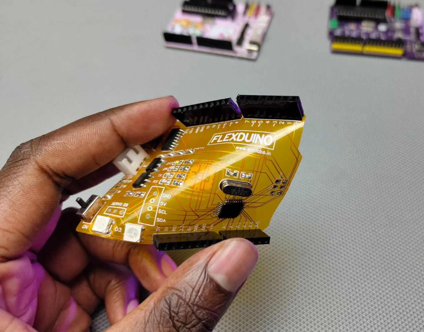


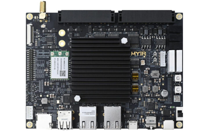
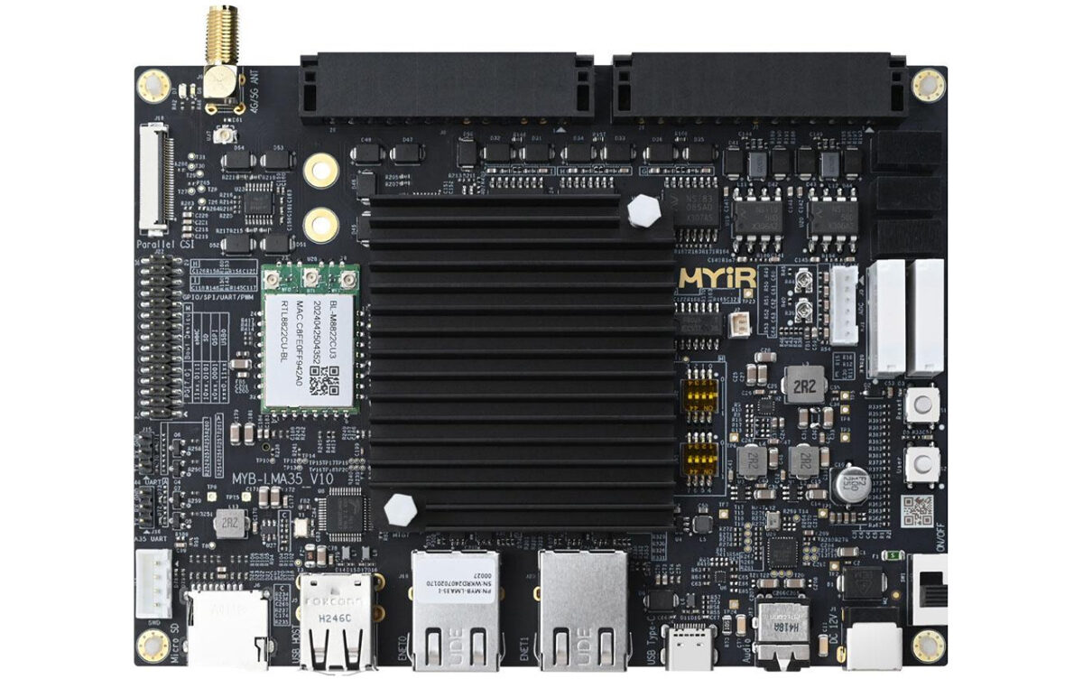

")


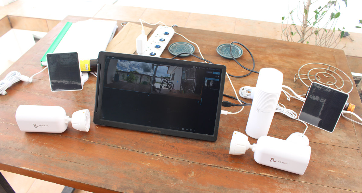


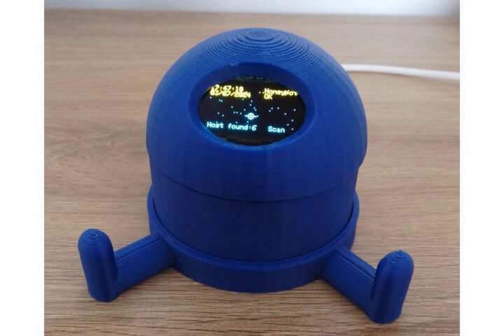
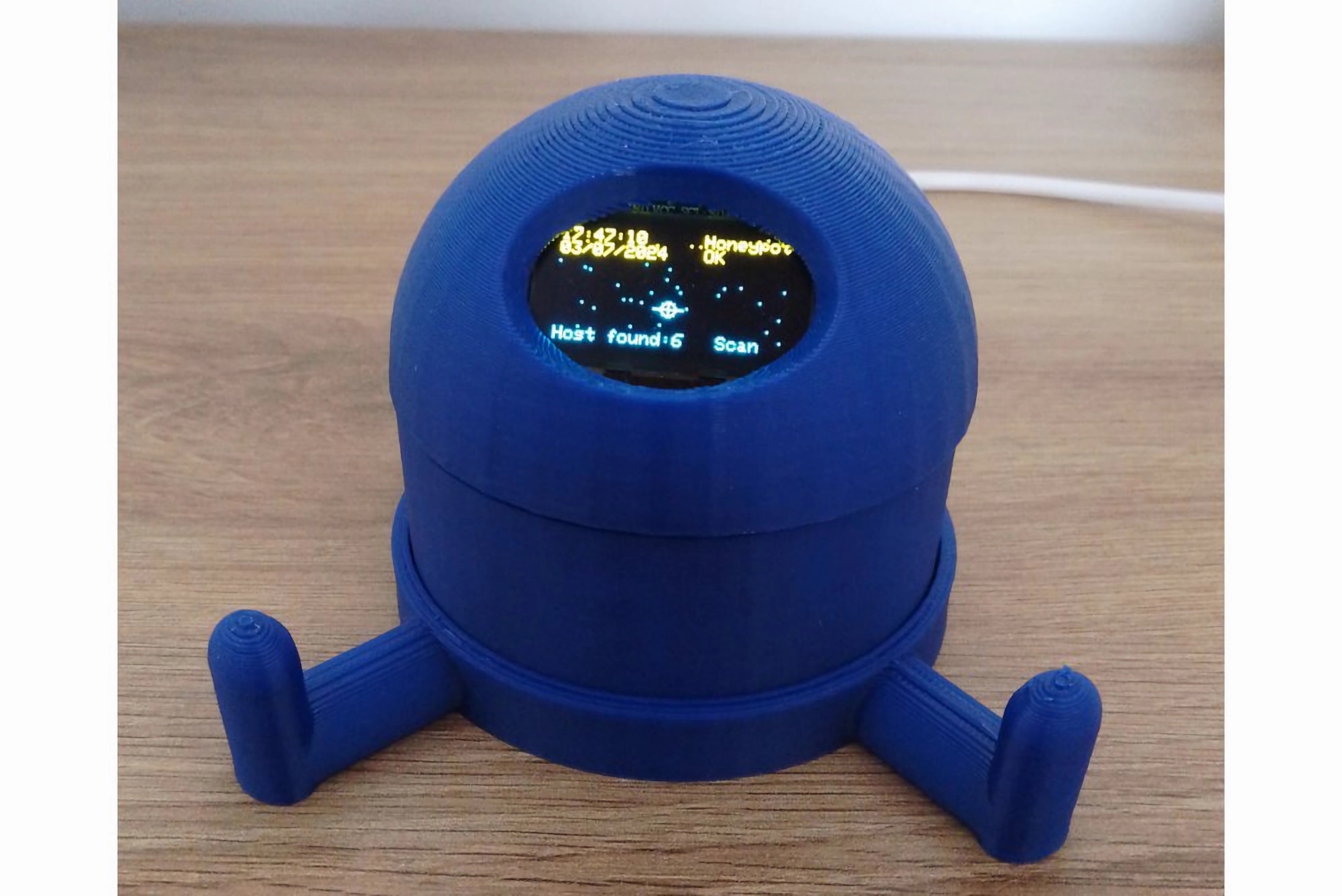


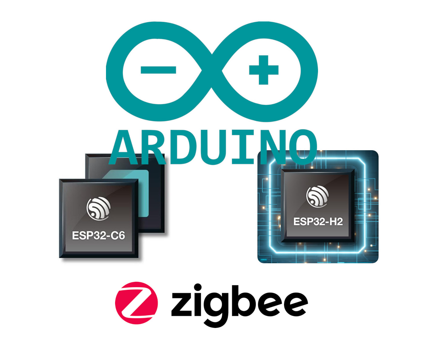
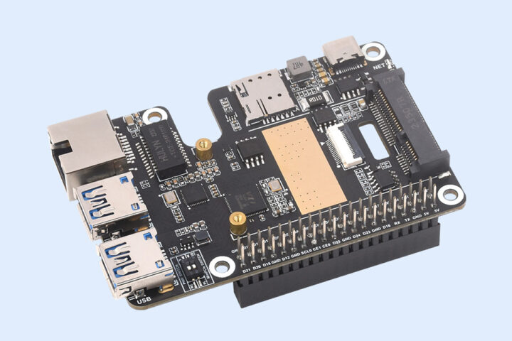


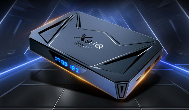


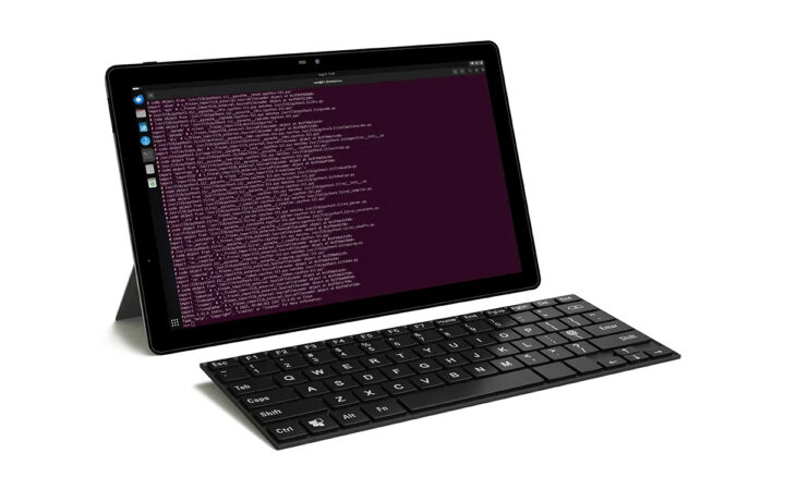


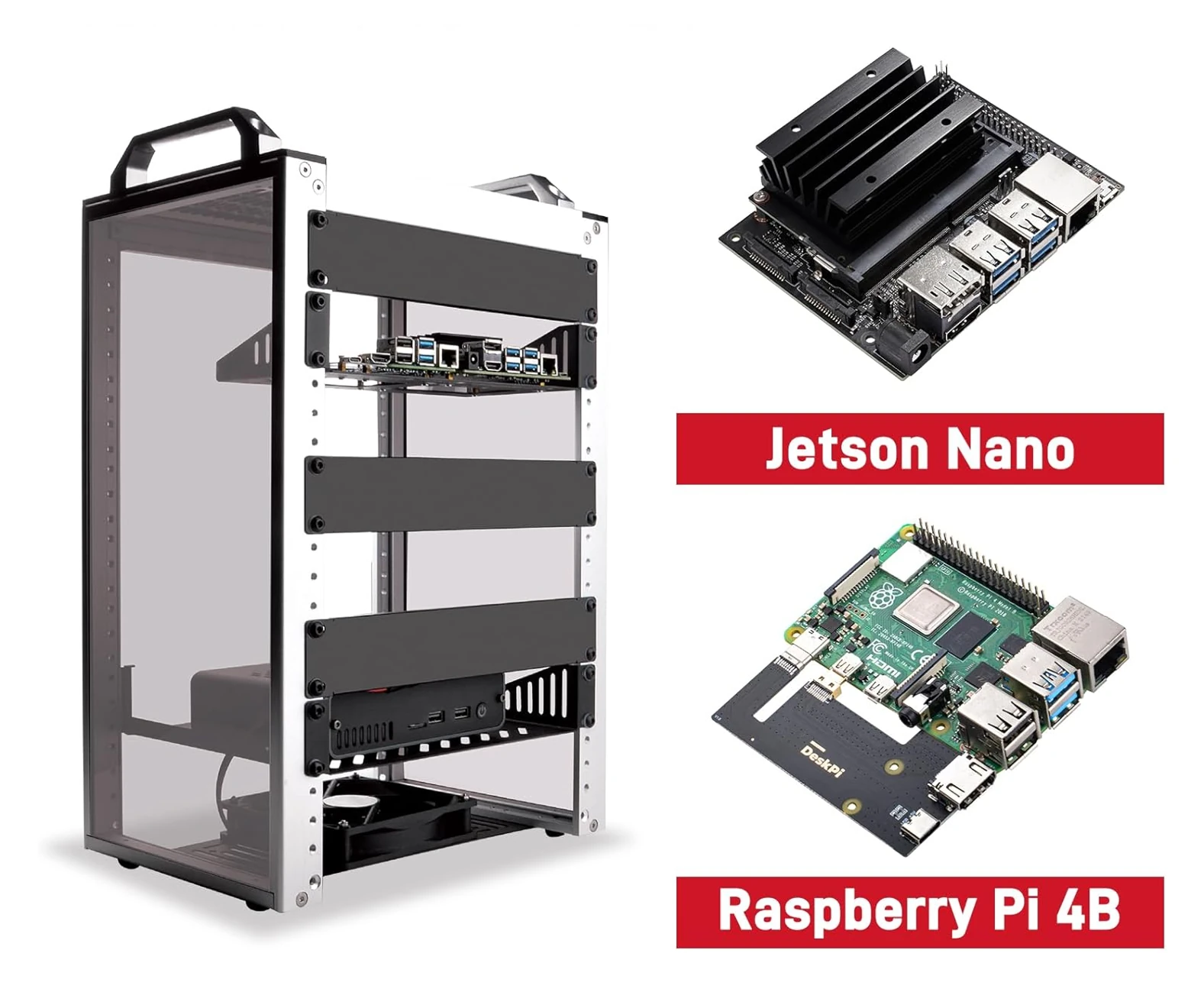


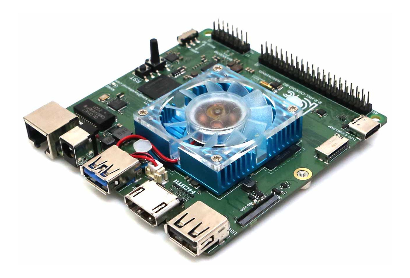


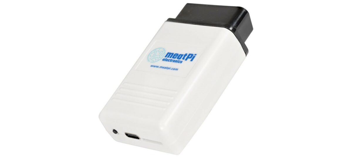


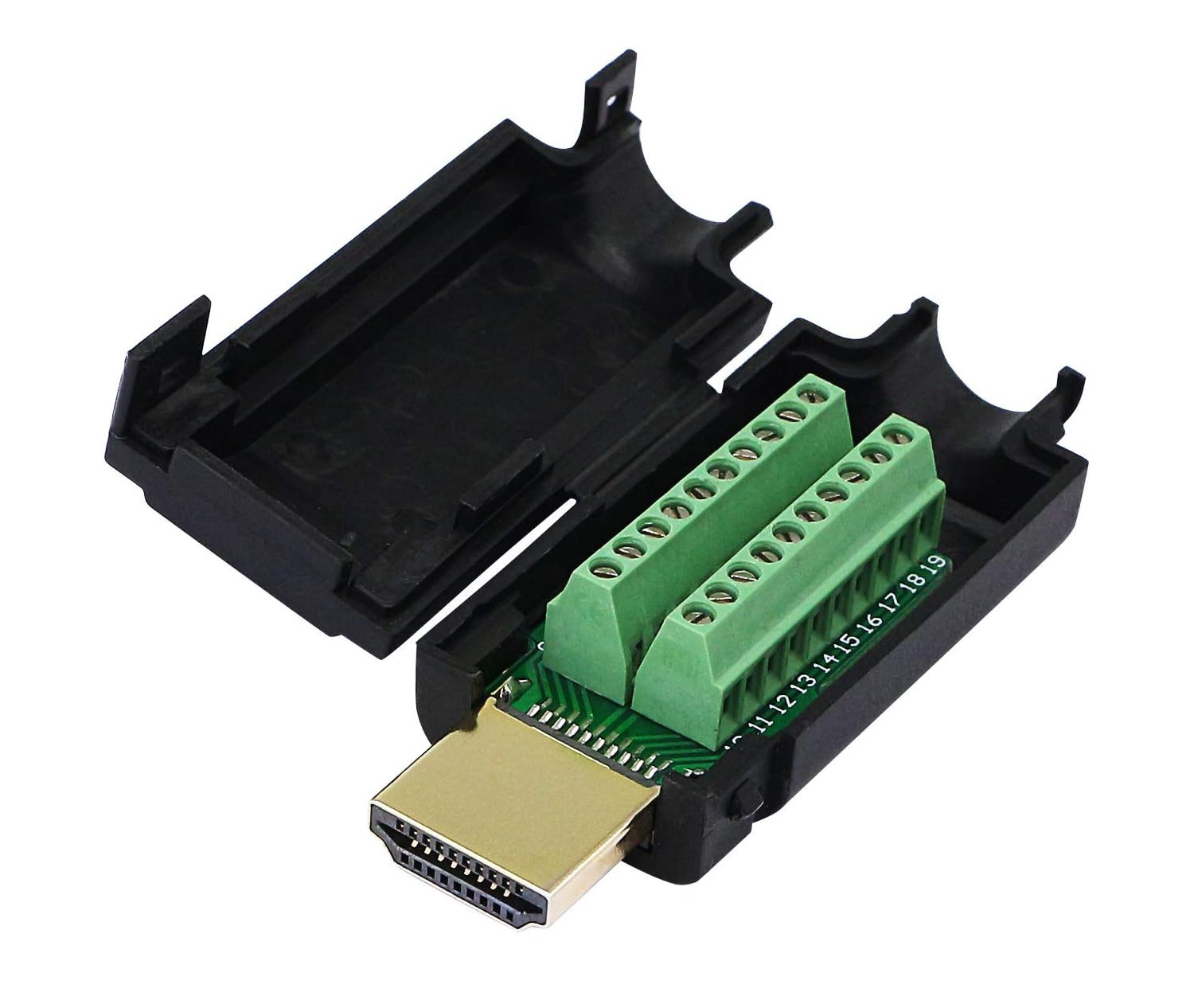


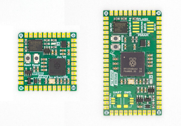
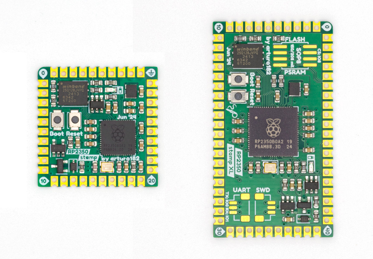


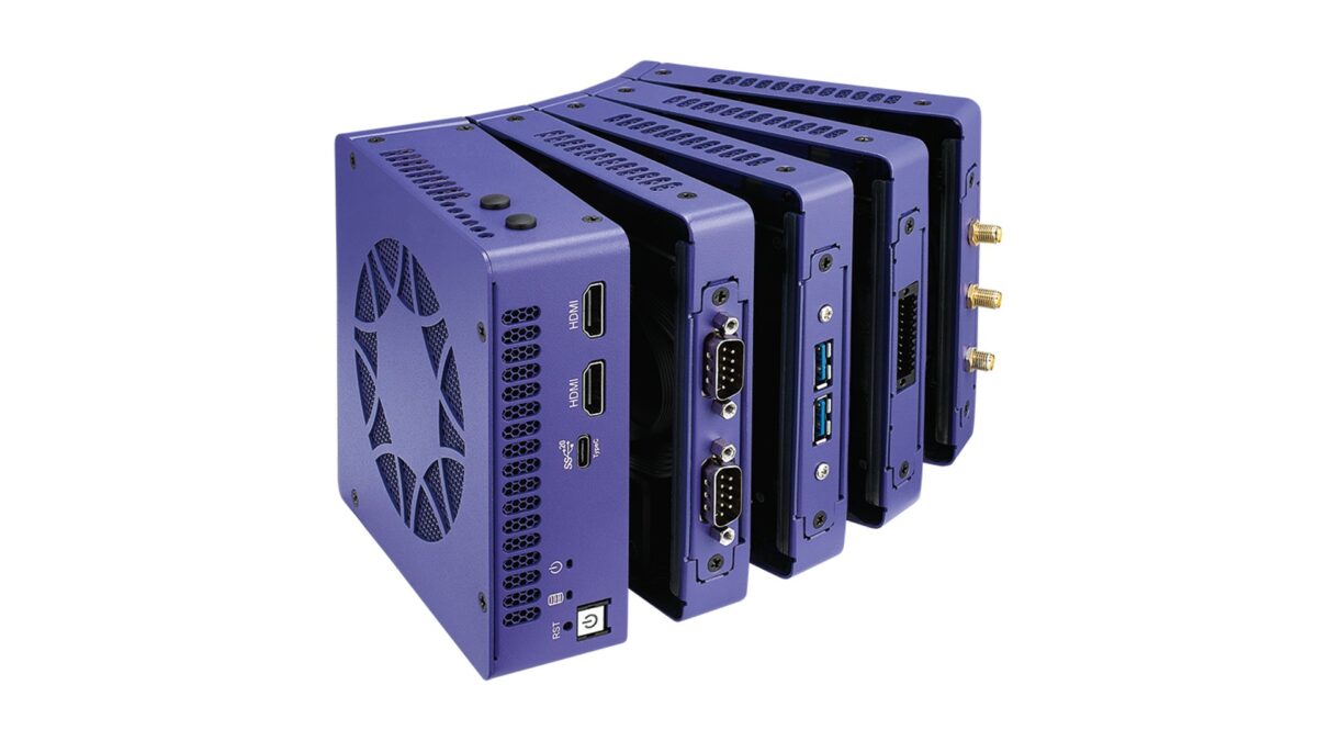


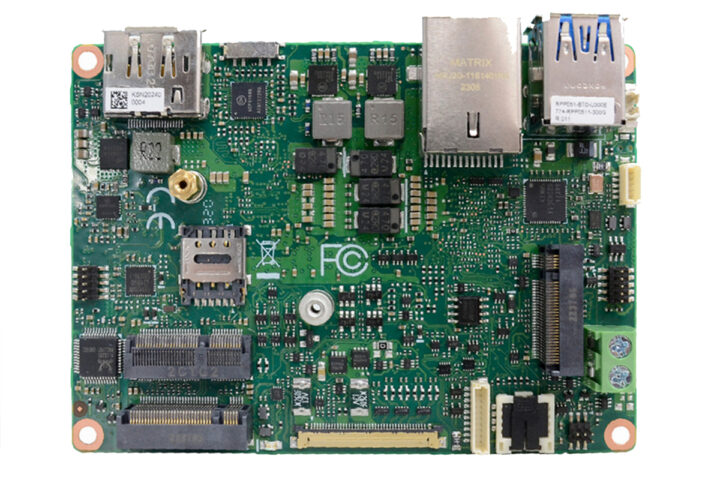


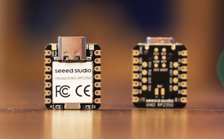


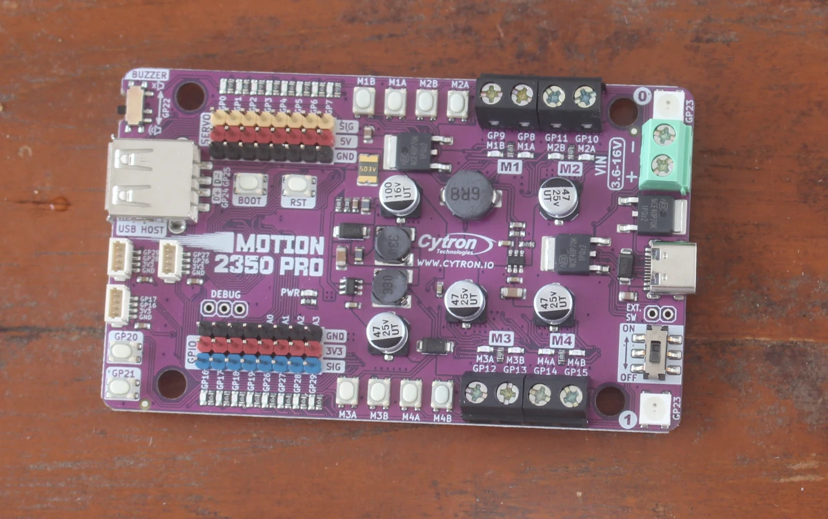


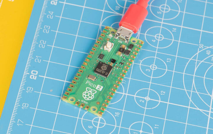
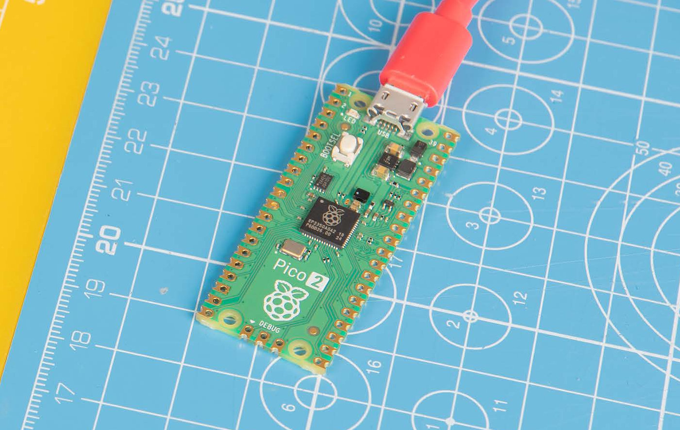


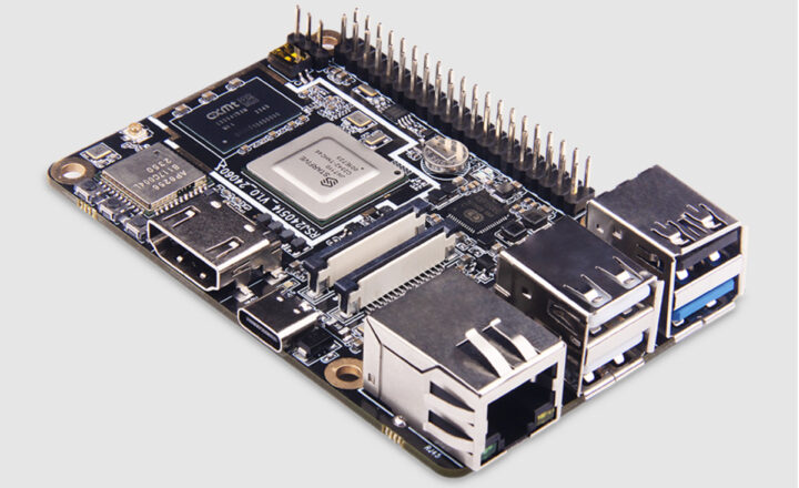
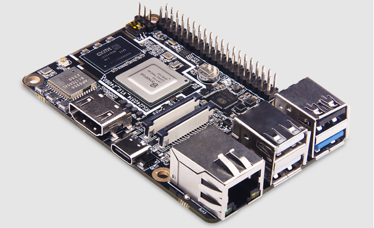


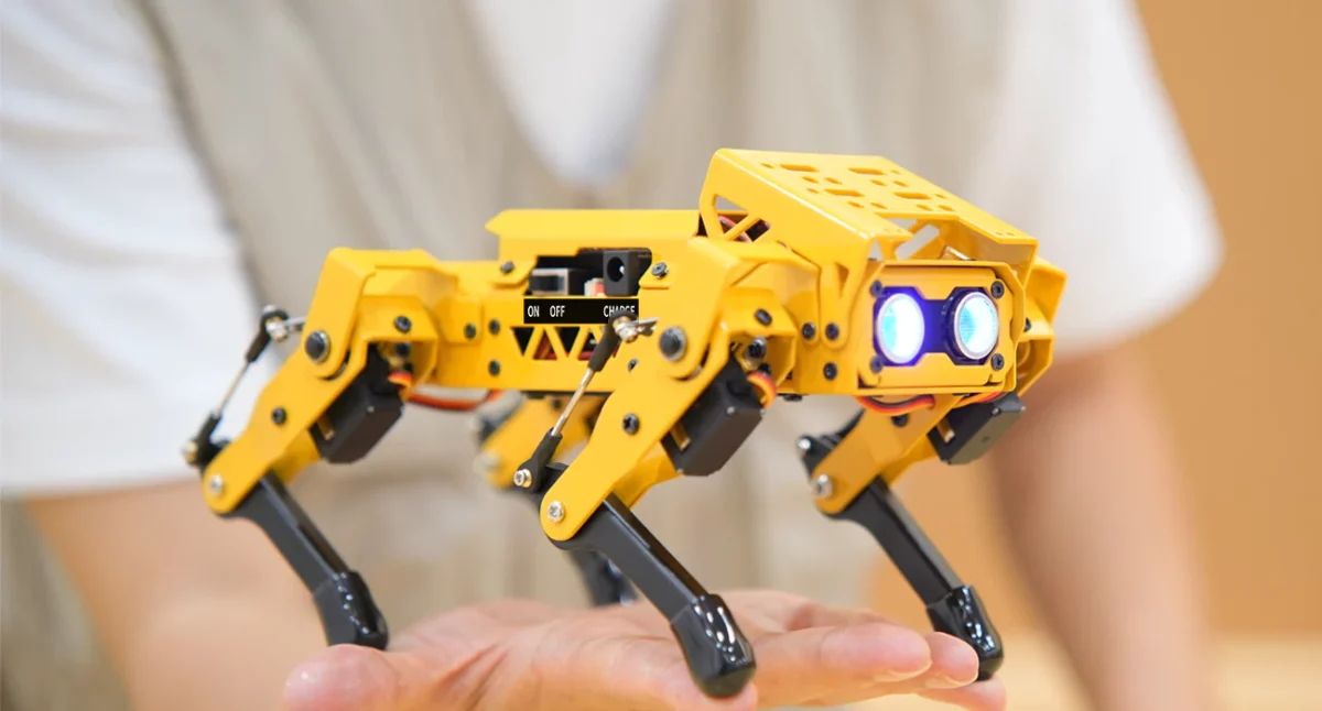


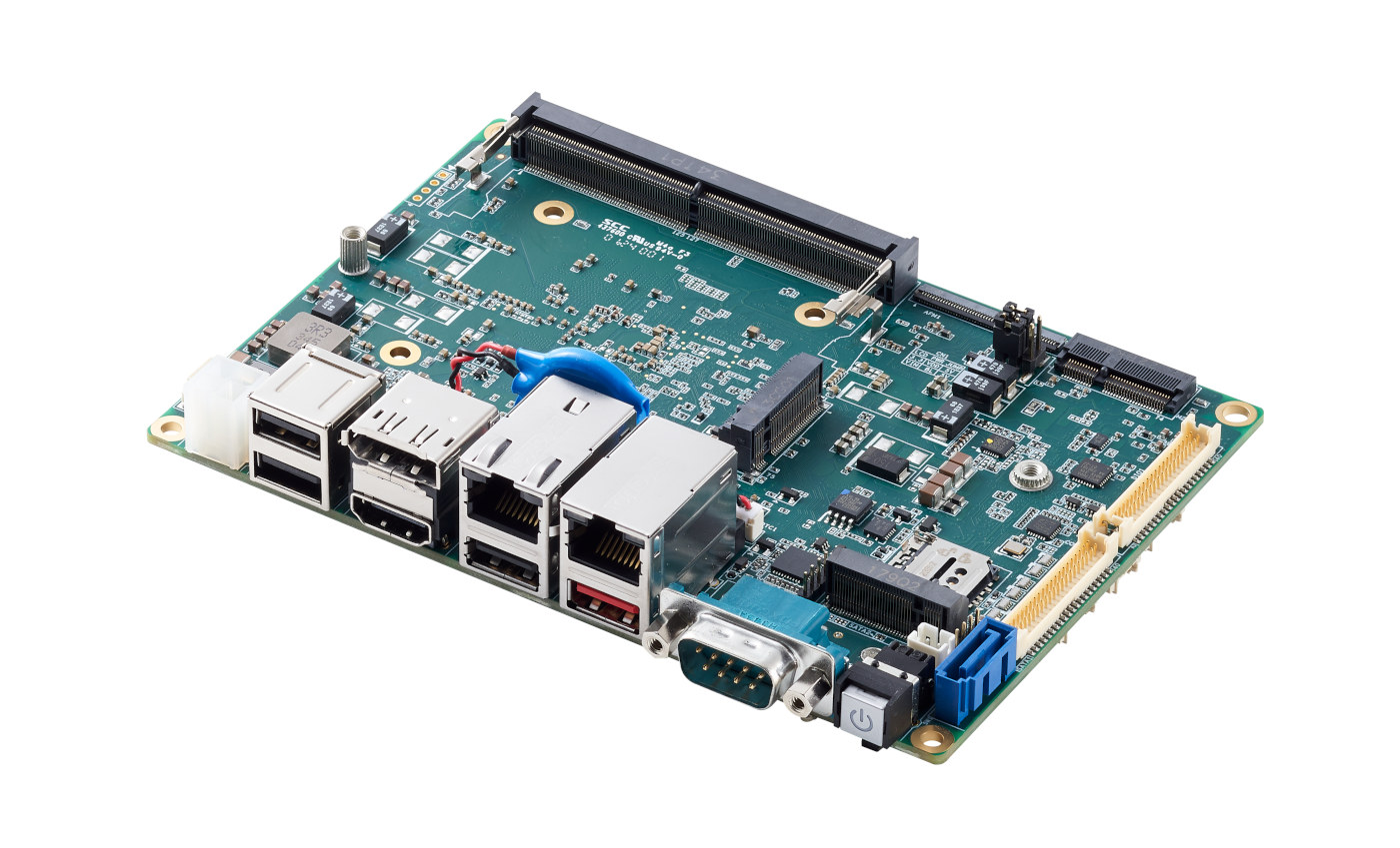


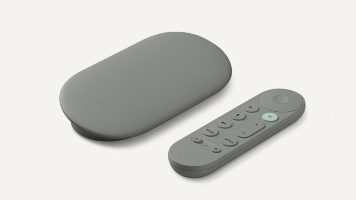
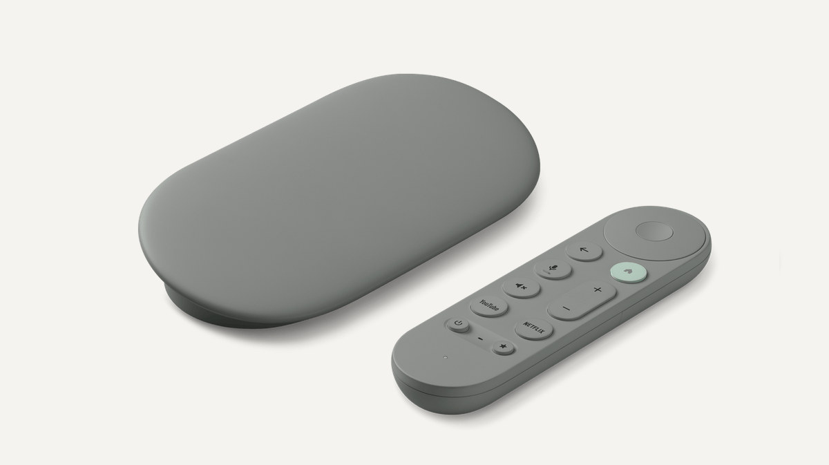

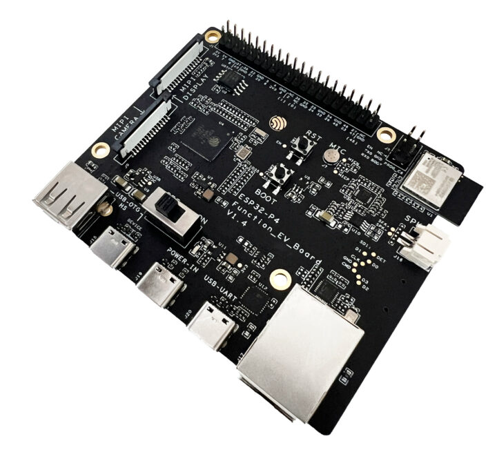


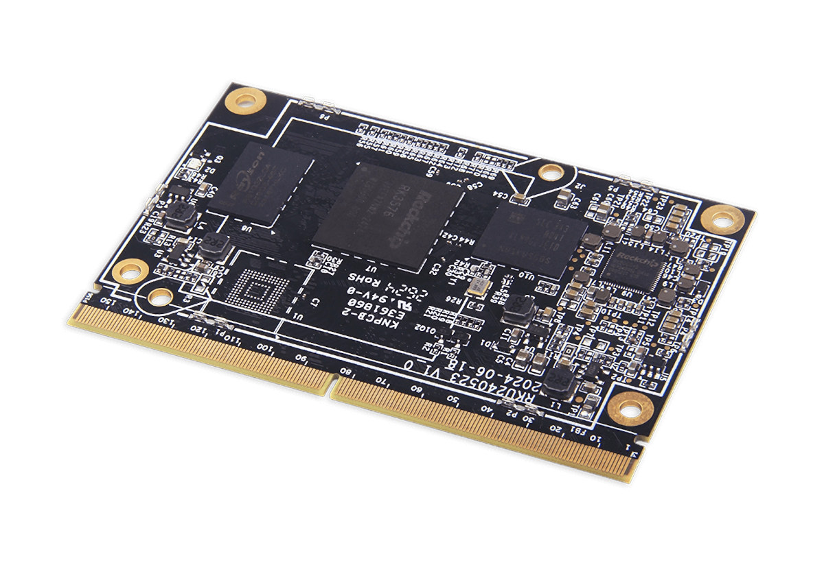


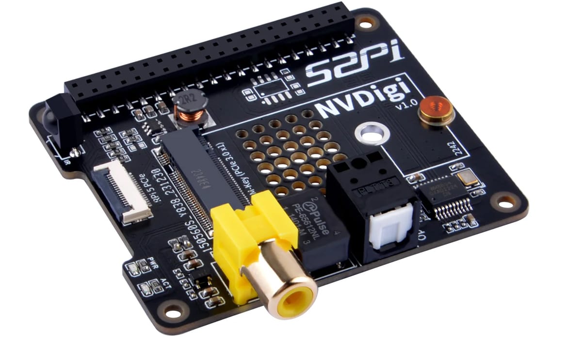


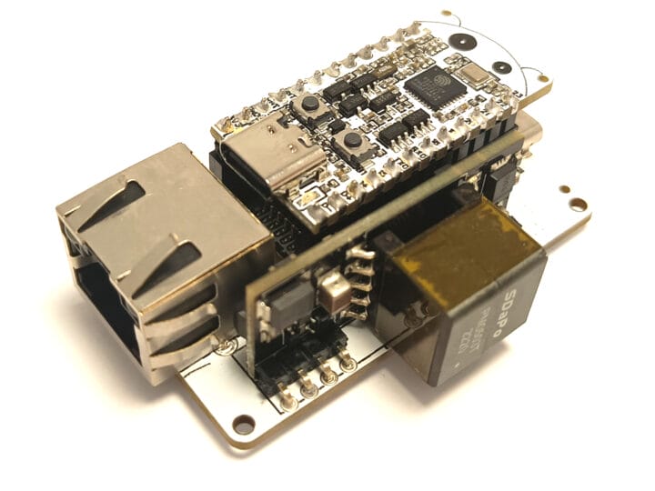


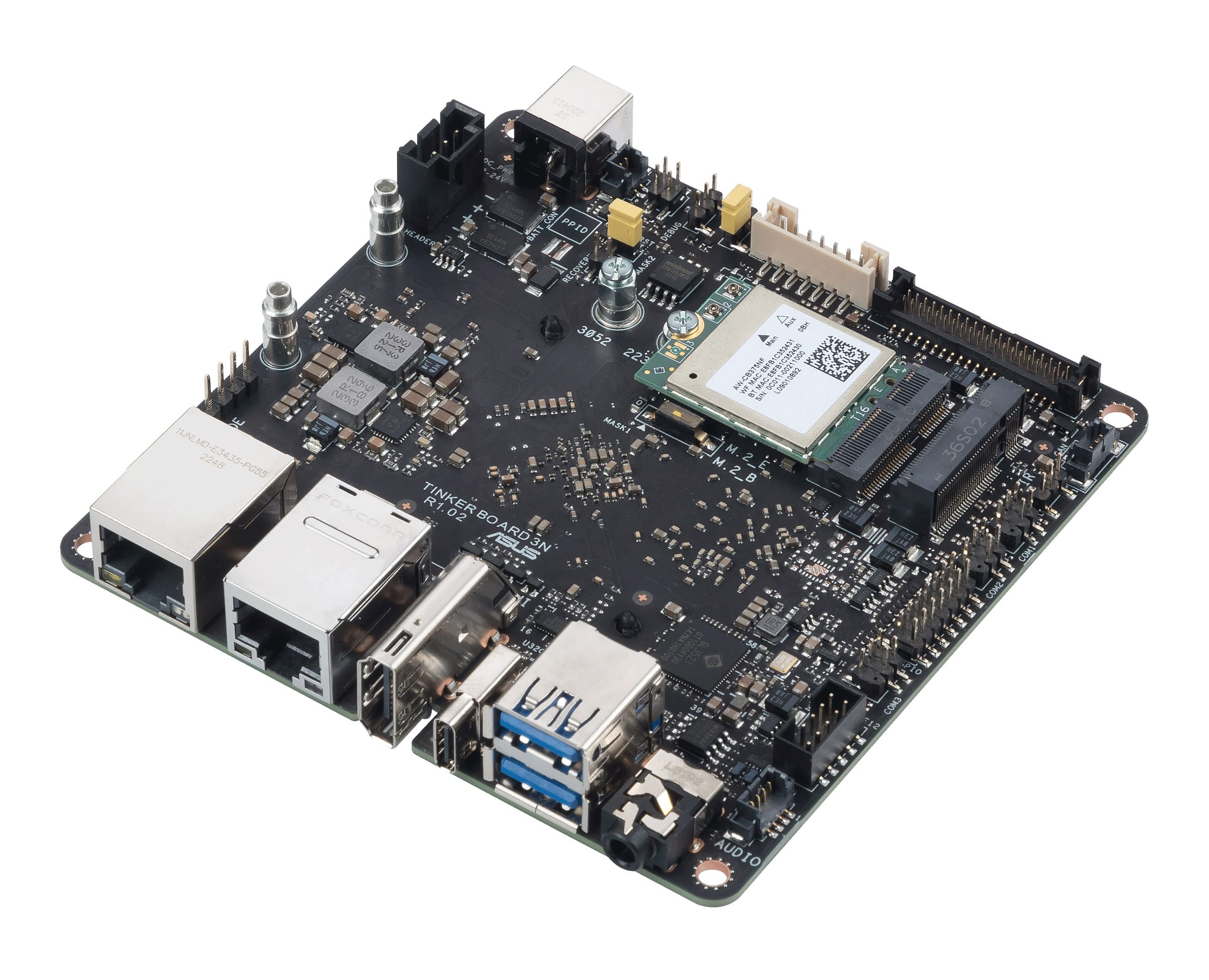


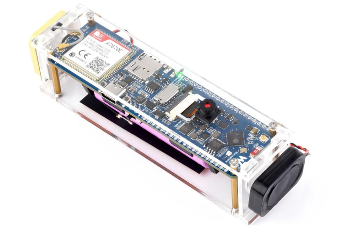


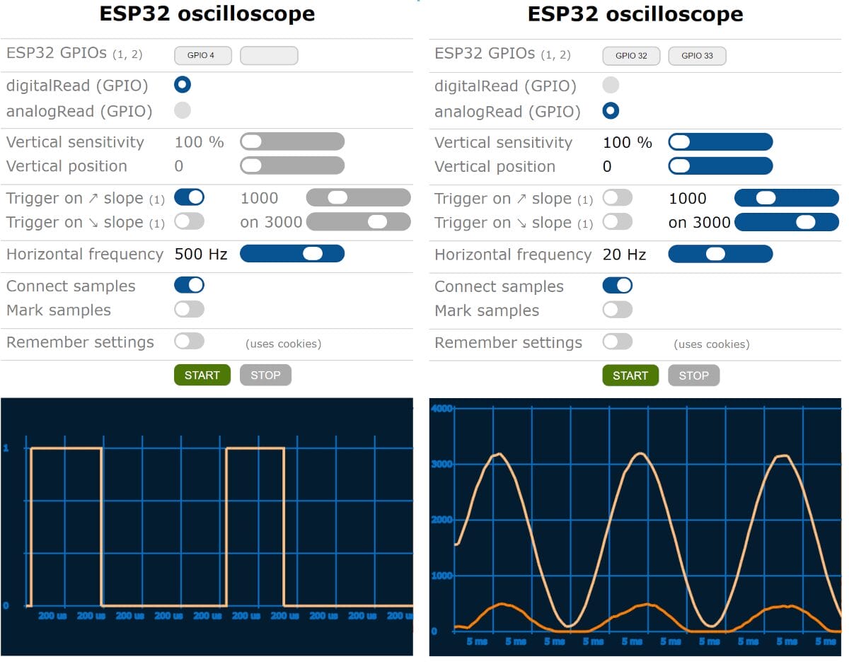


")