xMEMS Labs XMC-2400 is a vibration-free, solid-state micro cooling fan-on-a-chip that’s just 1mm thin and designed to cool the processor, other chips, and batteries on space-constraints devices such as smartphones, tablets, extended reality headsets, laptops, as well as SSDs.
The XMC-2400 can deliver up to 39cc/sec airflow and up to 1,000Pa back pressure per instance while remaining inaudible and only consuming an estimated 30mW. It’s also rated IP58 for water and dust resistance. It leverages the manufacturing process the company has been using for its ultrathin MEMS speakers.
xMEMS XMC-2400 specifications:
Top-venting and side-venting packages for flexible integration in different system form-factors
Bi-directional flow rate, adjustable up to 39cc/sec
Inaudible; all mechanical operation is at ultrasonic frequencies
Power consumption – 30mW (estimated)
Dimensions – 9.26 x 7.6 x 1.08 mm
Weight – 150 mg
SMT-reflowable
Ingress Protection – IP58
Cooling process
Two packages will be offered:
XMC-2400-S – Side-Vented Package supports chip-stacking with the application processor; A “heat spreader” can be used as a lid to transfer heat from the “heat source”. Cold air flows from bottom vent holes (8 of them), striking the “heat spreader” and discharging the “hot air” to the side opening.
XMC-2400 – Top-Vented Package which lets the airflow go through slits on the lid to blow on the ”heat source” to cool down
It’s not the first time we’ve come across a “solid-state active cooling solution“, as we covered the Airjet cooling chips last year which can dissipate up to 5W or 10W depending on the model and are suitable for laptops and mini PCs such as the Zotac PI430AJ Pico.
The xMEMS XMC-2400 is a much smaller chip better suited for systems with lower power dissipation but that may still benefit from cooling for sustained performance, improved reliability, etc… xMEMS Labs provided a comparison table between the XMC-2400 and the AirJet Mini Slim (5W dissipation).
xMEMS vs AirJet comparison
While the raw numbers are still better for the Airjet Mini, the XMC-2400 micro cooling fan-on-a-chip is impressive when taking into account the relative performance, as it’s only a 1/39th in size, delivers 16 times better cooling efficiency, and consumes significantly less power.
One benefit of the Airjet chip is that it’s available now, although it’s not used extensively so far likely due to its price (it adds $100+ to the aforementioned Zotac mini PC) and power consumption (1W per chip). The xMEMS XMC-2400 micro cooling fan-on-a-chip still has to prove itself, and samples are only expected in Q1 2025 with mass production following suit in 2026. Additional information may be found on the product page and in the press release. The xMEMS XMC-2400 will also be demonstrated to “lead customers and partners” next month during live events in Shenzhen and Taipei.
ALLPCB is an ideal PCB manufacturer for PCB professionals and businesses thanks to additional customization options compared to competitors, monthly discounts for business users, and post-delivery payment options, besides ultra-fast delivery services and quality assurance services.
ALLPCB customization options
ALLPCB excels at higher specification boards and more complex PCB designs, which is why ALLPCB provides more customized quote options than competitors. Let’s take JLCPCB, one of ALLPCB’s main competitors, as an example starting with “Surface Finish” options for FR-4 material.
JLCPCB PCB specifications
JLCPCB offers three options, namely HASL (with lead), LeadFree HASL, and ENIG, but ALLPCB offers a total of 12 different surface finish options.
That would the the same first three as in JLCPCB, but also
ALLPCB also offers a PTH (Plating Through Hole) copper thickness option from
You can discover more customization options such as selecting our prepreg for various applications on ALLPCB’s online quote system.
A business-friendly PCB manufacturer
ALLPCB has a business verification program designed to enhance efficiency and reduce costs for business users. It offers business users monthly discounts and post-delivery payment options. After the verification, a business can have net 30-day payment terms to help with their cash flow. Also, they can enjoy ALLPCB prototyping services each month for a minimum cost of 1$.
ALLPCB’s PCB batch order prices are highly competitive. Aluminum PCBs start at $50 per square meter, and 6-layer PCBs start at $110 per square meter.
The company also recognizes the importance of time to market. ALLPCB offers significantly faster delivery times compared to industry standards. For example, 6-layer board batch orders (under 5 square meters) can be produced in just 3 days, while aluminum PCB batch orders (under 10 square meters) are produced in 2 days. This is 3-5 days faster than what competitors typically provide.
Quality assurance is equally important and all solder masks are even and thick, PCBs have smooth edges, and silkscreens are clear and accurate.
Give ALLPCB a try for just $1 with 1-6 layer PCB
If you think your business might benefit from ALLPCB PCB manufacturing services, you can have the opportunity to test the service for just $1 for an order of 5 pieces with up to 6 layers and a size of up to 150x100mm. You can check out the ordering process in our previous article about the promotion.
Banana Pi BPI-WiFi6 Mini is an inexpensive WiFi 6 and dual Gigabit Ethernet router board with an M.2 Key-B socket and Nano SIM card slot to add 4G LTE or 5G cellular connectivity.
Optional 4G LTE or 5G cellular connectivity via M.2 Key-B socket (USB) and nano SIM card slot; tested with Quectel RM500U 5G module and Quectel EM05 4G LTE module
USB – 1x USB 3.0 port
Debugging – 3-pin debug UART header
Misc
Reset button
Fan connector
Power Supply – 12V DC via USB-C port
Dimensions – 65 x 65mm
Banana Pi provides an OpenWrt image (fork) for the board which can be found on the wiki. But note the board will likely never be part of upstream OpenWrt.
Since the form factor is the same as the more powerful (and expensive) Banana Pi BPI-R3 Mini, the cases for the latter can be reused with the Banana Pi BPI-WiFi6 Mini SBC.
The Banana BPI-WiFi 6 Mini board is sold on AliExpress for $29.60 plus shipping, a price that is somehow about the same as the Banana BPI-WiFi6 router with five GbE ports. The main advantages of the Mini board are the USB 3.0 port and the M.2 B-Key socket for 4G LTE/5G cellular connectivity. You can buy the case above from third-party sellers for about $21 and up which makes it much less attractive as a complete router… A complete set with the board and enclosure can be found on Amazon for $69.
Seeed Studio has added yet another member to their XIAO board family with the XIAO RA4M1 powered by Renesas’ RA4M1 32-bit Arm Cortex-M4 MCU. This compact board includes 256KB Flash, 32KB SRAM, a 14-bit A/D converter, a 12-bit D/A converter, a CAN bus interface, and onboard charging circuitry. It’s designed for low-power, battery-powered applications.
The company started the XIAO family with the Seeeduino XIAO (Microchip SAMD21G18) in 2020, and since then they’ve made several other variants with different processors including the XIAO RP2350, XIAO RP2040, XIAO ESP32C3, XIAO ESP32S3, XIAO ESP32C6, and the nRF52840-based XIAO BLE. Feel free to check them out if you are interested in these boards.
XIAO RA4M1 Specification:
Microcontroller – Renesas RA4M1 (R7FA4M1AB3CFM) as found in Arduino UNO R4
CPU – Arm Cortex-M4F operating at up to 48 MHz
Memory – 32KB SRAM
Storage
256 KB code flash memory
8 KB data flash memory
USB – 1x USB type C port for power and programming
Expansion I/Os
2x 7-pin 2.54mm pitch headers and castellated holes with
Up to 11x GPIO
1x SPI, 1x UART, 1x I2C
1x CAN Bus
Up to 6x 14-bit analog inputs
1x 12-bit DAC (on D0/P014, not shown on pinout diagram…)
The XIAO RA4M1, the 10th member of Seeed Studio’s XIAO family, is fully compatible with the Arduino IDE for easy project development and prototyping. It retains the classic XIAO design, making it ideal for space-limited projects like wearables or as a production-ready module for PCB designs. The company provides detailed instructions and a schematic diagram on its wiki page to help you get started.
Seeed Studio sells the XIAO RA4M1 in its official store for $4.99 without shipping charges. The company also provides two 7-pin headers in the package.
AAEON has just introduced the UP Squared 7100fanless single board computer powered by Intel Processor N-series CPUs (N97 or N100 by default) with up to 16GB LPDDR5 and 128GB eMMC flash in a compact 90 x 85.6mm form factor.
The SBC can drive up to three independent 4K displays at 60 Hz, features two RS232/422/485 interfaces, gigabit Ethernet, three USB 3.2 ports, and expansion options that include a 40-pin GPIO header, and two M.2 sockets for NVMe storage and WiFi/Bluetooth connectivity.
Certifications – CE/FCC Class A, RoHS Compliant, REACH
AAEON provides support for Windows 10 and 11, Ubuntu 22.04, and Yocto 5.1 for the board. The design is relatively similar to the earlier UP Squared Pro 7000, but the UP Squared 7100 is a little smaller and loses features such as SATA storage, a MIPI CSI camera connector, and an M.2 B-Key socket plus SIM card slot combo for 4G LTE/5G connectivity. Documentation should soon become available on the wiki.
As a community board, the UP Squared 7100 SBC is not sold through the AAEON website, but you’ll eventually find it for sale on UP Bridge the gap! website. The “Order Board” button is already there but currently points to a 404 page… The company also mentions that variants of the UP Squared 7100 with the industrial-grade Intel Atom x7000RE “Amston Lake” processor will be made available in Q1 2025. A few more details include a datasheet and a user manual can be found on the product page.
NanoPi M6 is a Rockchip RK3588S SBC (single board computer) that is also offered as a complete fanless HMI solution with a metal case and a 3.5-inch capacitive touchscreen display with 800×480 resolution.
The M6 is offered with 4GB to 32GB LPDDR5 memory, supports microSD, eMMC flash module, and M.2 NVMe SSD bootable storage, features one HDMI 2.1 port, two MIPI DSI connectors, two MIPI CSI camera connectors, gigabit Ethernet, an M.2 E-Key socket for WiFi and Bluetooth, and a 30-pin GPIO header for expansion among a few other ports and features.
CPU – Octa-core processor with 4x Cortex-A76 cores @ up to 2.4 GHz, 4x Cortex-A55 cores @ up to 1.8 GHz
GPU – Arm Mali-G610 MP4 GPU compatible with OpenGL ES 3.2, OpenCL 2.2, and Vulkan 1.2 APIs
VPU – 8Kp60 video decoder for H.265/AVS2/VP9/H.264/AV1 codecs, 8Kp30 H.265/H.264 video encoder
AI accelerator – 6 TOPS NPU
System Memory – 4GB, 16GB, or 32GB LPDDR5 at 2400 MHz
Storage
eMMC module socket supporting HS400 mode
MicroSD card slot with SDR104 mode support
M.2 M-Key socket with PCIe 2.1 x1 for NVMe SSDs
Video output
HDMI 2.1 port up to 7680×4320 @ 60Hz; RGB/YUV(up to 10bit) format
2x 4-lane MIPI-DSI connectors
Optional Display – 3.5-inch touchscreen LCD with 800×480 resolution and capacitive touchscreen connected to one of the MIPI DSI connectors
Camera input
4-lane MIPI-CSI V1.2 connector
4-lane MIPI-CSI D/C PHY connector
Audio
3.5mm jack for stereo headphone output
2.0mm PH-2A connector for analog microphone input
Networking
Gigabit Ethernet RJ45 port
Optional WiFi and Bluetooth via M.2 E-key socket with PCIe 2.1 x1 and USB 2.0 host
USB
1x USB 3.0 Type-A port
2x USB 2.0 Type-A ports
Expansion
M.2 Key-M socket for PCIe storage
M.2 Key-E socket for WiFi/Bluetooth (PCIe/USB)
30-pin 2.54mm GPIO header with up to 1x SPI, 6x UART, 3x I2C, 1x SPDIF, 4x PWM, 20x GPIO
Debugging – 3-pin header for serial console
Misc
2x user LEDs
2-pin RTC battery input connector for low-power HYM8563TS RTC IC
Buttons – MASK, Reset, Recovery, Power
5V fan connector
Power supply – 6V~20V input via USB-C with PD support
Dimensions & Weight
SBC – 90 x 62 mm (8-layer PCB) | 52 grams
Metal case – 94.5 x 68 x 30mm | 252 grams
Metal case + LCD – 99 x 68 x 31mm | 275 grams
Temperature Range – 0°C to 70°C
FriendlyELEC provides OS images for Debian 12 Core (headless), Debian 11 Desktop and Minimal, Ubuntu 20.04 Desktop, Ubuntu 22.04 Desktop and Minimal, Xubuntu 22.04, Android 12 TV, Android 12 Tablet, OpenMediaVault, and FriendlyWrt, a fork of OpenWrt. All images are based on Linux 6.1, and Ubuntu 24.04 support is coming soon. You’ll find those and other information in the wiki. I would expect the NanoPi M6 to benefit from the software work done on the earlier NanoPi R6S that we reviewed with Ubuntu 22.04.
The company stress-tested the NanoPi M6 in its metal case with or without display and the maximum CPU temperature was under 70°C, and since the board does not come with WiFi, they also provide a list of supported WiFi dongles. This information can be found on the product page where you can also purchase the NanoPi M6 for $70 and up depending on options. The top model with 32GB RAM, a 64GB eMMC flash module, a metal case, and a 3.5-inch touchscreen display goes for $205.
NanoPi M6 housed in a metal case with or without a display
PCB Studios has just launched the “Flipper Zero ESP8266 Deauther” adapter board for Flipper Zero that enables users to conduct de-authentication attacks on Wi-Fi networks. Running a modified version of SpacehuhnTech’s ESP8266 Deauther software, this board has a variety of actions for testing 802.11 wireless networks. Its primary function, deauthentication, sends deauthing packets to the target network, disconnecting devices from their 2.4 GHz Wi-Fi networks.
In our last post about Flipper Zero, we wrote about Flipper Add-On CANBus a CAN bus hacking tool that can sniff, send, and log CAN bus packets. Other than that we have seen similar tools like the M1 multitool and HackBat which can be considered as Flipper Zero alternatives with STM32H5 and Raspberry Pi RP2040 MCUs and Wi-Fi connectivity. We have also written about various ESP8266 and ESP32-based Deauther tools like the DSTIKE Deauther Watch X, the Cheap Evil Tech Deauther board, and ESP32 Marauder Pocket Unit v2 all of which are wireless penetration devices. Feel free to check them out if you are interested in those topics.
The board can be considered a GPIO board and a standard ESP8266 NodeMCU module sits on top of that PCB, so there is an option to buy the PCB only or the PCB with a soldered NodeMCU ESP8266 module on top of it.
PCB Studios mentions that to use this board, you must have the Flipper Zero app; however, if you are using firmware such as Rougemaster or Xtreme, the application comes preinstalled. Otherwise, you need to follow the instructions on GitHub to install the app, and as far as I understand, there is no way to install the app through Flipper’s app store.
This software allows you to easily perform a variety of actions to test 802.11 wireless networks including scan, attack, Packet monitor, and more which makes it a versatile tool for penetrating testing applications.
Flipper Zero ESP8266 Deauther board with and without ESP8266-based Node MCU module
The Flipper Zero ESP8266 Deauther is priced at around $24.98 with the soldered ESP8266 module and $19.99 without the soldered module, both boards are available at the Tindie store.
The ANAVI Dev Mic is an open-source microphone board from ANAVI Technology in Plovdiv, Bulgaria powered by the Seeed Studio XIAO RP2040 module and an omnidirectional digital microphone from STMicroelectronics. It is a compact and affordable product that outperforms USB microphones in artificial intelligence and machine learning voice applications.
The design is simple and unassuming, with the Seeed Studio XIAO RP2040 module in the center, surrounded by a USB-C port for power and programming and 9 GPIO pins for extensibility. The STMicroelectronics MP23DB01HP microphone (MK1) is mounted on the top of the board with a small hole on the bottom. It is a compact, low-power, digital MEMS microphone capable of capturing sounds from different directions with very low distortion. It uses a PDM (Pulse-Density Modulation) interface created via the programmable inputs/outputs (PIO) on the RP2040.
The ANAVI Dev Mic is applicable for conducting AI/ML research, building a voice recognition platform, or creating interactive experiences. The GPIO pins on the board can be used to extend its functionality with buttons, LEDs, and sensors.
The ANAVI Dev Mic is entirely open-source. The hardware schematics and case files are available on GitHub under the Creative Commons Sharealike license. The firmware is based on the open-source Microphone Library for Pico and the Raspberry Pi Pico C/C++ SDK. It can be connected to a PC or a single-board computer via the USB-C connector on the board.
The crowdfunding project is currently running on Crowd Supply and has attracted few backers so far. The Dev Mic is priced at $25 for the board, enclosure, and screws and nuts to hold it in place. Shipping is free within the United States but costs $12 for the rest of the world. Orders are expected to ship by November 17.
The Radxa X4 is a single-board computer that uses an Intel N100 processor instead of an Arm-based SoC found in most SBCs and also embeds a Raspberry Pi RP2040 microcontroller for GPIO control. What’s interesting is that the Radxa X4 is a small computer board with a similar form factor as the Raspberry Pi 5 SBC, but benefits from the higher performance of Intel “Alder Lake-N” Processor N100 CPU and out-of-the-box compatibility with most operating systems, except for specific features such as GPIOs.
The Intel N100 board also comes with a built-in M.2 M-key socket (so no need for an extra HAT) that supports higher speed storage thanks to a PCIe 3.0 x4 interfaces, as well as WiFi 6 connectivity, making the Radxa X4 an interesting option for those looking for a small, capable computer board for home, IoT, or industrial use. The company sent us a full kit with the board, heatsink case, 30W power supply, and 128GB M.2 NVMe SSD, and in the first part of the Radxa X4 review, we will go through an unboxing, assemble the kit, and install Ubuntu 24.04.
Radxa X4 kit unboxing
We got five boxes in the package sent by Radxa for the heatsink case, the Radxa X4 board itself, a USB-C to USB-C cable, a Radxa Power PD 30W power adapter, and an NVMe SSD.
The provided SSD is a tiny Samsung PM991 M.2 2230 NVMe SSD with 128GB capacity (model MZ-9LQ1280).
The kit also includes a “Radxa Power PD 30W” power adapter compatible with the USB PD standard, which can output up to 5V @ 5A, 9V @ 2A, and 12V @ 2.5A. It supports AC input from 100V-240V. It has a clear laser data emission. The adaptor’s legs are foldable, which is great for portability, but be careful when plugging it into the socket because you might accidentally break a leg. The Radxa-branded USB-C to USB-C cable looks of good quality.
A first look at the Radxa X4 board reveals a design similar to the Raspberry Pi 5 with the four USB Type-A ports, the Ethernet port, micro HDMI video outputs, and the USB-C power port placed in the same location as the Pi 5 SBC. However, upon closer inspection, we found extra connectors and features on both sides of the Intel N100 SBC, such as a WiFi 6 module, an M.2 socket for an M.2 2230 NVMe SSD, and an RTC battery.
The bottom side of the board features the Intel N100 CPU which may be more practical for various cooling solutions. We’ll also find a SKhynix H58G66BK8BX067 RAM chip (8GB LPDDR5) and an MPS2105 step-down converter.
Looking more closely at some of the components on the top of the board, we’ll find the Azureware AW-XM548NF WiFi 6 and Bluetooth 5.2 module (Realtek RTL8852BE-based) that we previously found in the GEEKOM Mini Air12 mini PC also powered by an Intel N100 processor.
We can also see a Raspberry Pi RP2040 microcontroller close to the GPIO header, a Realtek ALC269 audio codec close to the 3.5mm audio jack, and an unpopulated eMMC flash footprint. Future versions of the Radxa X4 will come with or without eMMC flash, but our sample does not have built-in storage, so the only options are to boot with a USB drive or an M.2 2230 NVMe SSD.
Radxa X4 heatsink case assembly
The heatsink set with a fan installed on top doubles as a case for the board.
You can loosen the screws to separate the heatsink set and the case frame before assembly, and there’s also a thermal pad for the processor used to further improve cooling. We installed it before taking the photo below.
From there, the assembly is straightforward. First place the Radxa X4 board so that the N100 processor is in contact with the thermal pad, tighten the screws, connect the fan connector, and reassemble the cover.
It is worth noting that when the build is complete, the RTC battery will just hang and touch the desk since we have to turn the case upside down so that the fan faces up. Some dual-sided tape could help.
The cooling fan is also connected through a 2-wire cable, so although the Radxa X4 board can adjust the fan speed, it cannot read the fan speed.
We also found a gap between the thermal pad and the CPU, so we added an extra thermal pad to make sure cooling works in an optimal manner.
You’ll find the Radxa X4 specifications in our previous article, so we won’t reproduce them in this review.
NVMe SSD installation and BIOS
Since the Intel N100 is a standard x86 processor, you can install any operating system like you would on a standard computer. Since there’s no built-in storage, we had to install the NVMe SSD provided with the kit before installation an operating system.
We then connector an HDMI monitor, a USB keyboard, and a USB mouse for a quick test. We pressed the F2 button on the keyboard to enter the BIOS setup page with has some basic information as shown in the picture below.
Interestingly, the Project Version is shown as TESTG117 and the M/B name is TEST-N100, so Radxa may have used the test BIOS from Intel (for some reference design).
We could also confirm the SAMSUNG NVMe SSD was correctly detected in the Advanced section of the BIOS.
We also set the system date/time, and we’ll soon be able to boot the system with a bootable USB drive out selected operating system: Ubuntu 24.04 Desktop 64-bit.
Ubuntu 24.04 installation on Radxa X4
We just downloaded the standard Ubuntu 24.04 Desktop AMD64 ISO from the Ubuntu website, as there’s no need to select a specific image as we would have had to do for an Arm or RISC-V target. After selecting the USB drive in the BIOS we got the desktop and started the installation without issues.
We selected the NVMe SSD as the installation medium for Ubuntu 24.04 since that’s the only option.
The installation process took no time, and we did not encounter any problems during the Ubuntu 24.04 installation on the Radxa X4 board.
We’ll now check some basic system information below.
Everything is properly detected and the CPU idles at just 44°C. That’s a good sign about the cooling ability of the heatsink case, but we’ll do further testing under stress in the second part of the Radxa X4 review.
Summary of tests so far
The Radxa X4 is an x86 single board computer with a form factor that is similar to the Raspberry Pi 5 and suitable for home usage, IoT, edge computing. smart kiosks, and so on mostly because it can support a range of operating systems out-of-the-box.
We also expect new versions to come out soon based on Amstom Lake that should be suitable for a wider industrial operating temperature range. Testing the 40-pin GPIO header will be interesting too, but based on the documentation, it should be like having a Raspberry Pi Pico connected to the computer through USB and UART.
We would like to thank Radxa for sending the X4 SBC and accessories for review. The Radxa X4 is currently out of stock on AliExpress, but it can be purchased on Arace for $80 and up, and we can also see some models with 64GB or 128GB eMMC flash. In the second part of the review, we plan to compare the Radxa X4 to the Raspberry Pi 5 in terms of features and performance in a way similar to what we did when comparing the Raspberry Pi 5 to Intel N100 mini PCs, but this time it will include testing the GPIO header as well.
The MoreSense MS-06 is an ESP32-S3-based air quality monitor that takes CO², temperature, and humidity readings through a Sensirion SCD40 sensor which offers reliable performance and a lifespan of more than ten years.
The MS-06 monitor’s results are identical to the Aranet4’s (considered best-in-class), putting it in a pretty good spot accuracy-wise. It is the latest entry in the MoreSense line of air quality monitors and comes with a more compact design and a touchscreen display. The built-in web server runs an interface that displays measurements, historical data visualizations, setup options, and firmware updates. Operation is completely local; sensor data can be stored on the device or a microSD card.
The MoreSense MS-06 air quality sensor can be used to control a ventilation system, contributing to significant energy savings. This can be achieved through your home automation system or by using a smart plug.
MoreSense MS-06 specifications:
Microcontroller – ESP32-S3 SoC, dual-core XTensa LX7 @ up to 240 MHz; 512KB SRAM; Integrated 2.4GHz Wi-Fi and BLE
Display – 2.8-inch resistive touchscreen
Sensor – Sensirion SCD40 sensor, based on photoacoustic NDIR (non-dispersive infrared) technology
Dimensions – 114 x 68 x 35 mm (including stand), 104 x 68 x 24 mm (excluding stand)
The air quality sensor can be connected to a Wi-Fi network and linked to a home automation system via MQTT or REST. It supports Domoticz, Home Assistant, and Homey (via HomeyDuino).
According to the maker, the MoreSense air quality sensor will be available on Tindie from August 20th. It is priced at $119 and comes with a stand, stylus pen, USB adapter, USB cable, an enclosure, and the manual. The optional 2000mAh LiFePO4 battery will set you back about €10 or $11 extra. Shipping is free for buyers in the Netherlands and direct support from the maker is available. Buyers are also assured a one-year warranty and money-back guarantee.
The Raspberry Pi 5 has now a cheaper variant with 2GB of RAM going for just $50 following the launch of the Broadcom BCM2712 SBC in October 2023 with either 4GB or 8GB LPDDR4X-4267 SDRAM for respectively $60 and $80.
At the time of the release, we also noted that cheaper variants with 1GB and 2GB RAM should become available later on simply because of the options on the silkscreen. When Eben Upton contacted CNX Software about the release of the Raspberry Pi 5 2GB RAM he explained that Raspberry Pi was “bringing the power of our most modern platform, and all of the optimisations we’ve developed since the launch of the larger memory SKUs last autumn, to a new lower price point”.
Misc – Real-time clock (RTC) powered from an external battery, power button, UART debug connector
Power Supply – 5V/5A DC power via USB-C, with Power Delivery support
Dimensions – 85 x 56 mm
Edited photo…
The BCM2712D0 has the same features as the BCM2712C1 found in the 4GB and 8GB RAM versions, but the latter SoC contains functionality intended to serve other markets, still taking die space, but permanently disabled. The new D0 stepping removes that unused silicon to further lower costs.
Except for the lower memory capacity, optimized processor design, and lower price, there should not be other differences compared to other models with 4GB or 8GB RAM. Power consumption might be slightly lower too, but I don’t think it should be significant.
I’m waiting for my Raspberry Pi 5 2GB RAM sample from DHL as the courier imported the board to Thailand last Friday, and it has been traveling around Bangkok since then doing god knows what…
[Update: I just received it… Here’s a photo showing the Raspberry Pi 5 2GB vs a recent Raspberry Pi 8GB.
Unsurprisingly those are virtually identical, and the only obvious differences are the resistor for memory capacity reporting, and the different BCM2712 SoC and memory chip SKUs.
Close up on the 2GB RAM versionClose up on the 8GB RAM model
]
The good news is that if you need the extra power provided by the Raspberry Pi 5 over the Pi 4, but don’t need the extra memory, you can now get it for $50 from your favorite reseller plus taxes, shipping, and eventual extra profit margins.
Toshiba has recently introduced the Toshiba TCKE9 reusable e-fuse (electronic fuse) series, a new lineup of e-fuse ICs that can be used repeatedly, to protect power supply lines from various electrical faults like overcurrent, overvoltage, overtemperature, and short circuits. These new chips integrate various protection features into a single chip which simplifies circuit design and reduces component count compared to how a traditional protection circuit with multiple components is designed.
This new line of products offers different ICs with different voltage ratings and adjustable current settings, alongside two reset modes auto-retry and latching. All these features make this e-fuse useful for applications like laptops, wearables, audio/video equipment, and industrial applications like automation systems, robotics, and many other applications.
Toshiba TCKE9 reusable e-fuse Specification
Input Voltage – 2.7V to 23V (Maximum – 25V)
Output Current – 0 to 4.0A (Adjustable overcurrent limit – 0.5A to 4.0A via external resistor)
ON Resistance (RON)
34mΩ where the input voltage (VIN) is 4V or higher, with an output current (IOUT) of 1.5A.
36mΩ where the input voltage (VIN) is between 2.7V and 4V, and the ON resistance typically increases 36mΩ, with output current of 1.5A.
Overvoltage Clamp Options
TCKE903 – 3.87V (Typical)
TCKE905 – 5.7V (Typical)
TCKE912 – 13.7V (Typical)
TCKE920 – 22.2V (Typical)
Slew Rate Control – Adjustable via external capacitance for inrush current reduction
Under Voltage Lockout (UVLO) – Adjustable via an external resistor
Fault Response – Auto-retry or latched
Response Times
Overvoltage Clamp – 6.0μs (IOUT = 4A)
Short Circuit – 2.0μs
Current Limit – 80μs
Thermal Shutdown Protection – Threshold at 155°C (Typical) with 20°C hysteresis
Quiescent Current
ON State – 180μA to 190μA (Typical, depending on the version)
OFF State – 0.07μA to 2.55μA
FLAG Output – Open-drain, low when fault detected
Weight – 7.99mg (Typical)
Operating Temperature Range – -40°C to 125°C
Certification – IEC62368-1 (Under planning)
Package Dimension – WSON8 (2.0mm x 2.0mm x 0.8mm, 0.5mm pitch)
Toshiba TCKE9 series e-fuse Block Diagram
The Toshiba TCKE9 reusable e-fuse has mainly two varients the Auto-retry type (TCKE9XXNA) and the Latched type (TCKE9XXNL) ICs. The auto-retry feature detects overcurrent and tries to limit the overcurrent. If the overcurrent persists the IC overheats and the internal circuitry shuts it down as a protective measure. In the case of latch type, overheat protection operation is latched. To recover from this state, the device must be restarted by applying a control signal on the EN/UVLO pin. The protection operation remains active until it is manually restarted. You can find detailed information about this IC on the datasheet, and some additional information can be found on the press release.
Nexperia NPS3102A and NPS3102B e-fuse Block diagram
While searching for more information about Toshiba I found out that Nexperia has also launched two new e-fuses with similar features namely the NPS3102A and NPS3102B (PDF). Like Toshiba, the A variant is a latch-type IC whereas the B variant is the auto-retry type. Compared to Toshiba both the ICs has a max current rating of 13.5A with an operating voltage of 21V. Other than that, other features like overcurrent, overvoltage, excess inrush current, and load faults stay the same. On top of that, this IC features 20μs over-current shut-off, and 2μs short-circuit response and both the ICs have a low RDS(on) of 17mΩ.
ST VNF9Q20F e-fuse block diagram
Like Toshiba and Nexperia, ST has also released their version of an e-fuse for the automotive environment which they are calling an intelligent automotive circuit breaker. The ST VNF9Q20F is a quad-channel intelligent e-fuse IC with integrated high-side MOSFET drivers, which ST mentions that each can be controlled independently with respect to the other. It features ST’s proprietary fast-acting STI2Fuse technology for fault protection within 100µs, along with programmable current limits and latch-off or auto-retry modes. Additionally, the chip also has SPI pins for diagnostics, a 10-bit ADC, fault registers, and a failsafe mode for reliability.
The Pimoroni Explorer board is an electronic prototyping board built around the Raspberry Pi RP2350 chip with a 2.8-inch LCD screen, a speaker connector, and various I/Os, which makes it easy to build circuits, prototype projects, and even make small robots. It also features a mini breadboard, tactile buttons, and crocodile clip terminals, making it suitable for both beginners and experienced makers.
The RP2350 MCU was recently released by Raspberry Pi Limited along with the $5 Raspberry Pi Pico 2 board. Since that initial release, we have seen many RP2350-based development boards like the Cytron MOTION 2350 Pro, the Bus Pirate 5XL and 6, and many other development boards released, feel free to check those out if you are looking for development boards built around the RP2350 MCU.
Dual-core Arm Cortex-M33 @150MHz with Arm Trustzone for secure boot
Dual-core 32-bit Hazard3 RISC-V @ 150MHz
Up to two cores can be used at the same time
Memory – 520 KB on-chip SRAM in 10 banks
8kB OTP storage
Security features
8KB of anti-fuse OTP for key storage
Secure boot (Arm only)
SHA-256 acceleration
Hardware TRNG
Storage – 16MB QSPI flash
Display – 2.8″ IPS LCD screen (320 x 240 pixels), ST7789V driver, 250 cd/m² luminance, 43.2 x 57.5mm active area
USB – USB Type-C connector for primary power and programming
Audio – Header for piezo speaker
Buttons
6x user controllable push buttons switch
Reset and boot buttons (on the back side)
Expansion
Mini breadboard
6x crocodile clip terminals
4x 3-pin servo outputs
6x GPIO
4x ADC
2x Qw/ST (Qwiic/STEMMA QT) connector
Power Supply
5V input via Type-C USB
2-pin JST-PH battery connector
Dimensions – 107 x 85 x 16mm (H x W x D, assembled)
Pimoroni Explorer board Top and Bottom
The company mentions that the board is designed for projects like building circuits, experimenting with electronics, and prototyping robots. Additionally, you can program this board with C/C++ or MicroPython like other RP2350 boards. For more information about the breakout board along with the supported C++/MicroPython build, you can check out their GitHub repository, but at the time of writing the documentation is limited or even inexistant for the board.
The Pimoroni Explorer can be preordered through Pimoroni’s official shop page for £33.90 or around $44. The company also sells a starter kit sold for £60 or around $75 that includes the Pimoroni Explorer board, along with a Pimoroni Super Sensor Suite for environmental, light, and movement sensing, plus a hand-picked assortment of components like LEDs, potentiometers, switches, servos, and wheels, plus jumper wires and other cables to connect everything together.
The company also has released a few more Raspberry Pi RP2350-based development boards and modules including the Pico Jumbo, the Plasma 2350, the Pimoroni Pico Plus 2, the PGA2350, and the Tiny 2350 which you’ll all find on the Pimoroni’s shop.
Pimoroni’s Pico Jumbo, Plasma 2350, Pico Plus 2, PGA2350, and the Tiny 2350 Boards
The ASUS N97T-IM-A is a thin Mini-ITX motherboard for industrial and embedded use, featuring the Intel N97 Alder Lake-N processor (4 cores, 2.0–3.6 GHz) with up to 16GB of DDR5 memory at 4800 MHz, and two gigabit Ethernet ports using Realtek RTL8111H controllers.
The board also includes two SATA III 6Gbps ports, a PCIe 3.0/2.0 x1 slot, and dual M.2 slots for NVMe and Wi-Fi/Bluetooth. It supports HDMI 2.0, DP++, and LVDS video outputs, with optional eDP, and can handle resolutions up to 4K at 60 Hz. Built for durability, the N97T-IM-A is designed for demanding environments with a seven-year product lifecycle.
1x M.2 E-key socket, type 2230 for WiFi/Bluetooth devices, supporting PCIe x1 & USB 2.0 & CNVI
1x M.2 M-key socket, type 2242/2260/2280 (PCIe x2/ SATA mode) supports NVMe
8-Bit GPIO
I2C header
Security – SPI TPM header
Misc
Watchdog Timer
Chassis Fan header (PWM Mode)
System Panel Header for HDD LED, PWR LED, Power Button, Reset
PS/2 Keyboard and Mouse header
RTC with lithium CMOS battery
Chassis Intrusion
Large heatsink for fanless cooling
Power – 9V-36V DC-in via DC Jack or 4-pin ATX power connector
Temperature Range – Operating: 0 ~ 60°C; storage: -40 ~ 85°C
Operating humidity – 10%~95% @ 40°C
Certifications
EMC – CE, FCC, VCCI, BSMI, RCM
Safety – CE-LVD
Dimensions – 170 x 170mm (mini-ITX form factor)
Asus N97T-IM-A thin mini-ITX motherboard block diagram
In terms of software, this Intel N97 thin Mini-ITX motherboard supports Microsoft Windows 10 (64-bit) and Windows IoT Enterprise, as well as Linux distributions like Ubuntu, RedHat Enterprise, and OpenSUSE. It also comes with the ASUS IoT Suite, featuring a HW Monitor, Power Scheduling, Fan Control, Watch Dog Timer, and GPIO. The suite provides both API and GUI options for user interface control. The company provides relevant drivers and tools on the product page.
Asus N97T-IM-A motherboard ports
The ASUS N97T-IM-A thin mini-ITX motherboard is available for $234 including shipping in the official ASUS store. ASUS offers a seven-year product lifecycle for long-term support and availability, along with a three-year manufacturer warranty.
In this review, I’ll show how I installed Debian on the ROCK 5 ITX mini-ITX motherboard powered by a Rockchip RK3588 octa-core Arm Cortex-A76/A55 processor, before building a computer/NAS with the Arm mini-ITX motherboard, testing various features and running benchmarks.
Radxa provides getting started instructions on the documentation website which I mostly follow to hopefully boot within a few minutes. I had to prepare the hardware first. So I installed a 512GB NVMe SSD in the M.2 socket, inserted the PoE module (which I won’t be using here), and I also placed one of the provided thermal pads on the Rockchip RK3588 SoC.
Then I placed the fansink (heatsink with fan) on top of the board, connected the cable to the 4-pin fan connector…
… and secured it with the four spring-loaded screws provided with the kit and the metal plate placed on the bottom.
The board is supposed to ship with ROOBI OS on the eMMC flash to easily install the OS to another storage device. In theory, I just had to find a 12V power adapter combined with a 5.5/2.5mm DC jack through an adapter I got from a laptop jack kit, connect a display, keyboard, and mouse to get started, and install an operating system downloaded from the Internet through the ROOBI OS interface…
But in practice, all I got was a blank screen, and connecting the board to Ethernet did not provide any IP address. The fan was working, so it was unlikely to be a power issue. So I decided to connect a USB-to-serial debug board to check out the output from the serial console. It works at 1,500,000 bps, and Bootterm would only max out at 1,000,000 bps with the serial board I had at the time and some gibberish was outputted… Radxa told me maybe ROOBI OS was not installed. But I decided to move on with the RISC-V motherboard testing first, and only do further checking once I moved to another house where I had a USB-to-serial adapter that I know for sure works at 1.5 Mbps.
Installing ROOBI OS and Debian on the ROCK 5 ITX motherboard
About two weeks later, I finally connected the better USB-to-serial debug board that works at 1,500,000 bps, but I had to output. For reference, it’s a CH340G USB to TTL debug board that I got with a development board many years ago and should be that model on Amazon.
So I decided to install ROOBI by following the instructions on the documentation website. After downloading ROCK5-itx-ROOBI-Flasher-v1.2.1.img.xz (which took me four tries as the file is probably hosted in China), I flashed it to a microSD card using USBImager. Then I had to remove the M.2 NVMe SSD since the update procedure requires there aren’t any other storage devices, and inserted the microSD card into the ROCK 5 ITX mini-ITX motherboard.
I monitored the output from the serial console (shorterned):
jaufranc@CNX-LAPTOP-5:~$ bt -b 1500000
No port specified, using ttyUSB0 (last registered). Use -l to list ports.
Trying port ttyUSB0... Connected to ttyUSB0 at 1500000 bps.
Escape character is 'Ctrl-]'. Use escape followed by '?' for help.
DDR 9fffbe1e78 cym 24/02/04-10:09:20,fwver: v1.16
LPDDR5, 2400MHz
channel[0] BW=16 Col=10 Bk=16 CS0 Row=16 CS1 Row=16 CS=2 Die BW=16 Size=4096MB
channel[1] BW=16 Col=10 Bk=16 CS0 Row=16 CS1 Row=16 CS=2 Die BW=16 Size=4096MB
channel[2] BW=16 Col=10 Bk=16 CS0 Row=16 CS1 Row=16 CS=2 Die BW=16 Size=4096MB
channel[3] BW=16 Col=10 Bk=16 CS0 Row=16 CS1 Row=16 CS=2 Die BW=16 Size=4096MB
Manufacturer ID:0x6
CH0 RX Vref:28.9%, TX Vref:24.0%,24.0%
CH1 RX Vref:28.9%, TX Vref:22.0%,22.0%
CH2 RX Vref:30.1%, TX Vref:20.0%,20.0%
CH3 RX Vref:28.9%, TX Vref:22.0%,22.0%
change to F1: 534MHz
change to F2: 1320MHz
change to F3: 1968MHz
change to F0: 2400MHz
out
U-Boot SPL board init
U-Boot SPL rknext-2017.09-24-e919685-gd262d5d #runner (Apr 16 2024 - 09:17:22)
Trying to boot from MMC2
spl: partition error
Trying fit image at 0x4000 sector
## Verified-boot: 0
## Checking atf-1 0x00040000 ... sha256(a7d1d8d191...) + OK
## Checking uboot 0x00200000 ... sha256(fde6bb8754...) + OK
## Checking fdt 0x00328268 ... sha256(69ceeaeef3...) + OK
## Checking atf-2 0xff100000 ... sha256(4b2065349b...) + OK
## Checking atf-3 0x000f0000 ... sha256(aa71013e72...) + OK
Jumping to U-Boot(0x00200000) via ARM Trusted Firmware(0x00040000)
Total: 623.72/939.149 ms

INFO:    Preloader serial: 2
NOTICE:  BL31: v2.3():v2.3-682-g4ca8a8422:derrick.huang, fwver: v1.45
NOTICE:  BL31: Built : 10:11:21, Dec 27 2023
....

U-Boot rknext-2017.09-24-e919685-gd262d5d #runner (Apr 16 2024 - 09:17:20 +0000)

....

U-Boot menu
1:	Debian GNU/Linux 11 (bullseye) 5.10.110-33-rockchip
2:	Debian GNU/Linux 11 (bullseye) 5.10.110-33-rockchip (rescue target)
Enter choice: 1:	Debian GNU/Linux 11 (bullseye) 5.10.110-33-rockchip
Retrieving file: /boot/initrd.img-5.10.110-33-rockchip
8393003 bytes read in 684 ms (11.7 MiB/s)
Retrieving file: /boot/vmlinuz-5.10.110-33-rockchip
28312064 bytes read in 2284 ms (11.8 MiB/s)
append: root=UUID=2c8ef374-87a4-4f7e-8491-6a6e4c1308ad console=ttyFIQ0,1500000n8 quiet splash loglevel=0 rw earlycon consoleblank=0 console=tty1 coherent_pool=2M irqchip.gicv3_pseudo_nmi=0 cgroup_enable=cpuset cgroup_memory=1 cgroup_enable=memory swapaccount=1
Retrieving file: /usr/lib/linux-image-5.10.110-33-rockchip/rockchip/rk3588-rock-5-itx.dtb
253113 bytes read in 122 ms (2 MiB/s)
Fdt Ramdisk skip relocation
No misc partition
## Flattened Device Tree blob at 0x08300000
   Booting using the fdt blob at 0x08300000
   Using Device Tree in place at 0000000008300000, end 0000000008340cb8
WARNING: could not set reg FDT_ERR_BADOFFSET.
## reserved-memory:
  cma: addr=10000000 size=10000000
  ramoops@110000: addr=110000 size=f0000
Adding bank: 0x00200000 - 0xf0000000 (size: 0xefe00000)
Adding bank: 0x100000000 - 0x3fc000000 (size: 0x2fc000000)
Adding bank: 0x3fc500000 - 0x3fff00000 (size: 0x03a00000)
Adding bank: 0x4f0000000 - 0x500000000 (size: 0x10000000)
Total: 5758.176/6755.398 ms

Starting kernel ...


Debian GNU/Linux 11 rock-5-itx ttyFIQ0

rock-5-itx login:
The good news is something boots, but it’s not showing anything about the update, so I connected a display that confirmed ROOBI OS was flashed properly with the ROOBI Flasher.
I then turned off the board and installed the M.2 NVMe SSD back as well as an M.2 WiFi 6 and Bluetooth 5.2 module that I got with the Radxa ROCK 5B two years ago. I finally got a prompt asking me to select the language.
I carried on with English and was asked to agree to a software license and service agreement.
Not quite sure where it can be found and didn’t plan to read it, so I just clicked on Next…
The next step is network configuration which is required to download the OS. If you have connected an Ethernet cable and DHCP is enabled, you can just click on Skip, but I went to WiFi and could confirm the M.2 WiFi module is working fine.
After that, it will retrieve the list of supported devices from the web. At the time of the review, two OS could be selected:
Debian KDE (1.33 GB) – Officially supported
Armbian Desktop (1.46GB) – Community-supported image based on Ubuntu 22.04 Jammy and KDE.
I went with the officially supported Debian image and was asked to select a storage medium. The only option was /dev/nvme0n1 (i.e. the 512GB NVMe SSD I had installed on the board), so it’s all good.
After a warning saying all data from the SSD would be erased, I confirmed, and ROOBI started to download the Debian KDE image.
Once the download is complete, it will automatically flash the OS image to the selected medium, and finally reboot the system within 10 seconds after a successful installation.
If you don’t have a spare display, you can also access the ROOBI wizard through a web browser using http://roobi.local or the IP address. That would only work with Ethernet, or after WiFi configuration in the main interface.
After a final reboot, I go to the KDE login prompt.
Before starting the computer build, I wanted to make sure WiFi was indeed working in Debian KDE since I’m going to move outdoors for the assembly process without access to Ethernet…
It took way longer than it should have, but I’m happy I have the system up and running!
Computer / NAS build with ROCK 5 ITX motherboard and Auriga chassis
That means we are now ready to build a computer / NAS with the ROCK 5 ITX Arm mini-ITX motherboard and the Auriga 6-bay NAS mini-ITX chassis. I also prepared four SATA drives to make use of the SATA ports from the motherboard with two 2.5-inch SATA HDD and two 3.5-inch SATA hard drives.
I took out the Jupiter RISC-V motherboard from the chassis and installed the ROCK 5 ITX motherboard with its rear panel following the same instructions as for the SpacemIT K1 RISC-V motherboard. Then I started installing the hard drives. The Auriga enclosure ships with a screws box that has M3 screws for 2.5-inch drives and M3.5 screws for 3.5-inch drives.
I took out the two trays on the top and secured the 2.5-inch SATA drives with three M3 screws each fastened at the bottom of the tray.
I did the same with the two middle trays but for the 3.5-inch drives using six M3.5 screws for each (three on each side).
I could now slide the tray into place and the drives were inserted into the internal SATA connectors (laptop type).
Back to the motherboard, I connected the ATX power cables, and the SATA cables set provided with the Auriga enclosure. I connected P1 and P2 cables to SATA 1 and 2 on the board, and P4 and P5 cables to SATA 3 and 4. I had to skip P3 because the P4-P6 cables are longer. You’ll understand by reading on…
The next step was to pass the cables set through the opening in the case and connect P1 and P2 to two of the SATA ports on the left side, and P4 and P5 to two of the SATA ports in the middle. I had to remove the fan because the space was too tight for my hand.
I had already connected the two SATA port cables in the RISC-V motherboard review… The final wiring step was to connect the power LED and power switch wires as instructed in the assembly guide.
I did not connect anything to the audio header or the USB (2.0) connector because the Auriga case does not have any corresponding cables. It does have a USB 3.0 cable that we used with the Jupiter RISC-V motherboard, but the ROCK 5 ITX motherboard had no such connector meaning the USB 3.0 on top of the chassis will not be usable. The WiFi module would benefit from SMA antennas since it’s now inside a metal enclosure, especially the rear plate has two openings for those.
After a final test, I completed the build by attaching the four metal plates. Here’s the results
The four SATA drives are detected properly, WiFi 6 is still working, and so are the mouse and keyboard.
We can see the mini-ITX motherboard’s rear panel with its rear plate to which I connected two RF dongles for the keyboard and the mouse, and an HDMI cable. While the ROCK 5 ITX has a PWM fan the the processor, it lacks connectors to control the fan of the Auriga chassis, so those are not in use.
System information
Let’s check some system information.
We can get a few more details in the command line:
The system runs Debian 11 with Linux 5.10.110, and my ROCK 5 ITX board comes with 16GB RAM. The 512GB SSD is also detected, and two partitions from the SATA drives that I mounted manually can also be seen
Everything is here including the 8GB eMMC flash used by ROOBI OS and the four SATA drives I installed on the system. The idle CPU temperature is reported to be 40.7°C.
The system does not rely on Wayland…
… but X11 instead, and it looks like the GPU is disabled for that part (llvmpipe driver shown in the System Information screenshot).
ROCK 5 ITX features testing
I’ll run some feature tests like I did with the MILK-V Jupiter RISC-V motherboard. Arm is more mature, so I’ll expect more features to work, but we’ll see.
I’ll share the details of the tests below, but here are the results first. I highlighted things that look pretty bad in red and the items that can be improved in orange :
GPU – Fail
glmark2-es2-wayland – Can’t run because Wayland is not supported
glmark2-es2 – Score: 250 points. But I had to try four times, because the system will log out at random times, and graphics rendering issues occur (See screenshots below).
Video Playback
YouTube Full HD @ 60 FPS in Chromium (VP9) – Almost watchable, but many frames are dropped. Chromium will often crash with the “Aw. Snap!” window.
YouTube 720p60 in Chromium (VP9) – Similar as above
YouTube 480p60 in Chromium (VP9) – Video playback OK, but Chromium will often crash with the “Aw. Snap!” window.
USB 3.0 port on top of the case – Not connected because ROCK 5 ITX back a USB 3.0 internal connector.
Misc
Power button – OK. The board will first start automatically when applying power. Pressing the power button once will bring up the power off/reboot/log-out pop-up. Once the system is turned off, pressing the button again for a few seconds will power on the system.
LED on chassis – OK; orange when off and some green LEDs appear when turning the system on.
The ROCK 5 ITX motherboard is also much more responsive than the Jupiter RISC-V motherboard. The RK3588 system works well as a headless system, but there’s still some work as a desktop system with Chromium crashing frequently, YouTube video playback only working (quite of) at 480p60, and 3D graphics acceleration having issues. I had plans to install OpenMediaVault on Debian for testing the NAS function, but I’ll have to skip since I’ve run out of time for this review, and close to 15 other items are still patiently waiting for review…
Here’s some of the data for the list of features tested above.
glmark2-es2 results and graphics artifacts. A reboot is needed to recover.
Graphics issue when running glmark2-es2Graphics issue when running glmark2-es2
Storage test results.
SSD:
radxa@rock-5-itx:~$ sudo iozone -e -I -a -s 1000M -r 4k -r 16k -r 512k -r 1024k -r 16384k -i 0 -i 1 -i 2
	Iozone: Performance Test of File I/O
	        Version $Revision: 3.489 $
		Compiled for 64 bit mode.
		Build: linux

                                                              random    random     bkwd    record    stride
              kB  reclen    write  rewrite    read    reread    read     write     read   rewrite      read   fwrite frewrite    fread  freread
         1024000       4   137610   186384    90829    91784    42445   183111
         1024000      16   391757   497495   101608   101606   137455   472920
         1024000     512  1046439  1103781   729973   730769   730138  1079765
         1024000    1024  1177868  1225333   959493   960160   959647  1195246
         1024000   16384  1463601  1480959  1456259  1459288  1459636  1461711

iozone test complete.
SATA drive:
radxa@rock-5-itx:/media/radxa/NEWHOPE1$ sudo iozone -e -I -a -s 100M -r 4k -r 16k -r 512k -r 1024k -r 16384k -i 0 -i 1
	Iozone: Performance Test of File I/O
	        Version $Revision: 3.489 $
		Compiled for 64 bit mode.
		Build: linux
                                                              random    random     bkwd    record    stride
              kB  reclen    write  rewrite    read    reread    read     write     read   rewrite      read   fwrite frewrite    fread  freread
          102400       4    13164    12817    25967    27042
          102400      16    41136    44314    76226    78972
          102400     512   141831   141934   141960   147536
          102400    1024   139758   141957   139028   143590
          102400   16384   142190   141647   138969   144343

iozone test complete.
Rockchip RK3588/RK3588S is a well-known processor and we have tested several platforms already including ROCK 5B SBC, Mixtile Core 3588E SoM, NanoPi R6S, and others. So I won’t run many benchmarks, and besides the ones above, I only selected one extra: sbc-bench.sh.
radxa@rock-5-itx:~$ sudo ./sbc-bench.sh -r
Starting to examine hardware/software for review purposes...

sbc-bench v0.9.67

Installing needed tools: apt-get -f -qq -y install build-essential sysstat lshw links mmc-utils smartmontools stress-ng p7zip. Something went wrong:

apt-listchanges: Can't set locale; make sure $LC_* and $LANG are correct!
perl: warning: Setting locale failed.
perl: warning: Please check that your locale settings:
	LANGUAGE = (unset),
	LC_ALL = (unset),
	LC_TIME = "en_GB.UTF-8",
	LC_MONETARY = "en_GB.UTF-8",
	LC_CTYPE = "en_US.UTF-8",
	LC_ADDRESS = "en_GB.UTF-8",
	LC_TELEPHONE = "en_GB.UTF-8",
	LC_NAME = "en_GB.UTF-8",
	LC_MEASUREMENT = "en_GB.UTF-8",
	LC_IDENTIFICATION = "en_GB.UTF-8",
	LC_PAPER = "en_GB.UTF-8",
	LANG = (unset)
    are supported and installed on your system.
perl: warning: Falling back to the standard locale ("C").

Trying to continue, tinymembench, ramlat, mhz, cpufetch, cpuminer. Done.
Checking cpufreq OPP. Done.
Executing tinymembench. Done.
Executing RAM latency tester. Done.
Executing OpenSSL benchmark. Done.
Executing 7-zip benchmark. Done.
Throttling test: heating up the device, 5 more minutes to wait. Done.
Checking cpufreq OPP again. Done (20 minutes elapsed).

Results validation:

  * Advertised vs. measured max CPU clockspeed: -6.0% before, -6.2% after -> https://tinyurl.com/32w9rr94
  * No swapping
  * Background activity (%system) OK
  * No throttling


Full results uploaded to https://0x0.st/X45F.bin

# Radxa ROCK 5 ITX

Tested with sbc-bench v0.9.67 on Sun, 18 Aug 2024 07:41:36 +0000. Full info: [https://0x0.st/X45F.bin](http://0x0.st/X45F.bin)

### General information:

    Information courtesy of cpufetch:

    SoC:                 Rockchip RK3588
    Technology:          8nm
    CPU 1:
      Microarchitecture: Cortex-A55
      Max Frequency:     1.800 GHz
      Cores:             4 cores
      Features:          NEON,SHA1,SHA2,AES,CRC32
    CPU 2:
      Microarchitecture: Cortex-A76
      Max Frequency:     2.400 GHz
      Cores:             4 cores
      Features:          NEON,SHA1,SHA2,AES,CRC32

The CPU features 3 clusters consisting of 2 different core types:

    Rockchip RK3588 (35881000 / 35 88 12 fe 21 41  32 4e 32 4e 00 00 00 00), Kernel: aarch64, Userland: arm64

    CPU sysfs topology (clusters, cpufreq members, clockspeeds)
                     cpufreq   min    max
     CPU    cluster  policy   speed  speed   core type
      0        0        0      408    1800   Cortex-A55 / r2p0
      1        0        0      408    1800   Cortex-A55 / r2p0
      2        0        0      408    1800   Cortex-A55 / r2p0
      3        0        0      408    1800   Cortex-A55 / r2p0
      4        1        4      408    2400   Cortex-A76 / r4p0
      5        1        4      408    2400   Cortex-A76 / r4p0
      6        2        6      408    2400   Cortex-A76 / r4p0
      7        2        6      408    2400   Cortex-A76 / r4p0

15975 KB available RAM

### Governors/policies (performance vs. idle consumption):

Original governor settings:

    cpufreq-policy0: ondemand / 1800 MHz (ondemand performance schedutil / 408 600 816 1008 1200 1416 1608 1800)
    cpufreq-policy4: ondemand / 600 MHz (ondemand performance schedutil / 408 600 816 1008 1200 1416 1608 1800 2016 2208 2400)
    cpufreq-policy6: ondemand / 2400 MHz (ondemand performance schedutil / 408 600 816 1008 1200 1416 1608 1800 2016 2208 2400)
    dmc: dmc_ondemand / 534 MHz (powersave performance rknpu_ondemand dmc_ondemand simple_ondemand / 534 1320 2400)
    fb000000.gpu: simple_ondemand / 300 MHz (powersave performance rknpu_ondemand dmc_ondemand simple_ondemand / 300 400 500 600 700 800 900 1000)
    fdab0000.npu: rknpu_ondemand / 1000 MHz (powersave performance rknpu_ondemand dmc_ondemand simple_ondemand / 300 400 500 600 700 800 900 1000)

Tuned governor settings:

    cpufreq-policy0: performance / 1800 MHz
    cpufreq-policy4: performance / 2400 MHz
    cpufreq-policy6: performance / 2400 MHz
    dmc: performance / 2400 MHz
    fb000000.gpu: performance / 1000 MHz
    fdab0000.npu: performance / 1000 MHz

Status of performance related policies found below /sys:

    /sys/devices/platform/fb000000.gpu/power_policy: [coarse_demand] always_on
    /sys/module/pcie_aspm/parameters/policy: default [performance] powersave powersupersave

### Clockspeeds (idle vs. heated up):

Before at 40.7°C:

    cpu0-cpu3 (Cortex-A55): OPP: 1800, Measured: 1798
    cpu4-cpu5 (Cortex-A76): OPP: 2400, Measured: 2257      (-6.0%)
    cpu6-cpu7 (Cortex-A76): OPP: 2400, Measured: 2263      (-5.7%)

After at 50.8°C:

    cpu0-cpu3 (Cortex-A55): OPP: 1800, Measured: 1794
    cpu4-cpu5 (Cortex-A76): OPP: 2400, Measured: 2251      (-6.2%)
    cpu6-cpu7 (Cortex-A76): OPP: 2400, Measured: 2258      (-5.9%)

### Performance baseline

  * cpu0 (Cortex-A55): memcpy: 6548.8 MB/s, memchr: 3256.2 MB/s, memset: 21851.7 MB/s
  * cpu4 (Cortex-A76): memcpy: 12540.4 MB/s, memchr: 14846.9 MB/s, memset: 27597.5 MB/s
  * cpu6 (Cortex-A76): memcpy: 12568.7 MB/s, memchr: 14871.4 MB/s, memset: 27587.5 MB/s
  * cpu0 (Cortex-A55) 16M latency: 135.6 136.6 133.1 136.2 130.6 137.2 212.7 370.1
  * cpu4 (Cortex-A76) 16M latency: 143.6 129.6 133.1 123.8 133.3 133.1 132.9 136.4
  * cpu6 (Cortex-A76) 16M latency: 143.6 127.7 133.1 126.0 134.0 123.5 125.0 129.3
  * cpu0 (Cortex-A55) 128M latency: 159.0 160.5 158.7 160.4 158.3 160.4 235.3 405.7
  * cpu4 (Cortex-A76) 128M latency: 153.2 151.6 152.3 151.5 152.5 151.4 153.3 153.6
  * cpu6 (Cortex-A76) 128M latency: 152.5 152.2 151.8 151.9 152.0 150.6 152.0 155.5
  * 7-zip MIPS (3 consecutive runs): 15706, 15832, 15810 (15780 avg), single-threaded: 2972
  * `aes-256-cbc     151009.39k   390823.23k   654746.11k   787768.66k   837596.50k   841487.70k (Cortex-A55)`
  * `aes-256-cbc     573493.22k   991763.43k  1199056.90k  1258775.21k  1283358.72k  1285870.93k (Cortex-A76)`
  * `aes-256-cbc     576736.93k   996071.66k  1202017.45k  1262136.66k  1286837.59k  1289459.03k (Cortex-A76)`

### PCIe and storage devices:

  * ASMedia ASM1164 Serial ATA AHCI: Speed 8GT/s (ok), Width x2 (ok), driver in use: ahci, ASPM Disabled
  * Realtek RTL8852BE PCIe 802.11ax Wireless Network: Speed 2.5GT/s (ok), Width x1 (ok), driver in use: rtw89_8852be, ASPM Disabled
  * Realtek RTL8125 2.5GbE: Speed 5GT/s (ok), Width x1 (ok), driver in use: r8125, ASPM Disabled
  * Realtek RTL8125 2.5GbE: Speed 5GT/s (ok), Width x1 (ok), driver in use: r8125, ASPM Disabled
  * 476.9GB "PCIe SSD" SSD as /dev/nvme0: Speed 8GT/s (ok), Width x2 (downgraded), 0% worn out, drive temp: 43°C, ASPM Disabled
  * 931.5GB "Toshiba TOSHIBA HDWL110" HDD as /dev/sda: SATA 3.3, 6.0 Gb/s (current: 6.0 Gb/s), unhealthy drive temp: 46°C
  * 3.6TB "Hitachi/HGST Hitachi HUS724040ALE641" HDD as /dev/sdb: SATA 3.0, 6.0 Gb/s (current: 6.0 Gb/s), unhealthy drive temp: 53°C
  * 931.5GB "Toshiba TOSHIBA MQ01ABD100" HDD as /dev/sdc: SATA 2.6, 3.0 Gb/s (current: 3.0 Gb/s), drive temp: 45°C
  * 931.5GB "Seagate ST1000DM003-1CH162" HDD as /dev/sdd: SATA 3.1, 6.0 Gb/s (current: 6.0 Gb/s), unhealthy drive temp: 50°C
  * 7.3GB "Samsung 8GTF4R" HS400 Enhanced strobe eMMC 5.1 card as /dev/mmcblk0: date 04/2023, manfid/oemid: 0x000015/0x0100, hw/fw rev: 0x0/0x0600000000000000
  * 16MB SPI NOR flash, drivers in use: spi-nor/rockchip-sfc

"smartctl -x /dev/sda ; smartctl -x /dev/sdb ; smartctl -x /dev/sdd" could be used to get further information about the reported issues.

### Challenging filesystems:

The following partitions are NTFS: sda3 -> https://tinyurl.com/mv7wvzct

### Swap configuration:

  * /dev/zram0: 7.8G (0K used, zstd, 8 streams, 4K data, 58B compressed, 4K total)

### Software versions:

  * Debian GNU/Linux 11 (bullseye)
  * Build scripts: Radxa rbuild 56efd38986b069455ec7cb0ea7af1f959a82810f, --timestamp=b6 --compress --native-build --shrink rock-5-itx bullseye kde, u-boot-rknext 2017.09-29-be2c5d5, 06 Jun 2024
  * Compiler: /usr/bin/gcc (Debian 10.2.1-6) 10.2.1 20210110 / aarch64-linux-gnu
  * OpenSSL 1.1.1w, built on 11 Sep 2023
  * Boot environment: ddr-v1.16-9fffbe1e78, bl31-v1.45, uboot-17.09-29-b-06/06/2024

### Kernel info:

  * `/proc/cmdline: root=UUID=9e383de3-7e73-4dcb-9e46-a69852973fc3 console=ttyFIQ0,1500000n8 quiet splash loglevel=4 rw earlycon consoleblank=0 console=tty1 coherent_pool=2M irqchip.gicv3_pseudo_nmi=0 cgroup_enable=cpuset cgroup_memory=1 cgroup_enable=memory swapaccount=1 androidboot.fwver=ddr-v1.16-9fffbe1e78,bl31-v1.45,uboot-17.09-29-b-06/06/2024`
  * Vulnerability Spec store bypass: Mitigation; Speculative Store Bypass disabled via prctl
  * Vulnerability Spectre v1:        Mitigation; __user pointer sanitization
  * Vulnerability Spectre v2:        Mitigation; CSV2, BHB
  * Kernel 5.10.110-37-rockchip / CONFIG_HZ=300

Kernel 5.10.110 is not latest 5.10.223 LTS that was released on 2024-07-27.

See https://endoflife.date/linux for details. It is somewhat likely that
a lot of exploitable vulnerabilities exist for this kernel as well as many
unfixed bugs.

But this version string doesn't matter since this is not an official LTS Linux
from kernel.org. This device runs a Rockchip vendor/BSP kernel.

This kernel is based on a mixture of Android GKI and other sources. Also some
community attempts to do version string cosmetics might have happened, see
https://tinyurl.com/2p8fuubd for example. To examine how far away this 5.10.110
is from an official LTS of same version someone would have to reapply Rockchip's
thousands of patches to a clean 5.10.110 LTS.

All known settings adjusted for performance. Device now ready for benchmarking.
Once finished stop with [ctrl]-[c] to get info about throttling, frequency cap
and too high background activity all potentially invalidating benchmark scores.
All changes with storage and PCIe devices as well as suspicious dmesg contents
will be reported too.

Time       cpu0/cpu4/cpu6    load %cpu %sys %usr %nice %io %irq   Temp   DC(V)
07:41:37: 1800/2400/2400MHz  4.87  16%   0%  15%   0%   0%   0%  43.5°C   12.32
07:42:37: 1800/2400/2400MHz  1.82   0%   0%   0%   0%   0%   0%  41.6°C   12.32
Note that while I usually test devices indoors with an ambient temperature of around 28C, I tested the ROCK 5 ITX in the Augira case outdoors (shadow) with an ambient temperature of about 35°C. Yet, the utility reported no thermal throttling and the maximum CPU temperature topped at 51.8°C so the fansink is more than adequate.
The frequency reported by Linux (2400 MHz) for the Cortex-A76 cores was higher than the actual frequency (around 2260 MHz), but this should be due to the PVTM implementation by Rockchip that optimizes the frequency for a given processor. SBC-Bench also complains about high temperatures for three of the four SATA drives, but that’s because the fans are not connected. It should be possible to hack something after finding out the pinout for the fans.
memcpy was 10457.5 MB/s on the Cortex-A76 cores on the ROCK 5B (LPDDR4x), and 12540.4 MB/s for the ROCK 5 ITX (LPDDR5), so switching to LPDDR5 does have benefits when it comes to bandwidth. Some reported than the bandwidth was lower on the ROCK 5 ITX due to the RK3588 ddr init code being (over-)optimized for stability, but this seems to be fixed at least according to the memcy test.
7-zip averages 15,780 MIPS on the ROCK 5 ITX against around 16,243 MIPS on the ROCK 5B, but this looks to be due to the lower CPU frequency on the Rockchip RK3588’s on my board (2,257 MHz vs 2,304 MHz). If I adjust the score for the difference in CPU frequency, the ROCK 5 ITX would have delivered around 16,108 MIPS.
Power consumption
I measured the power consumption with the four SATA drives, two RF dongles, HDMI cable, and WiFi 6:
Power off – 8.0 – 8.1 Watts
Idle – 27.6 – 27.9 Watts
Conclusion
Building an Arm computer and NAS with the ROCK 5 ITX was a fun experience. At this stage, it works better than the Jupiter RISC-V motherboard with an 8-core SpacemIT M1 64-bit RISC-V SoC both in terms of features and performance. But it’s not ready to be used as a daily driver in desktop mode, as Chromium will often crash, YouTube only works reasonably well at 480p60, and 3D graphics acceleration is not reliable.
What it can be used for right now is as a DIY NAS. Network throughput is excellent (both 2.5GbE and the WiFi 6 module I tested), NVMe SSD (PCIe Gen3 x2) storage delivers good performance, and you can build a NAS with up to 88TB storage thanks to the four SATA ports.
I’d like to thank Radxa for sending the ROCK 5 ITX mini-ITX motherboard with Rockchip RK3588 SoC and 16GB LPDDR5 memory, as well as the Auriga 6-bay NAS chassis. The Radxa ROCK 5 ITX motherboard with 16GB sells for about $160, but it’s out of stock on Amazon, AliExpress, Arace, and AllNetChina right now… The Auriga chassis goes for about $100 on Aliexpress, and the 350W MSI PAG A350 PSU used in this review for about $70 on Aliexpress.
Elecrow CrowView Note is a laptop shell with a 14-inch Full HD display, an 84-key QWERTY keyboard with a touchpad, built-in speakers and microphone, and a 5,000 mAh battery that’s specially designed for the Raspberry Pi 5 and the Jetson Nano Developer Kit thanks to adapters. However, it can be used with any machine with either a full-featured USB-C port or spare USB and HDMI ports. So it works with any Raspberry Pi model, Windows, Mac OS, or Linux computers, Android smartphones, PS4/PS5 game consoles, and more.
This type of laptop shell has been around for years with the first one being the Laptop shell for the Motorola Atrix 4G smartphone introduced in 2011, and more recently Nexdock launched a range of laptop shells such as the Neckdock XL 15.6-inch touchscreen display and wireless charging. The CrowView Note differentiates itself with its low price and direct compatibility with the Raspberry Pi 5 and Jetson Nano without any cabling required. The company sent us a sample of CrowView Note for review, and we’ve tested it with the Khadas Mind Premium mini PC running Windows 11 and Ubuntu 22.04, as well as a Raspberry Pi 5 and a Jetson Nano Developer Kit.
CrowView Note specifications
Display size – 14-inch
Type – IPS Panel
Resolution – 1920 x 1080 (FHD)
Brightness – 300cd/m
Refresh rate– 60Hz
Color Gamut – 100% sRGB
Contrast ratio – 1000:1
Aspect ratio – 16:9
Audio
8Ω2W stereo speaker
3.5 mm audio jack
Interfaces
1x USB 3.0 Type-C port (full-feature)
2x USB Type-A ports
2x Mini HDMI ports
Power Supply
Input – 12V/4A via DC jack
Output
5V/5A via USB Type-C power port
5V/3A via full-featured USB-Type-C port
Battery – 7.4V 5,000mAh
Dimensions – 334 x 223 x 20 mm
Weight – 1.2 kg (measured: 1,149 grams)
Unboxing
We received the device in the retail box shown below.
Some basic specifications can be found on the back side of the box and the company also highlights compatibility with Raspberry Pi SBCs, Jetson Nano Developer Kit, smartphones, PC, game consoles, and so on.
The package includes the CrowView Note laptop shell, a user manual in English, a 12V/4A power adapter, adapter boards Bridge Board A (Crowview note PI V1.0) and B (Crowview note-Pi5-V1.0) to connect a Raspberry Pi 5, and the Bridge Board (Jetson-Nano–V1.0) to connect a Jetson Nano Developer kit. No cables were included so for other devices, you’ll need your own USB-C cable or USB-A and (micro) HDMI cables.
On the right side of the CrowView Note, we’ll find a full-featured USB Type-C port with 5V/3A output, a 3.5mm headphone jack, a USB 2.0 Type-A port, a 3.5mm DC jack for 12V DC power input, and charging LED.
On the other side, we have another USB 2.0 Type-A port, a mini HDMI video output, and a USB Type-C port for 5V/5A power output.
The laptop shell is only 20mm thick and relatively lightweight at 1.2 kg. The CrowView Note also features a built-in 5,000mAh battery that not only supplies power to the laptop shell itself but can also power devices connected to it making it easy to carry around.
The display also has a 180-degree hinge that allows it to be completely flat.
We can find three status LEDs on top of the keyboard: the power LED, CapsLock LED, and Num Lock LED. The hole on the right side of the first rectangle is for the built-in microphone. We also highlighted the power button on the top right since it’s used to power the laptop shell and the Raspberry Pi 5 and Jetson Nano board attached to it.
The two speakers can be found underneath the laptop shell.
The company has designed adapter boards for the Raspberry Pi 5 SBC and Jetson Nano Developer Kit that eliminate the need for cables and make the laptop shell more portable even with a Raspberry Pi attached to it.
The Bridge Board A is an adapter board with two micro HDMI ports and a USB Type-C port that connect to the Raspberry Pi 5 and a USB Type-C port, a mini HDMI port, and a USB Type-A port that connect to the Crowview Note.
There’s also an additional USB-A port on the side that is used by the Bridge Board B board shown below with two USB Type-A ports to route the USB signals to the Raspberry Pi 5 to control the keyboard, touchpad, and microphone.
The Bridge Board for the Jetson Nano Developer kit comes with HDMI and USB Type-A ports connected to the developer kit, a USB Type-C port, a mini HDMI port, and a USB Type-A port connected to the laptop shell. There’s also a 2-pin connector with a “Patch Cord” used to power the board as well as two white PCB columns to raise the Jetson Nano carrier board.
Testing the CrowView Note with Windows 11 and Ubuntu 22.04
We’ll first test the CrowView Note with the Khadas Mind mini PC running Windows 11. Since the mini PC comes with a full-featured USB-C port we only need to connect a USB-C cable to the CrowView’s USB-C port. Since the Khadas Mind consumes more than the 15 Watts delivered by the USB-C port, we’ll also need to connect the power supply for the mini PC.
We can check the resolution and framerate in Windows Settings which reports an RTK FHD display with 1920×1080 resolution and a 60 Hz framerate.
The keyboard and touchpad worked fine, and we also tested the speakers and microphone through an audio Skype call, as well as the 3.5mm audio jack with headphones. The design of the CrowView Note makes it look like there’s a webcam too, but sadly there’s an any…
We restarted the Khadas Mind mini PC to boot in Ubuntu 22.04 and everything works just as well as in Windows 11.
We don’t own any smartphone that can output video through USB-C, but the user manual contains an inexhaustive list of smartphones and laptops compatible with the USB Type-C (Full-feature) port.
Making a Raspberry Pi 5 laptop with the CrowView Note
When Elecrow first contacted us they told us they had a new Raspberry Pi 5 laptop, and we were expecting something like the CrowPi L laptop with a Raspberry Pi 4 embedded into the design. The CrowView Note can still be used as a Raspberry Pi 5 laptop, but in a more flexible albeit not quite as portable way (you may not want to throw it in a bag). We can just connect the Raspberry Pi 5 to the laptop shell through the two bridge boards to make the Pi 5 laptop. No cables needed.
First, connect the Bridge Board A to the Raspberry Pi 5, then the Bridge Board B adapter board with 2 USB Type-A ports to the Raspberry Pi 5 and the Bridge Board A, and insert the assembled kits into the CrowView Note portable monitor.
Now make sure the on/off switch on the Bridge Board A board is on, and press the power button on the keyboard to boot the system.
The laptop shell can work with the Raspberry Pi 5 only using its battery as we can see above. Note the first time, this did not work at all. After testing with cables, we found out the Bridge Board B was damaged as we did not get any power from the USB-C port. Elecrow promptly sent a replacement adapter, and everything worked after that. However note that the Raspberry Pi OS does not report the battery level, while Windows 11 and Ubuntu 22.04 do.
[Update: As noted in comments, it’s possible to use the F11 key to monitor the battery level with the OSD.
It’s also possible to connect a Raspberry Pi 5 on the left and a mini PC on the right and switch between two sources with the F1 key.
]
While on the battery subject, we also tested the battery life after a full charge (checked in Windows) while running stress utility on all four cores and the battery lasted 40 minutes. That’s almost the worst case (“almost” because we did not stress the GPU), and you can expect around 1h30 for a typical use case such as browsing the web or watching YouTube videos, so it may or may not be enough to watch a full movie for instance.
Testing the CrowView Note with NVIDIA Jetson Nano Developer kit
We also dusted our 5-year-old NVIDIA Jetson Nano Developer kit to give it a try by connecting it to the laptop shell using the provided Bridge Board adapter board that connected to the HDMI port and one of the USB Type-A ports of the board.
Power is handled by a “patch cord” providing 5V through the DC jack on the board.
Our first Bridge Board would not mechanically fit into the ports on the laptop shell by probably less than one millimeter… So we also had to ask for a replacement for that one. Elecrow sent us an early prototype, so that must be why we had multiple issues with the adapters. Hopefully, they will have worked through those issues before sending it to actual customers. Anyway after we received the replacement, everything worked fine.
There’s no problem if you are using it on a desk connected to the 12V/4A power adapter. It also works on battery so the laptop can be carried around, but I’m less confident about the durability of the solution simply because the Jetson Nano Developer Kit is quite heavier than the Raspberry Pi 5. We haven’t tested battery life, but I’d expect it to be even shorter than with the Raspberry Pi 5 especially when using the GPU, so the battery may better be seen as a UPS solution here…
Conclusion
Elecrow CrowView Note is a relatively lightweight 14-inch laptop shell with an 84-key keyboard, touchpad, microphone, speakers, and built-in battery. It is easy to use and portable, and can be used with any device with a USB-C port with DisplayPort Alt mode or HDMI and USB-A ports. It’s especially well suited to the Raspberry Pi 5 and NVIDIA Jetson Nano Developer Kit thanks to the provided adapters that remove the need for cables.
Overall we are satisfied with the product, but we wish some cables were included, and it would have been nice to have a webcam too. The display is better used indoors, as it may be a bit dim outdoors. Some people may have wished for touchscreen support, but maybe that will be implemented in a future model.
We’d like to thank Elecrow for sending us the CrowView Note laptop shell for review and the optional adapter boards for the Raspberry Pi 5 and Jetson Nano Developer Kit. Elecrow has launched the CrowView Note on Kickstarter with a fundraising goal of $9,981 that has already been easily surpassed. Rewards start at $129.9 for a CrowView Note with a 12V/4A power adapter. The adapter boards for the Raspberry Pi 5 / Jetson Nano are not included by default and cost $5 extra each. They can be added while going through the “pledging process” for a CrowView Note. Shipping is scheduled to start in November 2024.
The Bus Pirate 5XL and 6 are open-source hardware debugging tools respectively based on Raspberry Pi RP2350A and RP2350B and designed to simplify interaction with various bus protocols like 1-Wire, I2C, SPI, UART, several LEDs, and more. The idea is to send commands to a chip or sensor and get the response, without writing a single line of code making it ideal for hardware hacking and tinkering.
The devices feature buffered I/O pins with voltage and current measurement, a programmable power supply with current limiting, an RGB LCD for pin status and info, and an auxiliary header for connecting logic analyzers. All these features make this device useful for applications like debugging circuits, prototyping projects, and reverse engineering devices.
The new devices are updates to the Bus Pirate 5 based on Raspberry Pi RP2040 MCU. You’ll find Bus Pirate specifications for the three models in the table below.
Feature
Bus Pirate 6
Bus Pirate 5XL
Bus Pirate 5
Cores
RP2350B ARM M33 x 2
RP2350A ARM M33 x 2
RP2040 ARM M0 x 2
Speed
133MHz
133MHz
125MHz
RAM
512Kbytes
512Kbytes
264Kbytes
Flash
128Mbits
128Mbits
128Mbits
PIO state machines
12
12
8
Flash storage
1Gbit NAND (100MB usable)
1Gbit NAND (100MB usable)
1Gbit NAND (100MB usable)
Look behind buffer
8 pins
-
-
Display
320x240 IPS all-angle
320x240 IPS all-angle
320x240 IPS all-angle
IO pins
8 @ 1.2-5.0volts
8 @ 1.2-5.0volts
8 @ 1.2-5.0volts
LEDs
18 RGB LEDs
18 RGB LEDs
18 RGB LEDs
Pull-up resistors
All pins
All pins
All pins
Voltage measurement
All pins
All pins
All pins
Power supply
1-5 volts
1-5 volts
1-5 volts
Current sense
0-500mA
0-500mA
0-500mA
Programmable fuse
0-500mA
0-500mA
0-500mA
Bus Pirate 6 RP2350B
The original Bus Pirate was launched in 2008 and became a versatile tool for various bus types like 1-Wire, I2C, SPI, and UART. It offered features like traffic sniffing, frequency measurement, pulse generation, and automatic device identification, and could also be used as a low-speed logic analyzer. So, after this new release, the features are even more advanced and comprehensive.
The Bus Pirate 5, 5XL, and 6 models feature major updates including full-color LCD, and a Raspberry Pi RP2040/RP2350 MCU replacing the older 16MHz PIC24F. It also features PIO blocks used as a “magic peripheral” in place of the PIC’s Peripheral Pin Select capabilities. The terminal interface now emulates a VT100 color terminal with a live status bar. Additionally, it includes 18 RGB LEDs, eight I/O pins with 1.2V to 5V signal levels, analog voltage measurement, and 100MB of flash storage, surpassing the capabilities of the previous V3 model.
The new Bus Pirate comes with a new interface using color VT100 terminal emulation.
Commands are entered into a serial terminal. A new VT100 mode supports color text and a status toolbar that displays the function and voltage of each pin.
More information about the Dangerous Prototypes Bus Pirate 5, 5XL, and 6 can be found on the company hardware wiki page, additional hardware design files and firmware source code are available on the company’s GitHub page.
Previously we have written about similar hacking tools including the Flipper Zero, HackyPi, CanLite ESP32 board, and more feel free to check those out if you are interested in the topic.
The previous generation Bus Pirate 5 REV10 with enclosure can be purchased from DirtyPCBs for $42.50, and the new models are a bit more expensive at $63.50 for the RP2350A-based Bus Pirate 5XL and $82.50 for the Bus Pirate 6 using the larger RP2350B microcontroller.
Luckfox Pico Mini is a tiny (28 x 21 mm) board based on the Rockchip RV1103 Cortex-A7 camera SoC with a built-in 0.5 TOPS NPU, 64MB on-chip DDR2 RAM, USB-C port for power and data, two rows of headers with up to seventeen GPIOs, and five castellated holes for Ethernet.
Two versions are offered: the Pico Mini A with a microSD card slot or the Pico Mini B with an extra 128MB SPI NAND flash. Both boards are a shorter version of the Luckfox Pico with similar features but additional GPIOs and the Luckfox Pico Plus model also adds an RJ45 Ethernet port.
CPU – Arm Cortex-A7 processor @ 1.2GHz + RISC-V core
Memory – 64MB DDR2
NPU – 0.5 TOPS NPU with support for INT4, INT8, and INT16
ISP – 4M @ 30 fps ISP
Storage
MicroSD card slot
Luckfox Pico Mini B only – 1Gbit (128MB) SPI NAND flash (W25N01GV)
Camera – 2-lane MIPI CSI connector
USB – USB 2.0 Host/Device Type-C port
Expansion
2x 11-pin headers and castellated holes with up to 17x GPIOs, 14x PWM, 4x UART, 1x SPI, 1x I2C, 2x ADC, 5V (VBUS), 3.3V out, 1.8V out, and GND
5x castellated holes for Ethernet
Misc
BOOT button
Act and user LEDs
Power Supply – 5V via USB-C port
Dimensions – 28.14 x 21.00 mm
Luckfox Pico Mini B with microSD card slot and 128MB SPI NAND flashLuckfox Pico Mini RV1103 SBC pinout diagram
All Rockchip RV1103/RV1106 Pico boards from Luckfox run the same lightweight version of Linux with Busybox that boots from a microSD card or the SPI flash. LuckFox provides instructions to get started, links to the images, PDF schematics, and additional information on the wiki. An SDK is provided that works with Ubuntu 22.04, but other versions of Ubuntu are supported through Docker.
You’ll need a USB Type-A to Type-C cable and A USB to UART debug board to get started, and most people will likely want to get the 3MP camera module based on the SmartSens SC3336 CMOS camera sensor.
Luckfox Pico Mini A/B with camera module and with/without headers
Radxa ROCK E20C, also “dubbed Mini Network Titan”, is a router with dual Gigabit Ethernet, a USB 2.0 host port, and a microSD card slot powered by a Rockchip RK3528A quad-core Cortex-A53 processor clocked at 2.0 GHz.
Housed in a CNC aluminum alloy case, the ultra-compact fanless router is offered with 1GB to 4GB LPDDR4 memory, 8GB to 32GB eMMC flash, and also exposes two USB-C ports, one for power and the other for serial console access without having to tear down the device.
GPU – Arm Mali-G450 GPU with support for OpenGL ES1.1, ES2.0, and OpenVG 1.1 APIs
VPU
H.264, H.265, and AVS2 decoder up to 4Kp60
H.264 and H.265 encoder up to 1080p60
NPU – 1 TOPS NPU (TBC)
Memory – 1GB, 2GB, or 4GB LPDDR4
Storage
8GB, 16GB, or 32GB eMMC flash
MicroSD card slot
Networking – 2x gigabit Ethernet RJ45 ports
USB – 1x USB 2.0 Type-A port, 1x USB 2.0 Type-C for serial and data
Debugging – USB-C port for serial console access
Misc
User button
Maskrom pinhole
WAN, LAN, and System LEDs
Power Supply – 5V DC via USB Type-C port
Dimensions – 67 x 67 x 15 mm
Temperature Range – Recommended: 0 to 50°C; Note the Radxa E20C’s CPU has a temperature limit of 80°C and beyond that it throttles clock speeds for reliability
The hardware design and features are similar to the LinkStar H28K travel router, but the latter features a 1.5 GHz Rockchip RK3528, while the ROCK E20C is based on a more powerful 2.0 GHz Rockchip RK3528A SoC with the same features and a higher CPU frequency. The ROCK EC20C is also slightly larger, comes with a USB-C port for debugging, and offers more options in terms of RAM/storage configuration.
Software-side, it’s also more versatile with support for Debian with XFCE, Flippy OpenWrt, and iStoreOS, another fork of OpenWrt with a user interface that aims to simplify the configuration process, features the iStore app store for OpenWrt, and also acts as a lightweight NAS software. You’ll find resources to get started, download links for the OS images, and documentation on the wiki.
iStoreOS dashboard
Radxa sells the Radxa E20C router on AliExpress for $27.88 and up with the final price depending on the selected configuration (and taxes). The 1GB/8GB, 2GB/16GB, and 4GB/32GB models are available on AliExpress, but stocks are limited. Note the power supply is not included by default. You’ll also find the “Mini Network Titan” on Arace Tech, but right now only 1GB and 2GB RAM models are available. Further details may be found on the product page.
Shenzhen-based Abluetech has launched two low-power wireless modules based on Nordic Semi nRF7002 and nRF5340 wireless chips. The PTR7002 is a dual-band WiFi 6 module based on the nRF7002 chip, and the PTR5302 module combines the nRF7002 with the nRF5340 wireless microcontroller to offer dual-band WiFi 6 and Bluetooth LE 5.4 connectivity
Abluetech PTR7002 dual-band WiFi 6 module with nRF7002
The PTR7002 module and nRF7002 WiFi 6 chipset are optimized for low power and suitable for home automation, smart lighting, and other loT devices with Matter, Bluetooth LE for commissioning, Thread for low power mesh, and Wi-Fi for high-throughput.
Abluetech PTR5302 dual-band WiFi 6 and Bluetooth LE 5.4 module
PTR5302 specifications:
SoC – Nordic Semi nRF5340 dual-core Arm Cortex-M33 Bluetooth 5.4 and multiprotocol SoC with 1MB flash and 512KB SRAM for the application core and 256KB flash and 64KB SRAM for the network core
The PTR5302 can be used as a standalone module thanks to the Cortex-M33 application core and should eventually be found in Smart Home devices, smart lighting, IoT gateways/bridges, wearables products, healthcare devices, and other IoT devices.
The product page has a few more details including a datasheet with the pinout and other information, but nothing about software. You can likely use the same documentation mentioned above for the official nRF7002 DK from Nordic Semi since it’s also based on an nRF5340 + nRF7002 design. The datasheet mentions a PTR5302-EVB with keys, LEDs, and I/O headers, but I was unable to find information about it. The PTR5302 module can be purchased on AliExpress for $15.40 shipped.
Those are the first third-party nRF7002 modules we cover on CNX Software, but the Nordic Semi’s website also lists modules from Fanstel and MinewSemi, besides the Abluetech models discussed in this article.
Firefly EC-R3576PC FD is described as an “Embedded Large-Model Computer” powered by a Rockchip RK3576 octa-core Cortex-A72/A53 processor with a 6 TOPS NPU and supporting large language models (LLMs) such as Gemma-2B, LlaMa2-7B, ChatGLM3-6B, or Qwen1.5-1.8B.
It looks to be based on the ROC-RK3576-PC SBC we covered a few weeks ago, and also designed for LLM. But the EC-R3576PC FD is a turnkey solution that will work out of the box and should deliver decent performance now that the RKLLM toolkit has been released with NPU acceleration. However, note there are some caveats doing that on RK3576 instead of RK3588 that we’ll discuss below.
The Firefly EC-R3576PC FD embedded large-model computer supports Android 14, Ubuntu, and Linux+Qt built with Buildroot. Since the system is mostly aimed as an Edge AI computer, the company highlights support for large-scale parameter models under the Transformer architecture, such as Gemma-2B, LlaMa2-7B, ChatGLM3-6B, Qwen1.5-1.8B, and others. But it also supports traditional neural network architectures such as CNN, RNN, and LSTM compatible with deep learning frameworks that include TensorFlow, PyTorch, MXNet, PaddlePaddle, ONNX, and Darknet. The wiki for the embedded computer is currently empty, but the one of the ROC-RK3576-PC SBC comes with Android 14 and Ubuntu 22.04 images and various tools.
When the RKLLM library was tested on Rockchip RK3588(S)-based Radxa SBC, the following performance was achieved:
TinyLlama 1.1B – 15.03 tokens/s
Qwen 1.8B – 14.18 tokens/s
Phi3 3.8B – 6.46 tokens/s
ChatGLM3 – 3.67 tokens/s
One would think the RK3588 and RK3576 would have similar performance considering they both share the same 6 TOPS. But it was pointed out to me that while the RK3588 supports 64-bit memory, the RK3576 is limited to 32-bit memory, and LLM models are highly dependent on memory bandwidth, so the performance might actually be halved on the RK3576. Smaller LLMs with 1 to 2B parameters should still be usable, but larger LLMs should be fairly slow.
One potential use case could be a robot, smart speaker, or interactive kiosks with voice recognition and text-to-speech leveraging an LLM for interaction with the user. The Firefly EC-R3576PC FD will not be quite as powerful as other embedded AI boxes such as the Radxa Fogwise Airbox, but it’s also fairly cheaper going for $185.00 in 4GB/32GB configuration and $215 with 8GB RAM and 64GB flash. Further details may be found on the product page. The RK3588 version is available on AliExpress, but at $300 and up, it’s not competitive with the Radxa Fogwise Airbox for LLM processing.
The Raspberry Pi RP2350 microcontroller adds an HSTX (High-Speed Serial Transmit) interface adding the PIOs (Programmable IOs) introduced on the Raspberry Pi RP2040 three years ago. The RP2350 MCU now has three PIOs and one HSTX interface going over 8x GPIOs. So let’s try to better understand what HSTX is exactly, what it is used for, and how it differs from PIOs. We’ll also check out some programming examples in C and MicroPython.
The high-speed serial transmit (HSTX) interface is detailed in the RP2350 datasheet starting on page 1118 where it reads “The high-speed serial transmit (HSTX) interface streams data from the system clock domain to up to 8 GPIOs at a rate independent of the system clock”. Reading further, we also learn that it runs at 150 MHz enabling up to 300 Mbps per pin with DDR output operation, or a combined 2,400 Mbps over 8 pins if I understood that right…
Raspberry Pi RP2530 HSTX block diagram
Here’s a bit more of the description from the datasheet
The HSTX is asynchronous from the rest of the system. A 32-bit-wide FIFO provides high-bandwidth access from the system DMA. The command expander performs simple manipulation of the datastream, and the output shift register portions the 32-bit data out over successive HSTX clock cycles, swizzled by the bit crossbar. The outputs are double-data-rate: up to two bits per pin per clock cycle.
HSTX drives data through GPIOs using DDR output registers to transfer up to two bits per clock cycle per pin. The HSTX balances all delays to GPIO outputs within 300 picoseconds, minimizing common-mode components when using neighboring GPIOs as a pseudo-differential driver. This also helps maintain destination setup and hold time when a clock is driven alongside the output data.
The maximum frequency for the HSTX clock is 150MHz, the same as the system clock. With DDR output operation, this is a maximum data rate of 300Mb/s per pin. There are no limits on the frequency ratio of the system and HSTX clocks, however, each clock must be individually fast enough to maintain your required throughput. Very low system clock frequencies coupled with very high HSTX frequencies may encounter system DMA bandwidth limitations since the DMA is capped at one HSTX FIFO write per system clock cycle.
On the Raspberry Pi RP2350, GPIOs 12 through 19 are HSTX-capable. Note that HSTX is output-only, so it’s not quite as flexible as PIOs which allow users to create all sorts of high-speed (or not) interfaces. I modified the Raspberry Pi Pico 2 pinout diagram to highlight the HSTX-capable GPIOs.
Raspberry Pi Pico 2 pinout diagram with GPIOs supporting HSTX
What HSTX can it be used for?
HSTX is capable of high-speed transfer but can only transmit data and not receive it, so it appears especially useful for video outputs and display interfaces. However, it would not be suitable for bidirectional transfers, for instance, you could not emulate an Ethernet interface.
The Raspberry Pi RP2040’s PIOs were used to create DVI, VGA, and composite video outputs, but in the RP2350 board the programmable I/O blocks may be freed, and the HSTX interface used instead. While you could use the Raspberry Pi Pico 2 to play around with the HSTX interface, you’d have some soldering to do, and a more convenient way to be started is getting a board like the RP2xxx Stamp Carrier XL in combination with the R2350 Stamp module since it exposes the HSTX interface through a micro HDMI port.
dvi_out_hstx_encoder – This sample generates DVI output using the command expander and TMDS encoder in HSTX. The frame buffer resolution is set to 640×480. This example requires an external digital video connector connected to GPIOs 12 through 19 with appropriate current-limiting resistors, e.g. 270 ohms. This example can be used directly with the Pico DVI Sock board which can be soldered onto a Raspberry Pi Pico 2.
spi_lcd – This sample drives an ST7789 SPI LCD using the HSTX. The SPI clock rate is fully independent of (and can be faster than) the system clock. It was tested at a 240×240 resolution using a WaveShare 1.3-inch ST7789 module.
Both samples are too long to be embedded into this article, so I’ll show the HSTX-related code from the SPI LCD samples:
#include "hardware/structs/hstx_ctrl.h"
#include "hardware/structs/hstx_fifo.h"

// These can be any permutation of HSTX-capable pins:
#define PIN_DIN   12
#define PIN_SCK   13
#define PIN_CS    14
#define PIN_DC    15
// These can be any pin:
#define PIN_RESET 16
#define PIN_BL    17

#define FIRST_HSTX_PIN 12
#if   PIN_DIN < FIRST_HSTX_PIN || PIN_DIN >= FIRST_HSTX_PIN + 8
#error "Must be an HSTX-capable pin: DIN"
#elif PIN_SCK < FIRST_HSTX_PIN || PIN_SCK >= FIRST_HSTX_PIN + 8
#error "Must be an HSTX-capable pin: SCK"
#elif PIN_CS  < FIRST_HSTX_PIN || PIN_CS  >= FIRST_HSTX_PIN + 8
#error "Must be an HSTX-capable pin: CS"
#elif PIN_DC  < FIRST_HSTX_PIN || PIN_DC  >= FIRST_HSTX_PIN + 8
#error "Must be an HSTX-capable pin: DC"
#endif

static inline void hstx_put_word(uint32_t data) {
	while (hstx_fifo_hw->stat & HSTX_FIFO_STAT_FULL_BITS)
		;
	hstx_fifo_hw->fifo = data;
}
static inline void lcd_put_dc_cs_data(bool dc, bool csn, uint8_t data) {
	hstx_put_word(
		(uint32_t)data |
		(csn ? 0x0ff00000u : 0x00000000u) |
		// Note DC gets inverted inside of HSTX:
		(dc  ? 0x00000000u : 0x0003fc00u)
	);
}
Two include files are needed, pins 12 to 17 are assigned to specific signals for the display, and there are some macros to check the selected SPI pins are indeed HSTX-capable pins. The first inline function loads 32-bit data to the FIFO buffer when it is available/empty, and the second pushes data to the SPI LCD.
The main function has some more HSTX-related code:
int main() {
    stdio_init_all();

    // Switch HSTX to USB PLL (presumably 48 MHz) because clk_sys is probably
    // running a bit too fast for this example -- 48 MHz means 48 Mbps on
    // PIN_DIN. Need to reset around clock mux change, as the AUX mux can
    // introduce short clock pulses:
    reset_block(RESETS_RESET_HSTX_BITS);
    hw_write_masked(
        &clocks_hw->clk[clk_hstx].ctrl,
        CLOCKS_CLK_HSTX_CTRL_AUXSRC_VALUE_CLKSRC_PLL_USB << CLOCKS_CLK_HSTX_CTRL_AUXSRC_LSB,
        CLOCKS_CLK_HSTX_CTRL_AUXSRC_BITS
    );
    unreset_block_wait(RESETS_RESET_HSTX_BITS);

    gpio_init(PIN_RESET);
    gpio_init(PIN_BL);
    gpio_set_dir(PIN_RESET, GPIO_OUT);
    gpio_set_dir(PIN_BL, GPIO_OUT);
    gpio_put(PIN_RESET, 1);
    gpio_put(PIN_BL, 1);

    hstx_ctrl_hw->bit[PIN_SCK - FIRST_HSTX_PIN] =
        HSTX_CTRL_BIT0_CLK_BITS;

    hstx_ctrl_hw->bit[PIN_DIN - FIRST_HSTX_PIN] =
        (7u << HSTX_CTRL_BIT0_SEL_P_LSB) |
        (7u << HSTX_CTRL_BIT0_SEL_N_LSB);

    hstx_ctrl_hw->bit[PIN_CS - FIRST_HSTX_PIN] =
        (27u << HSTX_CTRL_BIT0_SEL_P_LSB) |
        (27u << HSTX_CTRL_BIT0_SEL_N_LSB);

    hstx_ctrl_hw->bit[PIN_DC - FIRST_HSTX_PIN] =
        (17u << HSTX_CTRL_BIT0_SEL_P_LSB) |
        (17u << HSTX_CTRL_BIT0_SEL_N_LSB) |
        (HSTX_CTRL_BIT0_INV_BITS);

    // We have packed 8-bit fields, so shift left 1 bit/cycle, 8 times.
    hstx_ctrl_hw->csr =
        HSTX_CTRL_CSR_EN_BITS |
        (31u << HSTX_CTRL_CSR_SHIFT_LSB) |
        (8u << HSTX_CTRL_CSR_N_SHIFTS_LSB) |
        (1u << HSTX_CTRL_CSR_CLKDIV_LSB);

    gpio_set_function(PIN_SCK, 0/*GPIO_FUNC_HSTX*/);
    gpio_set_function(PIN_DIN, 0/*GPIO_FUNC_HSTX*/);
    gpio_set_function(PIN_CS,  0/*GPIO_FUNC_HSTX*/);
    gpio_set_function(PIN_DC,  0/*GPIO_FUNC_HSTX*/);
Running the HSTX at 150 MHz would be too fast for the LCD, so they are using the slower 48 MHz USB clock instead. For reference, the DVI output demo relies on the default (125 MHz) clock that will be sufficient for 640×480 @ 60 FPS.
Some of the code changes the Bit crossbar configuration register which controls which bits of the output shift register appear on which GPIOs during the first and second half of each HSTX clock cycle with the following parameters:
BITx.SEL_P selects which shift register bit (0 through 31) is output for the first half of each HSTX clock cycle
BITx.SEL_N selects which shift register bit (0 through 31) is output for the second half of each clock cycle
BITx.INV inverts the output (logical NOT)
BITx.CLK indicates that this pin should be connected to the clock generator rather than the output shift register
The code above disables the DDR behavior by setting SEL_N equal to SEL_P on three pins, and connects the CLK signal to the clock generator. The DC pin also has its signal inverted.
The MicroPython SDK has been updated for RP2350, but when I look at the latest documentation, there’s no support for HSTX yet, but the CircuitPython image (Alpha) for the Raspberry Pi Pico 2 – and other RP2350 boards – can already handle HSTX “to generate high-frequency output signals like DVI display output”. Note HSTX is only implemented in CircuitPython 9.2.0, currently in Alpha.
Founded about three years ago, Akeana has just officially launched and announced three 32-bit and 64-bit RISC-V processor lines and SoC IP with the Akeana 100 series for 32-bit microcontrollers, the Akeana 1000 series for 64-bit processors with MMU, and the Akeana 5000 series with much higher single-thread performance and designed for laptops, data centers, and cloud infrastructure.
The company also introduced Scalable Coherent Interconnect, Interrupt Controller, and IOMMU IP for building out compute subsystems based on the aforementioned RISC-V cores, as well as AI-targeted Vector RISC-V Cores and Matrix Computation IP. The design team is said to have previously worked on Marvell’s ThunderX2 server chips.
Akeana 100 Series
The Akeana 100 Series is a line of highly configurable processors with 32-bit RISC-V cores that support applications from embedded microcontrollers to edge gateways, to personal computing devices.
Akeana 100 block diagram
Four Akeana 100 RISC-V cores are available
Akeana 110 for area- and power-constrained microcontrollers
L1 I-cache: 8 KB/core
RV32IMAC_Zicsr_Zifencei_Zicbo instruction set
Up to 32 bits Physical Address range
4-stage, in-order pipeline
Single-width instruction issue
ICCM: 16 KB/core
DCCM: 16 KB/core
Akeana 120, 130, 140
Common features
L1 I-cache: 16 KB/core
RV32IMAC_Zicsr_Zifencei_Zicbo instruction set
Up to 32 bits Physical Address range
Physical Memory Protection (PMP) with 8 entries
Akeana 120 for area- and power-constrained microcontrollers
5-stage, in-order pipeline
Single-width instruction issue
ICCM: 64 KB/core
DCCM: 64 KB/core
Akeana 130 for microcontrollers
9-stage, in-order pipeline
Dual instruction issue
ICCM: 64 KB/core
DCCM: 64 KB/core
Branch predictor
Secondary ALU for enhanced performance
Akeana 140 for enhanced performance microcontrollers
9-stage, in-order pipeline
Dual instruction issue
L1 D-cache: 16 KB/core
ICCM: 512 KB/core
DCCM: 512 KB/core
Branch predictor
Secondary ALU for enhanced performance
Akeana 1000 Series
Akeana 1000 Series is a processor line that includes 64-bit RISC-V cores and an MMU to support rich operating systems while maintaining low power and requiring low die area. These processors support in-order or out-of-order pipelines, multi-threading, vector extension, hypervisor extension, and other extensions that are part of recent and upcoming RISC-V profiles (e.g. RVA23), as well as optional AI computation extensions.
Akeana 1000 block diagram
Three Akeana 1000 RISC-V cores are currently offered:
Common features
RV64GCB_Zicbo instruction set
Full RVA22 RISC-V Profile
Single- & double- precision floating-point
User Mode
Supervisor Mode
48 bits Virtual Address Range
39 bits Physical Address Range
Scalable to fully coherent many-core clusters
ECC support
AXI/ACE (512 bits)
Physical memory Protection (PMP) with 16 entries MU
Akeana 1100 for high-end microcontrollers
9-stage, in-order pipeline
Dual instruction dispatch
L1 I-cache: 16 KB/core
L1 D-cache: 16 KB/core
MMU with 256-entry, 4-way TLB
Akeana 1200 for edge gateway SoCs
9-stage, in-order pipeline
3-way instruction dispatch
Secondary ALU in pipeline
L1 I-cache: 32 KB/core
L1 D-cache: 32 KB/core
MMU with 256-entry, 4-way TLB
Akeana 1300 for edge gateway SoCs, or as the “Little” core in Big/Little configurations with Akeana 5000 Series cores
12-stage, out-of-order pipeline
4-way instruction dispatch
L1 I-cache: 32 KB/core
L1 D-cache: 32 KB/core
L2 cache: 256KB
MMU with 512-entry, 4-way TLB
Akeana 5000 Series
Akeana 5000 Series is a line of high-performance RISC-V processors which the company claims outperforms “established competitors and the RISC-V ecosystem”. This line provides 64-bit RISC-V cores optimized for demanding applications in next-gen devices, laptops, data centers, and cloud infrastructure. These processors are compatible with the Akeana 1000 Series but with much higher single-thread performance.
Three Akeana 5000 Series RISC-V cores have been designed
Common features
RV64GCVBK_Zicbo + USH instruction set
Full RVA23 RISC-V Profile
Single and Double-Precision Floating-Point
User Mode
Supervisor Mode
Hypervisor extension
Vector extension (128 bits)
Vector Crypto extension
12-stage, out-of-order pipeline
48 bits Virtual Address Range
256K L2 cache
Scalable to fully-coherent many-core clusters
ECC support
AXI/ACE (512 bits)
Physical Memory Protection (PMP) with 16 entries
MMU
Akeana 5100 to be used as the “Big” core in Big/Little configurations with Akeana 1000 Series Little cores
4-way instruction dispatch
L1 I-cache: 32 KB/core
L1 D-cache: 32KB/core
33 bits Physical Address Space
MMU with 512-entry, 4-way TLB
Akeana 5200 to be used in laptop SoCs as the “Big” core in Big/Little configurations with Akeana 1000 Series Little cores
6-way instruction dispatch
L1 I-cache: 32 KB/core
L1 D-cache: 32 KB/core
L2 cache prefetcher
39 bits Physical Address Space
MMU with 1024-entry, 4-way TLB
Akeana 5300 – A data center/infrastructure compute core
8-way instruction dispatch
L1 I-cache: 64 KB/core
L1 D-cache: 64 KB/core
L2 cache prefetcher
39 bits Physical Address Space
MMU with 2048-entry, 8-way TLB
Other IP blocks and software
The company also introduced “Processor System IP blocks” required for the design of SoCs, including a Coherent Cluster Cache, I/O MMU, and Interrupt Controller IPs. Akeana also provides Scalable Mesh and Coherence Hub IP (compatible with AMBA CHI) to build large coherent compute subsystems for data centers and other use cases. Finally a AI Matrix computation engine designed to offload Matrix Multiply operations for AI acceleration is also available.
We have limited information about software, but Akeana provides an SDK with:
Tool flows to configure and integrate IP and Software
Optimized OS, compilers, and toolchain
Core-specific simulation environments including QEMU and FPGA boards for development
Professional service to port and optimize software for RISC-V is available to complement their SDK offering.
Software architecture
We can see Android and Linux are supported for application processors, and FreeRTOS, Zephyr, and QNX for microcontrollers.
We reviewed the Twotrees SK1 CoreXY 3D printer capable of delivering high printing speeds last March, but here’s a second part of the review as the company sent us additional accessories namely the enclosure kit For SK1 and the AI camera for SK1 which we will report on today.
The main structure of the enclosure is made of metal sheets plus a door that opens from the front and a top plate made of tempered glass. The SK1 3D printer enclosure makes the 3D printer more beautiful, protects it from dust, is easy to install, and features a fan and air filter system. It’s also designed to mount the AI Camera for SK1 to help users monitor the SK1 while printing is in progress.
TwoTrees Enclosure Case Kit For SK1
The interior of the Twotrees SK1 3D printer enclosure is mostly made of metal and includes a tempered glass door and top plate. Here’s the full list of parts:
Item
Remark
Quantity
Top Cover
Tempered Glass
1
Front Door
Tempered Glass
1
Left Side Cover
Steel + Black Matte
1
Right Side Cover
Steel + Black Matte
1
Rear Cover
Steel + Black Matte
1
Top Bar Front
Aluminum Alloy, Black
1
Top Bar Rear
Aluminum Alloy, Black
1
Top Bar Left
Aluminum Alloy, Black
1
Top Bar Right
Aluminum Alloy, Black
1
Top Bar Supports (Front)
Aluminum Alloy, Black
4
Handles (Front)
Aluminum Alloy, Black
1
Hinges
Black
2
Magnets
28x9x2.0mm
3
Outer air intake
ABS, Black
1
Outer air intake cover plate
ABS, Black
1
Auxiliary fan assembly
Turbo blower,24V,4000RPM
1
Filtration box assembly
Aluminum profile, Black
1
Auxiliary fan wires
Black terminals
1
Filtration fan wires
Green terminals
1
Screw accessory kit
1
Column film
1
TwoTrees SK1 3D printer enclosure assembly
The enclosure kit includes 2 fans: an air filter fan and an exhaust fan for the 3D printer. The fans and air filters are installed inside the Twotrees SK1 3D printer.
Filtration fan
Once the assembly of the filtration fan is done, connect the air filter fan cable to the FAN0 connector of the control board located on the bottom of the TwoTrees SK1 3D printer.
Now install the exhaust fan inside the Twotrees SK1 3D printer…
Exhaust fan
… and connect the cable to the FAN1 connector.
Once the installation of the two fans is complete inside the SK1 3D printer it should look like in the photo below.
The nylon tube for the filament passes through a dedicated hole in the 3D printer.
The enclosure assembly can also be seen in the video at the end of the review.
TwoTrees AI Camera for SK1 3D printer
The AI Camera for Twotrees SK1 3D printer features a 2MP camera sensor capable of Full HD (1920×1080) resolution and supports AI detection. It can operate in high-temperature conditions up to 70 degrees Celsius. It is easy to install and its output can be viewed over the network using the Fluidd user interface. We’ll test that below.
Camera specifications:
The camera ships with a base for mounting on the frame, a USB connection cable, and a cable management tube.
AI Camera installation on the TwoTrees SK1 3D printer
The SK1 AI camera is designed to be mounted on the top right of the Twotrees SK1 3D printer as shown in the picture below.
The camera’s USB cable is passed through a hole in the housing and plugged into an external USB 2.0 port.
Getting started with the Twotrees SK1 3D printer enclosure kit and AI camera
The assembly of the enclosure and mounting of the camera are only the first few steps to get started, as the firmware of the display and 3D printer control board also need to be updated. We’ll show how to do it below.
You must first update the LCD firmware to the latest version, currently version 3.20. First, remove the LCD, and disconnect the cables from the Twotrees SK1 3D printer.
Now copy the firmware file into a microSD card using the provided MKS EMMC adapter or any other USB card reader.
Once the firmware file has been copied, safely unplug the microSD card from your computer, and insert it into the microSD card slot located behind the LCD of the Twotrees SK1 3D printer.
Reconnect the cable back into place and turn on the Twotrees SK1 3D printer.
The firmware will be installed automatically. When the installation is 100% complete, you can turn off the 3D printer, remove the microSD card, and put the LCD screen back into place.
That’s it. We will now update the firmware of the control board on the Twotrees SK1 3D printer in the next step. We will be using the Balena Etcher program to flash Firmware V2.02.17, but you can use any other firmware flashing program like USBImager or Win32DiskImager if you prefer. Now download Link Firmware V2.02 and save it on your computer.
To update the firmware V2.02.17 of the Twotrees SK1 3D printer, you must first remove the MKS EMMC flash module located on the bottom of the 3D printer by loosening two screws as shown in the photo below.
Then insert the MKS EMMC flash module into the slot of the MKS EMMC adapter and plug it into a USB port of your computer.
Load the file into BalenaEtcher, select the microSD card and click on Flash.
Wait for the flashing procedure to complete at 100%, then put the MKS EMMC flash module back into its original place under the 3D printer, and reassemble everything before starting the 3D printer. Go to the System menu and check if there are any firmware changes.
Go to the About SK1 menu and check the Firmware Version to see if it is V3.20. If it is as shown in the example image, it means that the Firmware has been upgraded successfully.
We can now test the Twotrees SK1 3D printer with the camera by logging into the Fluidd system via the IP address of the Twotrees SK1 3D printer. You’ll notice a new window for the AI camera and controls for the air filter and exhaust fans with everything shown on a single page.
We did a quick printing test with a CNX Software keyring and ABS filament is supported thanks to the temperature-controlled cabinet.
Video review
Conclusion
The Twotrees SK1 3D printer can work well with HS PLA filament in its original configuration. But the Twotrees SK1 3D printer enclosure kit makes the machine even more beautiful and improves its performance. Its air filter cleans the air coming out of the printer and removes most of the smell. It can also print workpieces with other materials such as ABS, PETG, and more. The high-quality SK1 AI Camera can help the user check and inspect the workpiece for damage while the machine is working. The user can also create time lapses and the AI features are supposed to enable the 3D printer to detect foreign objects, spaghetti prints, collisions, and more, but we were unable to test those with the provided software.
While the RTL8126 dongles and cards are fairly cheap at around $16 on average and as low as $12, the WisdPi WP-UT5 is sold at a premium for about $35 on AliExpress, but we can expect the price to down come as more companies introduce 5GbE to USB 3.2 adapters. For reference, the 2.5GbE variants based on RTL8156(BG) can be had for about $20 on Amazon.
WisdPi WP-UT5 specifications:
Chip – Realtek RTL8157
USB
USB 3.2 Type-C female port
A-C and C-C cables to support hosts with USB Type-C or Type-A ports
Ethernet
10/10/100/2500/5000 Mbps Ethernet
Supports 5G Lite (2.5Gbps data rate) mode, 2.5G Lite (1Gbps data rate) and GIGA Lite (500Mbps data rate) mode
Auto-Negotiation with Extended Next Page capability (XNP)
Compatible with NBASE-T TM Alliance PHY Specification
Supports pair swap/polarity/skew correction
Crossover Detection & Auto-Correction
Supports CDC-ECM & CDC-NCM
Supports hardware CRC (Cyclic Redundancy Check) function
Supports ECMA-393 ProxZzzy Standard for sleeping hosts
IEEE Standards
IEEE 802.3, IEEE 802.3u, IEEE802.3ab
IEEE 802.1P Layer 2 Priority Encoding
IEEE 802.1Q VLAN tagging
IEEE 802.3az (Energy Efficient Ethernet)
IEEE 802.3bz (5G Base-T)
Full Duplex flow control (802.3x)
Software Offloading
Microsoft NDIS5, NDIS6 Checksum Offload (IPv4, IPv6, TCP, UDP) and Segmentation Task
Large send v1 and Large send v2 offload support
Supports jumbo frame to 16k bytes
Supports Protocol Offload (ARP & NS)
Microsoft AOAC (Always On Always Connected)/Modern Standby
Power Consumption – Up to 1.5 Watts (for reference, 2.5GbE consumes about 700 mW)
Dimensions – 82 x 27.4 x 15.2mm
Materials
Aluminum case with “protection of corrosion”
Nylon-braided cable
Temperature Range
Operating – Up to +70°C
Storage – -55 to +125°C
The WP-UT5 supports Windows, Linux, and MacOS 10.7 or greater operating systems, and if needed, the drivers can be downloaded from the Realtek website. The USB 3.2 to 5Gbps Ethernet adapter ships with a 16cm USB 3.2 Type-C to Type-C cable, a 16cm USB 3.2 Type-C to Type-A cable, and a user manual.
Besides AliExpress, you can also purchase the RTL8156 USB 3.2 dongle on WisdPi website for the same price, and there’s also a $5 coupon code B5H8BWKS7VTT valid for the 50 first orders.
A challenge may be finding a 5Gbps Ethernet switch, as searching for “5Gbps Ethernet switch” will return results for “2.5Gbps Ethernet switch”, and many 10GbE switches won’t support 5GbE at all. So you would have to double-check the specs of the switch first. One option is the D-Link DMS-106XT 6-port switch ($209 on Amazon), but you’ll find more 5GbE switches on Geizhals since they have a proper search function (thanks Thomas!).
CNX Software previously reported on the Mixtile Edge 2 Kit in 2022 and you can check the detailed specifications and block diagram in that earlier article. Since then, Mixtile has found a wider range of applications for the device and is also promoting it as an Edge AI Box that performs AI object detection using the Edge 2 Kit (or the more powerful Mixtile Blade 3) using the built-in NPU (Neural Processing Unit) with up to 1 TOPS of AI performance for tasks such as object detection. Let’s unbox it and take a closer look.
Inside the box, you’ll find the Edge 2 Kit itself along with two antennas for Wi-Fi and a USB-C cable for power. The black/blue strip metal case is quite sturdy. It has side and bottom panels with secure screws, providing good protection against dust.
The device has various expansion ports around it: the front features a slot for a MicroSD card, a headphone jack, and USB ports, while the back has USB 3.0 ports, an HDMI connector, an RS485 serial port, an RJ45 network port (Gigabit Ethernet), and a USB-C port for power. On the side, there’s a U2 slot for adding an SSD drive and a DC 12V power input. If you open the bottom panel of the device, you’ll see slots for inserting 4G/5G SIM modules via M.2 and mPCIe, along with mPCIe and M.2 slots for adding extra devices like Z-Wave, Zigbee, GPS, or LoRa as well as real-time clock with battery.
The Edge 2 Kit has up to six external antenna ports, which are more than enough if you’re planning to use multiple wireless protocols simultaneously. It comes with external Wi-Fi antenna ports, and if used with the 2-in-1 mPCIe Zigbee + Z-Wave module, which also includes external antennas for these two protocols, it can enhance the signal range and reduce interference. This is particularly useful when used in a Smart Home setup, as it minimizes the hassle of needing additional USB expansion cables for the Zigbee protocol, which can be easily interfered with.
Edge 2 Kit teardown
When we unscrewed and removed the heat sink to look inside, the Edge 2 Kit is essentially the Edge 2 single board computer with additional external antenna connectors and a case. The board features the Rockchip RK3568 quad-core Cortex-A55 processor and comes with 4GB of RAM and 32GB of eMMC flash storage. As noted above, the RK3568 has a 1 TOPS NPU, which is highly efficient for deep learning frameworks like TensorFlow, Caffe, Tflite, Pytorch, Onnx NN, and Android NN. However, if you need more NPU performance, Mixtile also offers Mixtile Blade 3 with a Rockchip R3588 SoC equipped with a 6 TOPS NPU.
The Mixtile 2-in-1 Zigbee & Z-Wave mPCIe interface module relies on Silicon Labs’ EFR32 Series 2 chips (EZSP v8) with a signal transmission power of over 20+dBm. The card itself contains two embedded chips: the EFR32MG24 SoC, which supports protocols operating in the 2.4GHz frequency range, such as Zigbee 3.0 or Thread (OpenThread/Matter/CHIP over Thread), and the EFR32ZG23 SoC, which is used for the Z-Wave protocol, operating in sub-1GHz frequencies. The specific Z-Wave frequency varies by country, such as 868.4MHz, 869.85 MHz for EU countries, 908.4, 916.0 MHz for the United States, and 919.8~926.3 MHz for Australia and New Zealand.
MIXTILE Flasher: This add-on allows you to re-flash the firmware for the Zigbee System on Chip (soC) and support different functions. Currently, Mixtile provides two types of firmware:
Zigbee firmware
Zigbee + Thread firmware
MIXTILE Z-Wave Region Configurator: This add-on allows you to change the region settings for the Z-Wave SoC.
The plastic box we received contains the mPCIe card and antennas for both Zigbee and Z-Wave, each clearly labeled to indicate which is which, ensuring they’re connected correctly since the two protocols use different radio frequencies and the antennas look the same.
For this test, we chose the card with a Z-Wave frequency of 868.42MHz, which is compatible with the existing Z-Wave devices we have for our test environment. As shown in the image above, you can see both the EFR32MG24 and EFR32ZG23 chips, as well as the external antenna connectors. We’ll connect the provided antennas to the IPEX-1 connectors as shown in the picture.
If you’re using this with a computer with a spare mPCIe slot with USB 2.0, like the Mixtile Edge 2 Kit, you don’t need to purchase anything extra. However, if you’re using a computer without an mPCIe slot, for example, the Raspberry Pi4, you’ll need to buy an mPCIe HAT Extension Module. We will also test the module with the Raspberry Pi 4 Model B. You can check the Mixtile 2-in-1 Zigbee & Z-Wave mPCIe specifications in our previous article.
Installing Home Assistant on the Edge 2 Kit
Mixtile provides two options for installing Home Assistant. The first option is to use a factory-installed Home Assistant image. In that case, the installation will be straightforward, as the user just needs to connect the Ethernet cable to the RJ45 port, the display to the HDMI port, and the keyboard to the USB port, before turning on the device. After that, the user can follow the on-screen instructions to complete the installation.
The second option is to install everything from scratch. Since the Edge 2 Kit is designed for DIY projects, frequently changing the installed software is common.
The Mixtile team has written a detailed setup guide that outlines the steps from downloading the necessary files, entering MaskROM mode, connecting the Edge 2 Kit to a PC via USB-C, and uploading the Home Assistant installation program.
Here are the main steps we have done successfully in our testing:
Download the “upgrade tool” for Ubuntu from Linux_Upgrade_Tool.zip. Although a Mac computer can be used for installation, we encountered some issues, so using a PC with Linux is much easier and saves time.
Open the device cover first because the MaskROM button is inside.
Then press and hold the MaskROM button before powering on the device. After 2-3 seconds, release the MaskROM button. The device will enter MaskROM mode, and the screen connected to the Edge 2 Kit will be completely black
On the PC, open the Terminal and use the following two commands to upload the SPL loader and Home Assitant image
This command writes the program to the 0x0 address of the eMMC.
sudo ./upgrade_tool db /[your folder path]/rk356x_spl_loader_v1.13.112.bin
This command loads the initial Home Assistant image
After the upload is complete, reboot the device and wait 3-5 minutes until Home Assistant appears on the Edge 2 Kit console
On the PC, use a browser and go to http://homeassistant.local:8123 or, if you know the IP address, use http://[your IP address]:8123
Follow the on-screen instructions to set up Home Assistant, which will take approximately 20 minutes.
After the setup is completed, you’ll see the Home Assistant dashboard as shown in the image below.
Installing the 2-in-1 Zigbee & Z-Wave mPCIe Card on Edge 2 Kit
After successfully installing Home Assistant on the Mixtile Edge 2 Kit, the next step is to install the mPCIe card into the gateway. First, shut down the device before opening the bottom cover and inserting the 2-in-1 card. Then, connect the antenna cables to the external antennas, attach them to the IPEX-1 connector, and securely tighten all four antennas (2x for WiFi, 1x Zigbee, and 1x Z-Wave). After that, power on the device. After a short wait, the Mixtile Edge 2 Kit will automatically detect the 2-in-1 card upon booting, as shown in the screenshot below. To check whether the installation is successful, go to Settings -> Systems -> All Hardware in Home Assistant, and look for the lines ttyACM0 and ttyACM1.
Adding Zigbee Devices on Home Assistant
Before using Zigbee with Home Assistant, we need to install the Zigbee management software in Home Assistant. We chose the ZHA integration, which comes with Home Assistant, but other options like Zigbee2MQTT can also be used instead.
For sensor testing, we used the SONOFF Zigbee Water Leak Sensor Door. We added the device directly to Home Assistant without needing to use any SONOFF software beforehand. The steps and parameters are shown in the images below.
After installing ZHA, we added the SONOFF Water Leak Sensor, which uses the Zigbee 3.0 protocol. The installation process was straightforward, and we encountered no issues. The added sensor was immediately available for use in Home Assistant automation.
Adding Z-Wave Devices to Mixtile Edge 2 running Home Assistant
Next, we installed the software for managing Z-Wave devices, which is included in Home Assistant but requires configuration. For testing, we selected the Z-Wave Door/Window sensor from Neo Coolcam. Even though this sensor is quite old (300/500 series), it was easily added to Home Assistant.
We noticed that the system will prompt for security keys when installing the Z-Wave JS add-on. According to the documentation from Mixtile, these should be automatically provided. If they are not, and all fields are empty, reboot the device once. Once rebooted, add the Z-Wave add-on again, and this time it will skip the security keys step.
We added the Z-Wave sensor by holding down the button on the Neo CoolCam sensor until the red light blinked. Then select Add Z-Wave Device in Home Assistant. After a few seconds, the Z-Wave sensor was successfully added to Home Assistant and ready for automation.
Installing the 2-in-1 mPCIe Card on a Raspberry Pi 4 with Home Assistant
Since the 2-in-1 card can be used with other devices besides the Mixtile, we also tested it with our Raspberry Pi 4 Model B board. Before inserting the 2-in-1 card, we performed a fresh install of Home Assistant, as we wanted to see if the Raspberry Pi 4 could detect the card.
Since the Pi 4 doesn’t have an mPCIe slot, we used a 3rd party mPCIe HAT Extension Module provided to us by Mixtile to connect the 2-in-1 mPCIe card to the SBC through a USB cable, as shown in the images below. After the card was installed, we powered on the board and checked if Home Assistant detected the card, which it did automatically.
Testing Raspberry Pi 4 and 2-in-1 Z-Wave / Zigbee mPCIe with Zigbee Devices
We need to install the Zigbee integration before using Zigbee devices. We chose ZHA for this test, and the process was similar to what we did with the Edge 2 Kit.
We then proceeded to add Zigbee devices as usual.
Adding Z-Wave Devices on Home Assistant running on the Raspberry Pi 4
For Z-Wave testing, we still used the same Neo Coolcam Window/Door Sensor as before. The results were identical, and we encountered no issues during the setup.
Conclusion
After more than two weeks of testing, we found that while the Mixtile Edge 2 Kit is designed with an industrial focus, it is also a decent option for Smart Home use with the provided Home Assistant image. What we like is the wide range of connectivity options, from WiFi 6 to 4G LTE/5G and Zigbee/Z-Wave, as well as built-in GPIO, RS485, which offer great flexibility. Additionally, the external antenna ports make it flexible to deploy in Smart Home environments where multiple protocols from various IoT devices are the norm.
We were told that Mixtile plans to use the Edge 2 Kit as a hardware platform for AI tasks e.g. object detection. They are also working on making it a Home Assistant add-on running on the same machine to maximize the computing resources, which is quite intriguing.
Lastly, the 2-in-1 Z-Wave/Zigbee mPCIe card is an appealing option for Home Assistant enthusiasts, combining two or more protocols into one small, easy-to-install, and affordable card. It saves USB ports if your Home Assistant host device has a spare mPCIe (USB) socket reducing the hassle of using USB dongles and easing potential signal interference. Home Assistant users having issues with Zigbee channels overlapping with neighbors may benefit from Z-Wave, which uses a less crowded frequency band.
Wed like to thank Mixtile for sending the Edge 2 Kit and 2-in-1 Zigbee & Z-Wave mPCIe interface module for review. You can purchase the Mixtile Edge 2 Kit 4GB+32GB pre-installed with Home Assistant, and shipping with the 2-in-1 module and antennas for $296.90 from the company’s online store, or the Edge 2 Kit 2GB+16GB variants for $266.90. If you only need the 2-in-1 Zigbee & Z-Wave mPCIe module it’s available on the same link, but the minimal order is for 50 pieces for $1,030.50 with external antennas.
Google Pigweed, a collection of open-source libraries for embedded software development, now supports the Raspberry Pi RP2350 MCU and comes as a software development kit (Google Pigweed SDK).
These libraries, also called modules, are building blocks that make embedded software development faster and more reliable. It targets tiny 32-bit microcontrollers such as STMicro STM32L452, Nordic Semi nRF52832, and the Raspberry Pi Pico line of microcontrollers. The library components have shipped in Google Pixels, Nest thermostats, robots, satellites, and drones.
The Sense product concept highlights the key features of the Google Pigweed SDK
On August 8, the Pigweed project was released as a software development kit (SDK) in developer preview with official support for Raspberry Pi RP2350 and the associated Pico 2 development board. The new release uses the Bazel build system – a feature upstreamed into the Pico SDK by the Google Pigweed team – and a complete, open-source Clang/LLVM toolchain. The Google Pigweed SDK includes sample code, modules, and a comprehensive tutorial to make building complex, scalable products on the RP2350 and other platforms easier.
It also offers other features such as:
Self-contained building, testing, and flashing with the Bazel build system
Efficient and robust device communication over the RPC (Remote Procedure Call) protocol
A multi-purpose, interactive console (REPL) for viewing logs and sending RPC
Built-in support for Visual Studio Code and GitHub Actions
Cross-platform development on macOS and Linux (Windows support is in the works)
There is a long list of modules available in the SDK that can be integrated into any embedded system codebase.
Some Pigweed modules
Most of these modules are reusable. scalable and hardware-agnostic (will work with any hardware) but there are RP2-specific drivers for I²C, SPI, GPIO, and real-time operation (chrono). Users can also access pico-sdk APIs directly when they need hardware-specific functionality.
There is a demo on the Pigweed website that showcases the project’s features with a detailed and exhaustive walkthrough that caps off with a finished air quality monitor product. The demo runs on the Pico 1 and Pico 2, but the Pico W is currently untested.
Another example is the open-source Kudzu project that the Pigweed team made for Maker Faire 2023. It is a PCB badge that runs Pigweed and comes in a Gameboy form factor.
LILYGO has recently introduced an updated version of their T-TWR ESP32 walkie-talkie development board, the T-TWR REV2.1. This new board not only features Wi-Fi and Bluetooth but also has a GPS module for added functionality. Additionally, it has a new RF front-end matching circuit that can be configured to work with both VHF and UHF frequencies. The board is very versatile and can be programmed with Arduino IDE for various applications.
The main difference between the older T-TWR and the newer T-TWR REV2.1 is that the new module has better power management with the AXP2102 single-cell Li-battery PWM charger, allowing it to use USB, a 21700 battery, or an 18650 battery, while the original T-TWR only supports USB and an 18650 battery. The new version also includes a GNSS module along with a microphone-switching matrix and a speaker-switching matrix for better sound quality. Additionally, the REV2.1 has the Push-To-Talk button moved to the left side and a more visible status light.
Wireless module – Espressif ESP32-S3-WR0OM-1-N16R8 module with ESP32-S3 dual-core LX7 microprocessor @ up to 240 MHz with Vector extension for machine learning, 16MB flash, 8MB PSRAM, WiFi 4 and Bluetooth 5 LE/Mesh
Display –1.3 inch OLED with 128×64 resolution based on SH1106 I2C display driver
Support 1.6W or 1.8W mode. The latter is not recommended due to the high temperature when enabled
Three types:
UHF @ 400-480 MHz
VHF @ 134-174 MHz
“350” @ 320-400 MHz
SMA antenna connector for UHF/350 antenna or VHF antenna
L76K GNSS Module
Multi-GNSS engine for GPS, GLONASS, Galileo, BDS and QZSS
99 acquisitions/33 tracking channels and 210 PRN channel
high sensitivity, -165 dBm @ Tracking, -148 dBm @ Acquisition
Storage – MicroSD card slot
Audio
Microphone switching matrix
Speaker switching matrix
USB – USB Type-C port for power/charging and programming
Expansion – 2x 13-pin headers with up to 16x GPIO, 10x ADC, 2x UART, 1x SPI, Touch interface, 5V (VBUS), 3.3V, and GND
Misc
Boot, Reset, and user (IO3) button
Battery switch
Three-way encoder & switch
External program header connected to TX and RX
1x WS2812C RGB LED
Power Supply
5V via USB port
21700 or 18650 battery holder with AXP2101 charging IC.
Dimensions – 126x 39x 29mm (with SMA connector)
In simple terms, some notable features include the Push-To-Talk button on the left side (similar to a conventional walkie-talkie) and the status light at the top right for better visibility. The RF matching circuit and battery power for the RF module also improve signal quality and reduce noise. In terms of programming the company mentions that the board can be programmed via PlatformIO and Arduino IDE, with examples, documentation, 3D files, images, schematic, and more available on the LILYGO GitHub repository.
The LILYGO T-TWR REV2.1 ESP32 walkie-talkie is available in both VHF and UHF variants. You can find it on Aliexpress, where the VHF module is priced at $58.98 and the UHF module at $57.98. Each kit contains the T-TWR REV2.1 board, along with either a V-band (134-174MHz) or U-band (400-480MHz) antenna depending on the variant, a 4-pin Dupont cable, and additional accessories required for development.
Efinix Topaz is a new low-power RISC-V SoC FPGA family manufactured with the same 16nm TSMC process as the Efinix Titanium SoC FPGA, but optimized for high-performance in a low-power footprint, and targetting high-volume, mass-market applications.
The Topaz SoC FPGAs provide fewer features than the Titanium family but still offer up to four RISC-V hard cores, PCIe Gen3, MIPI interfaces, LPDDR4, LVDS, and 12.5 Gbps transmitter with most features being optional and depending on the exact SKUs selected.
Efinix Topaz key features and specifications:
FPGA compute fabric
Up to 326,080 logic elements (LEs)
Up to 19.22 Mbits embedded memory
Up to 1,877 10-Kbit SRAM blocks
Up to 1,008 embedded DSP blocks
Memory – 10-kbit high-speed, embedded SRAM, configurable as single-port RAM, simple dual-port RAM, true dual-port RAM, or ROM
Up to 2x high-speed transceiver banks, each with 4 lanes:
Support data rates up to 12.5 Gbps
One lane with PCIe Gen3 x1
Supports SGMII, 10GBase-KR protocols,PMA Direct
16-bit or 32-bit LPDDR4/LPDDR4x PHY interface
Up to 4x MIPI D-PHY RX and 4x TX interfaces with speeds up to 2.0 Gbps
General-purpose I/O (GPIO) pins:
Up to 84x High-voltage I/O (HVIO)
Up to 200x High-speed I/O (HSIO) for various differential standards such as LVDS (1.3 Gbps), and differential HSTL/SSTL.
Up to 12x PLL
Packages
5.5×5.5mm 100-ball FBGA with 0.5mm pitch
10x10mm 225-ball FBGA with 0.65mm pitch
13x13mm 256-ball FBGA with 0.8mm pitch
13x13mm 361-ball FBGA with 0.65mm pitch
16x16mm 400-ball FBGA with 0.8mm pitch
18x18mm 484-ball FBGA with 0.8mm pitch
19x19mm 529-ball FBGA with 0.8mm pitch
22x22mm 676-ball FBGA with 0.8mm pitch
Temperaturature Range (depends on selected SKU)
Commercial – 0°C to +85°C
Industrial – -40°C to +100°C
Manufacturing Process – TSMC 16nm
Seven parts are available namely Tz50, Tz75, Tz100, Tz170, Tz200, and Tz325, each offered with various packages and in commercial or industrial temperature range. Some are pure FPGAs without a hardened processor, while others are Linux-capable thanks to a hardened quad-core RISC-V block.
Like other Efinix FPGAs, the new Topaz SoC FPGA family is supported by the Efinity software (RTL-to-bitstream compiler) available for Windows 10/11 64-bit and Linux (Ubuntu/Red Hat Enterprise). The RISC-V block in the FPGA is based on the company’s Sapphire soft-core that can run bare metal code, RTOS, or Linux. Efinix also provides BR2-Efinix custom Buildroot external tree for building Linux with OpenSBI, U-boot, Linux, and Buildroot configuration files. The code and instructions on how to get started are available on GitHub.
Topaz FPGAs are suitable for industrial robotics with machine vision support, industrial printers, wireless repeaters, and broadcast imaging and controls thanks to their high-speed interfaces (MIPI, PCIe Gen3 x1, etc…), and FPGA fabric. I could not find pricing and availability information, but the company commits to supplying the new RISC-V SoC FPGAs until at least 2037. Additional information may be found on the product page and in the press release.
The SparkFun Pro Micro – RP2350 is a compact and powerful development board built around the RP2350 chip from Raspberry Pi and equipped with 16MB flash and 8MB PSRAM. It follows the updated Pro Micro design and includes a USB-C connector, Qwiic connector, WS2812B RGB LED, Boot and Reset buttons, resettable PTC fuse, and both PTH and castellated solder pads.
Buttons – Two push buttons switch for Reset and Boot
Solder Jumpers
PWR jumper (closed by default) – controls Power LED circuit
SHLD jumper (closed by default) – ties USB-C shield pin to ground, can be opened to isolate
Power Supply
5V input via Type-C USB
RAW PTH pin (max 5.3V input)
Dimension – 33.02 x 17.78mm
The Pro Micro – RP2350 uses a UF2 bootloader for easy code flashing, appearing as a USB storage device without requiring drivers on Windows, Mac OSX, or Linux. This bootloader supports both Pico C/C++ and MicroPython SDKs. Additionally, the RP2350 is compatible with ArduCAM, and the example page includes a demo code showing how to set up and use PSRAM on the Pro Micro – RP2350 with the Pico SDK used for image processing and transmitting images over USB.
Sparkfun Pro Micro – RP2350 board connected to Arducam
Like most SparkFun products, the Pro Micro RP2350 is open-source, with schematics, Gerber files, firmware, and other documentation published on the product page and the Hookup Guide page.
The SparkFun Pro Micro – RP2350 development board is available at SparkFun’s official store for $14.95, with discounts for bulk purchases.
LILYGO T-QTC6 is a cute little IoT controller based on an ESP32-C6 WiFi 6, Bluetooth 5.4 LE, and 802.15.4 wireless microcontroller and a 0.85-inch touchscreen color LCD that can be powered via USB-C or a LiPo battery with the board also supporting charging.
The device, sometimes called “T-QT C6” (with a space), also comes with an 8-pin female connector with five GPIOs and a Qwiic connector for UART modules. It’s another addition to the T-QT family with ESP32 wireless microcontrollers and a tiny 0.85-inch display such as the T-QT Pro or the T-QT V1.1. But note that those are development boards, while the T-QTC6 feels more like a complete device.
LILYGO T-QTC6 specifications:
Wireless Module – Espressif Systems ESP32-C6-MINI-1U
SoC – ESP32-C6-FH4 32-bit RISC-V microprocessor up to 160 MHz with 320KB ROM, 512KB HP SRAM, 16KB LP SRAM, 4MB flash
Memory – 4MB PSRAM (TBC)
Wireless
2.4 GHz WiFi 6 with Target Wake Time (TWT) support
Display – 0.85-inch TFT display with 128×128 resolution through GC9107 SPI driver; capacitive touchscreen via CST816T I2C chip
USB – 1x USB-C port for power and programming
Expansion
8-pin female connector with 5x GPIO, 5V. 3.3V, GND
4-pin Qwiic UART connector (3.3V)
Misc
On/Off switch
Reset and Boot buttons
Breathing light (LED connected to IO09)
Version 1.2 – LSM6DSLTR 6-axis motion sensor (Not sold yet)
Power Management
5V/500mA via USB-C port
Version 1.0-1.1 – ETA4662 I2C PMIC (Sold on Aliexpress)
Version 1.2 – SGM41562 I2C PMIC (Not sold yet)
Battery level detection through ADC pin
Consumption – As low as 100uA in deep sleep mode
Dimensions – 29 x 24 x 15mm; M1.4 mounting thread (TBC)
LILYGO provides support for Arduino/PlatformIO with several Arduino sketches including the factory testing program shown in the photo above relying on Arduino GFX and LVGL graphics libraries. You’ll find those along with the PDF schematics, firmware files, and tools on GitHub.
The LILYGO T-QTC6 ESP32-C6 IoT controller is sold for $24.98 on AliExpress with free shipping, a 2-wire power cable for a battery, and an 8-pin male header, and you’ll also find it on Amazon for $25. I understand it’s version V1.1, as the V1.2 model with a 6-axis IMU and a different PMIC is not for sale just yet.
You don’t need to wait for the Raspberry Pi Pico 2 W to get a Raspberry Pi RP2350 board with WiFi and Bluetooth thanks to the Challenger+ RP2350 WiFi6/BLE5 board that combines an RP2350A microcontroller with an ESP32-C6 module offering 2.4 GHz WiFi 6 and Bluetooth 5.4 LE connectivity.
The board follows the Adafruit Feather form factor with 28-pin through holes for I/Os making it compatible with FeatherWings add-on boards. It comes with a USB-C port for power and programming, and a JST connector plus a charging circuit for people wanting to connect a LiPo battery.
USB – 1x USB 1.1 Type-C (12 Mbps) port for power, data, and programming
Expansion
16-pin + 12-pin headers with
Up to 16x GPIO
1x SPI, 1x I2C, 1x UART
4x analog inputs
All pins can be used as PWM
USB (5V), 3.3V, BAT, and GND
2x BConnect connectors (TBC, since no photo from the bottom, and I can only see one on the top)
Misc
Reset and Boot buttons
Charging LED, user LED
NEOpixel RGB LED (TBC)
Power Supply
5V via USB-C port or “USB” pin (Schottky diode needed)
1.25mm pitch JST connector for LiPo battery
Onboard LiPo charger with 500mA standard charge current
Dimensions – 50.8 x 22.9 x 3.2 mm (Adafruit Feather form factor)
Weight – 9 grams
Pinout diagram – Orange for CircuitPython, Blue for Arduino
The ESP32-C6 module is preloaded with ESP-AT firmware by default and is controlled by AT commands sent over UART from the Raspberry Pi RP2350, but also supports ESP-Hosted firmware through the SPI interface (work-in-progress). iLabs mentions support for Arduino/PlatformIO and CircuitPython for the Raspberry Pi RP2350. I’m surprised Arduino is mentioned, as other companies say it’s not available yet, but the explanation is that the Challenger+ RP2350 WiFi6/BLE5 relies on the arduino-pico-rp2350 repository currently in Alpha. Another location on the website says the board also supports the Raspberry Pi Pico C/C++ SDK, and MicroPython support is coming soon.
Additional information, including some documentation and Arduino code samples, may be found on the iLabs’ stores page where the board is sold for 249 Swedish Kronor (About $23.70 US). If you don’t need wireless connectivity, the company also introduced the Challenger+ RP2350 BConnect board available for 149 SEK or around $14.20 US.
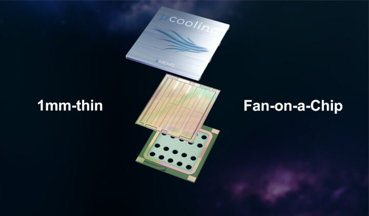
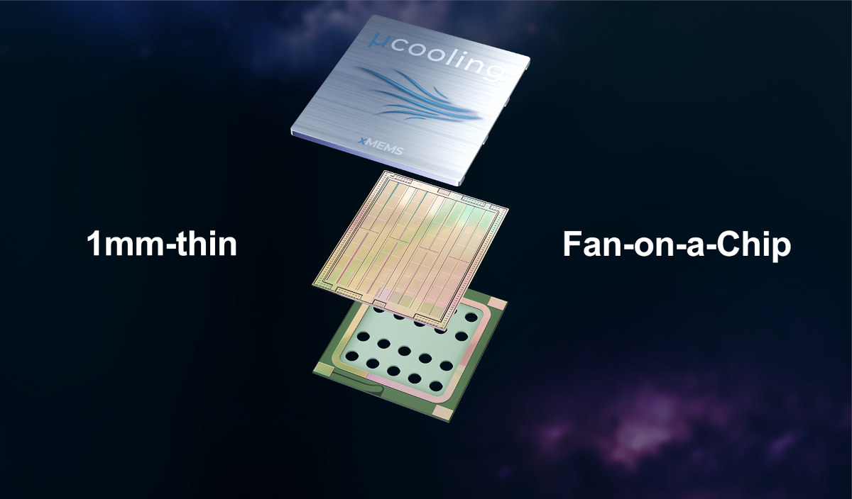


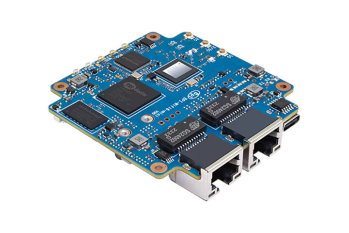


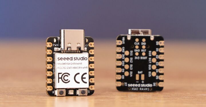


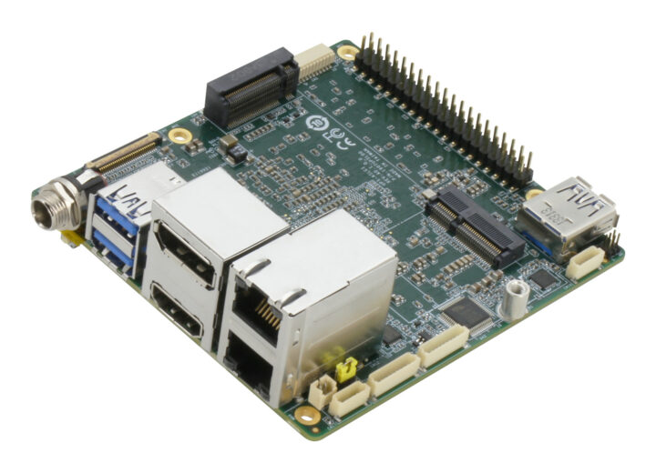


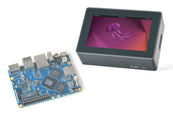


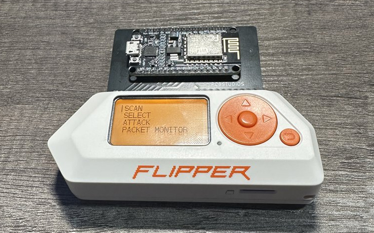


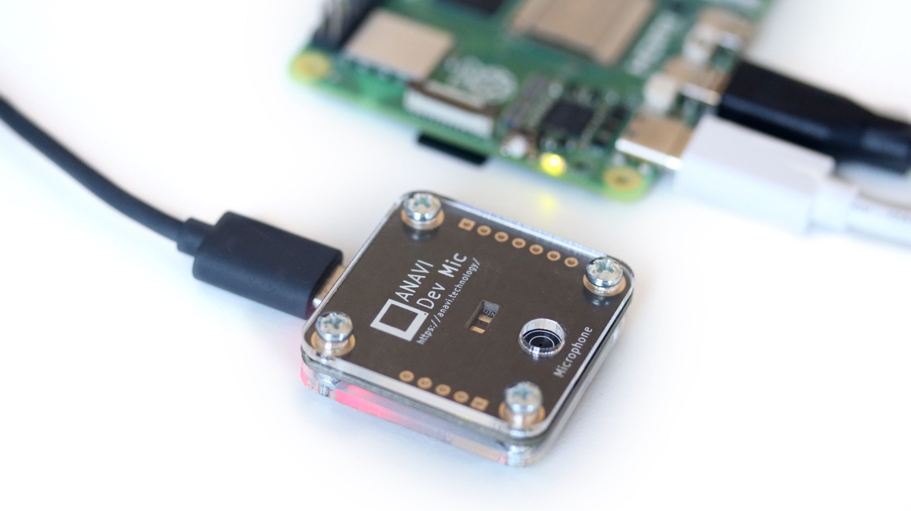


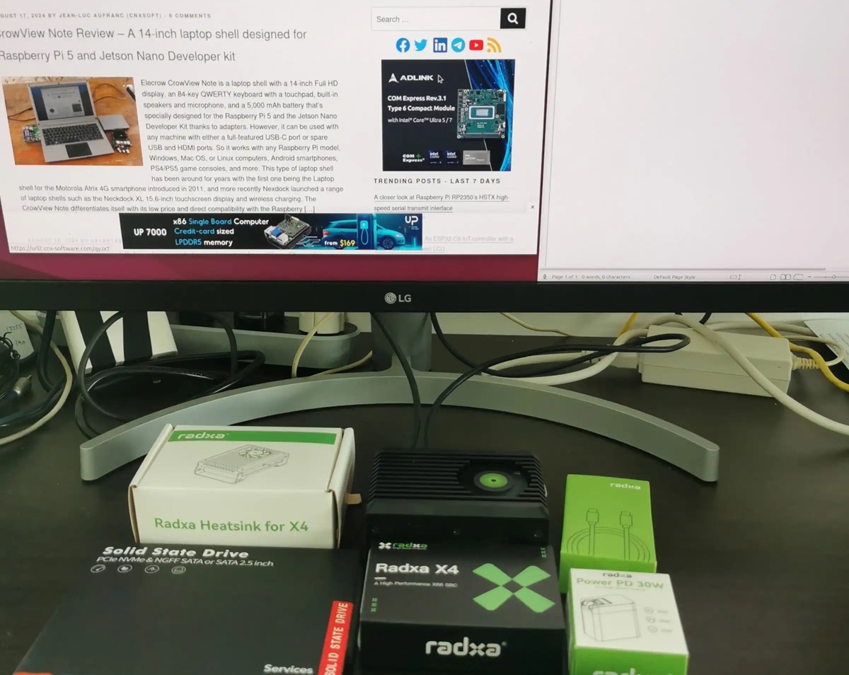


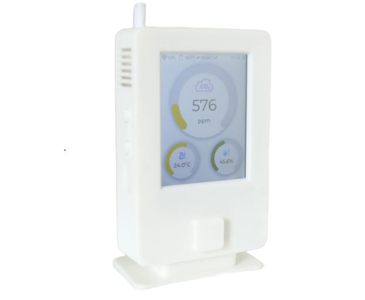


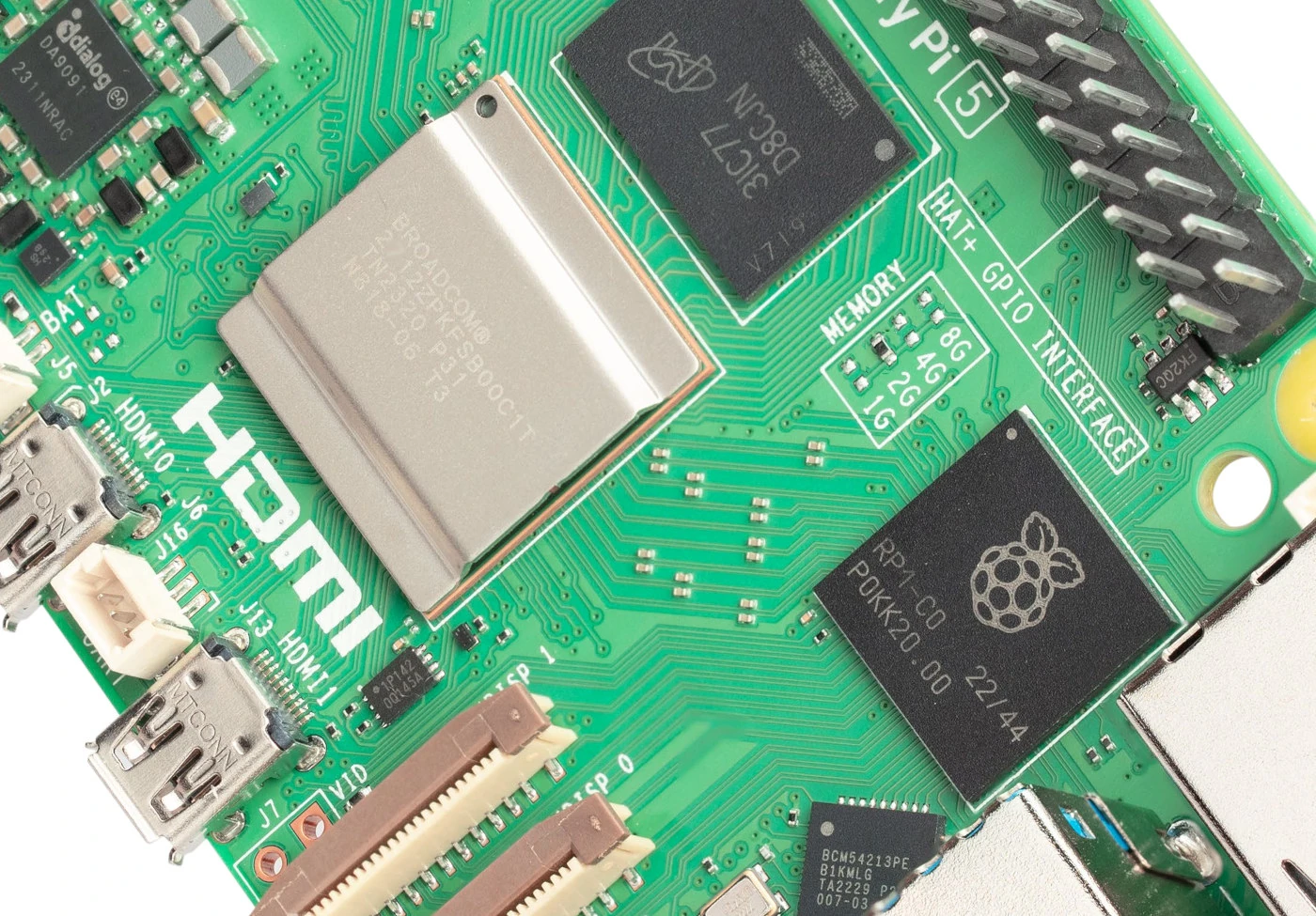


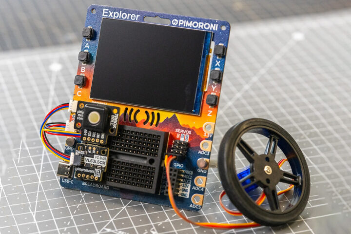


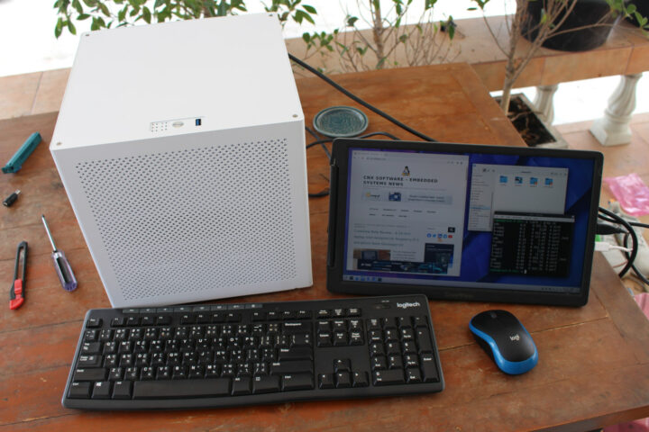
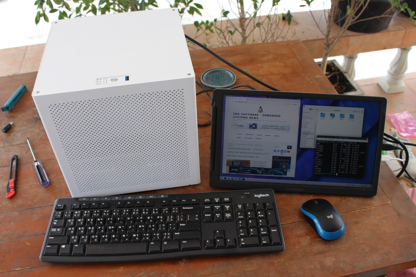


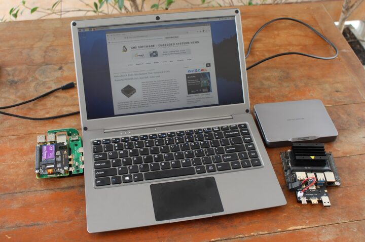


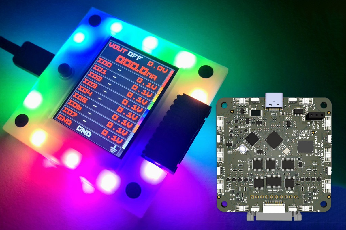


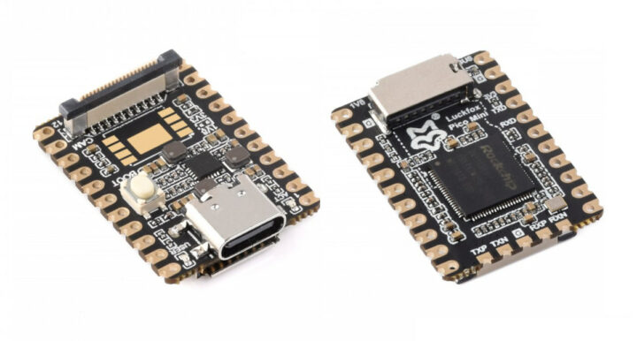


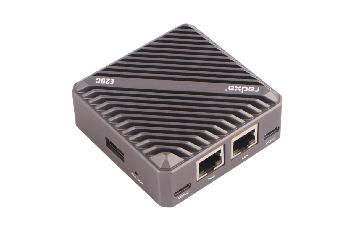


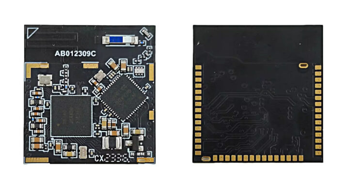
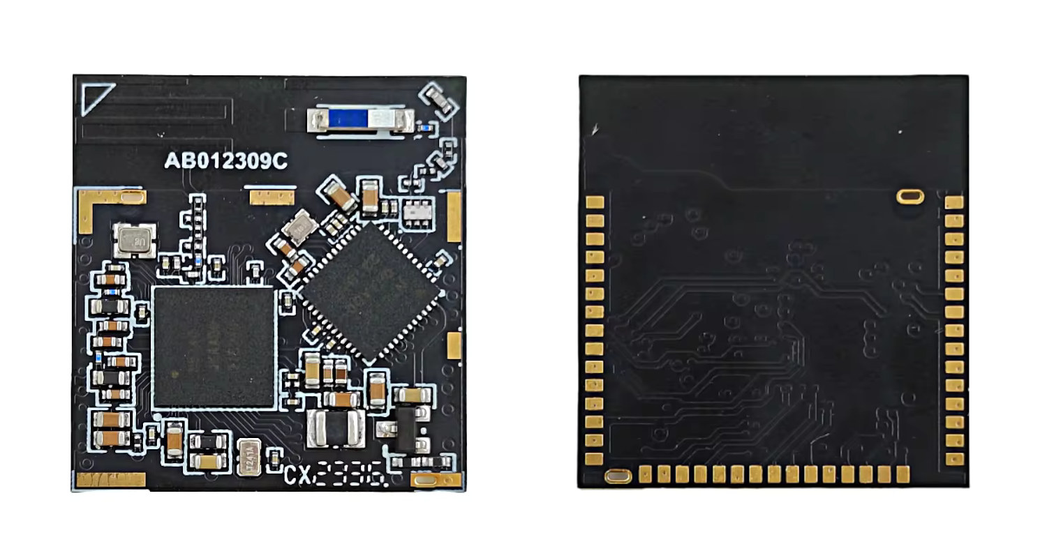


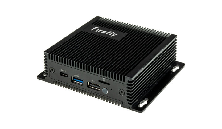


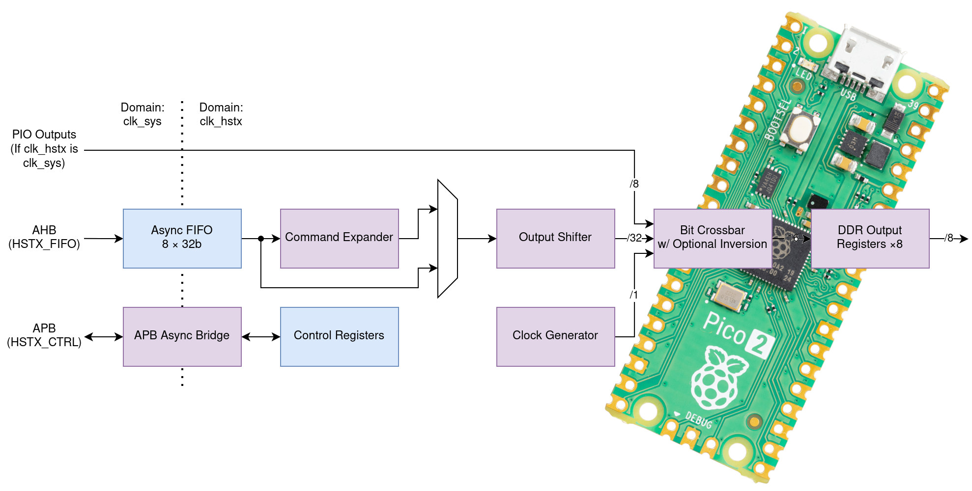


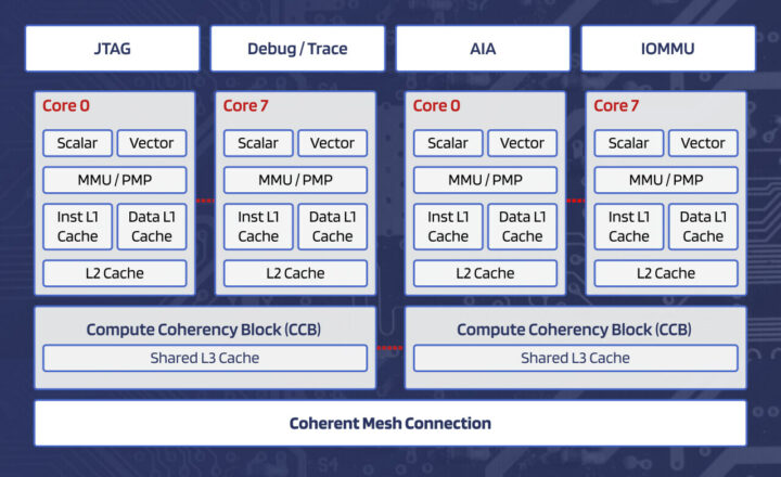
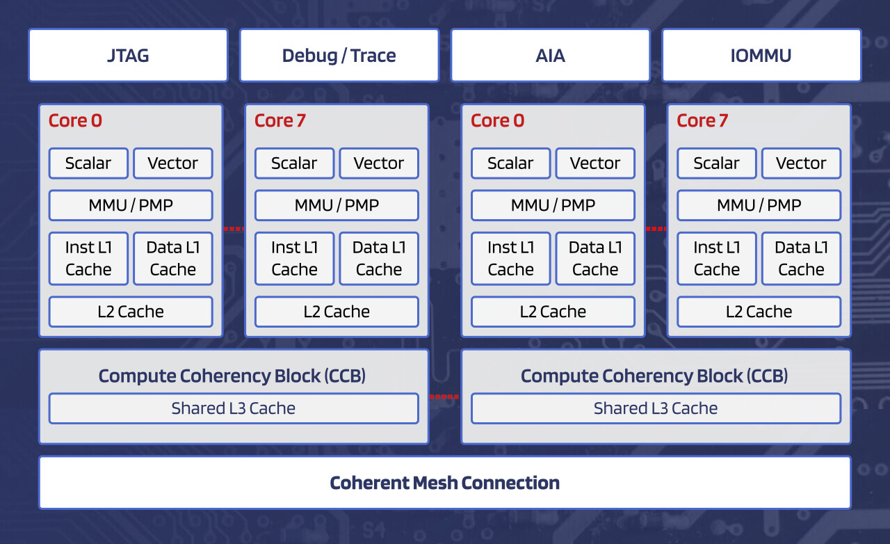


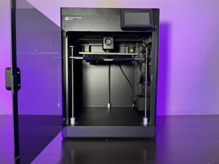
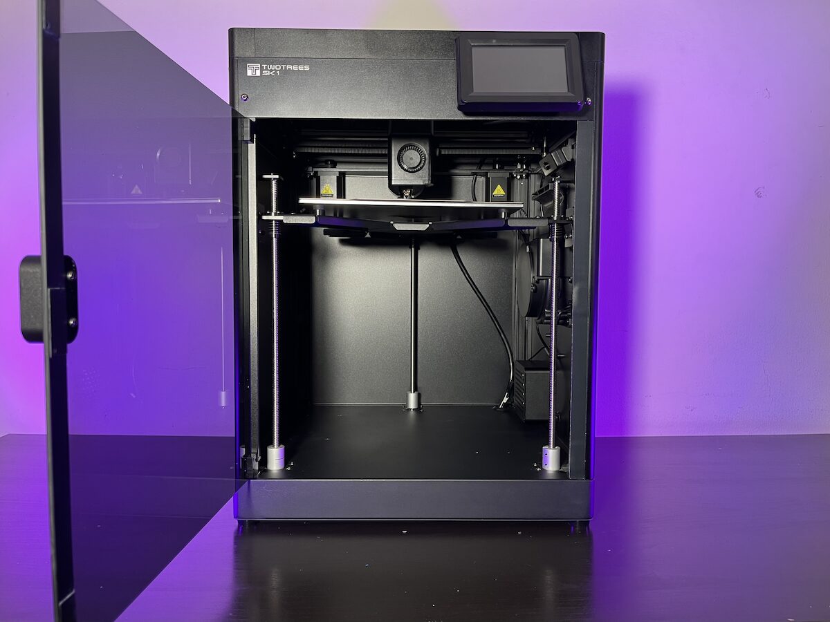


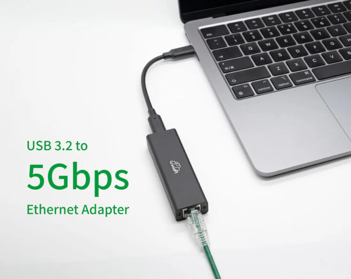


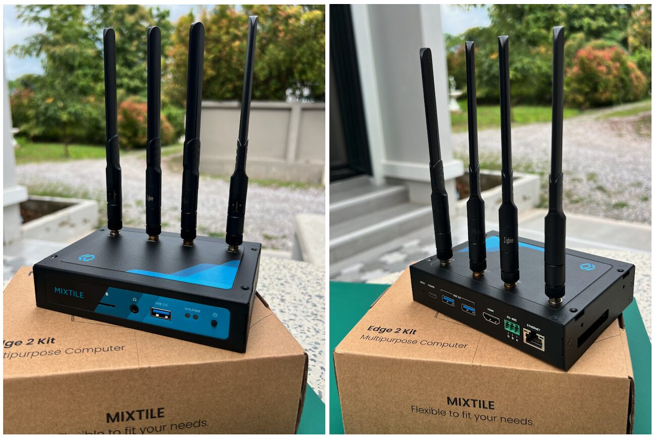


")


")
")
")
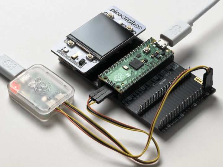
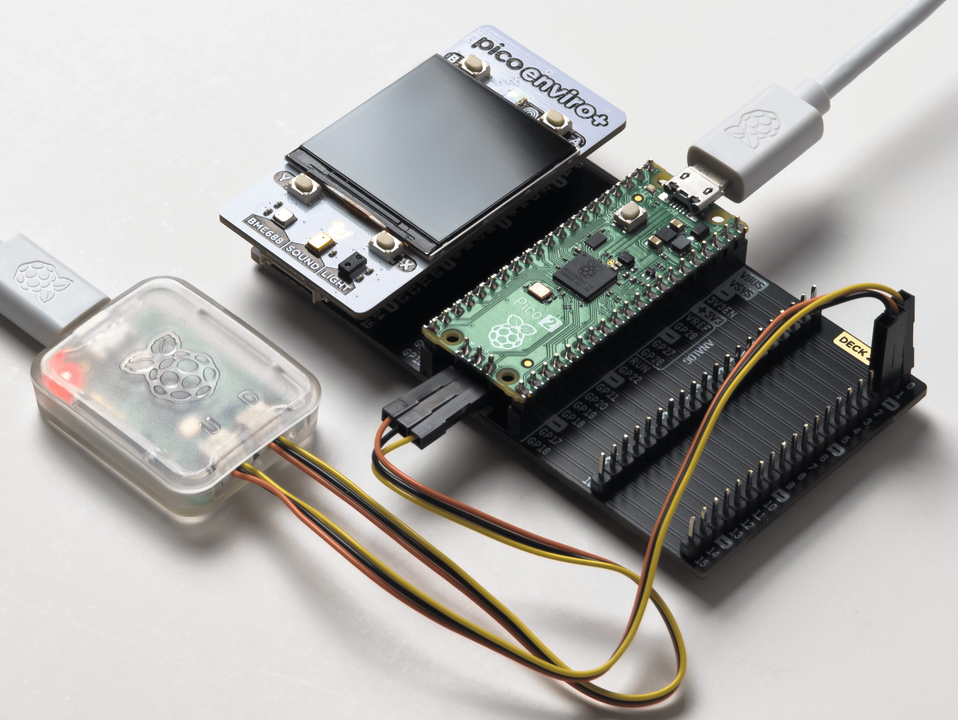


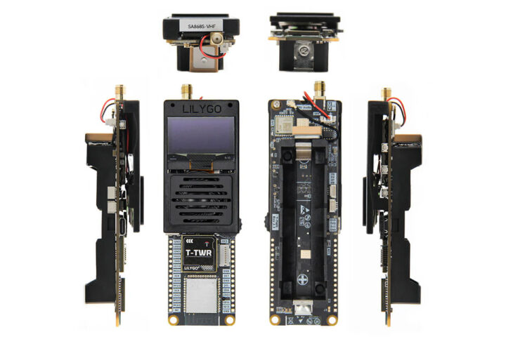
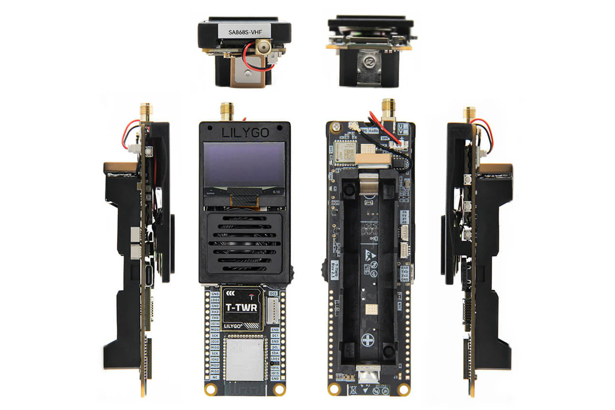


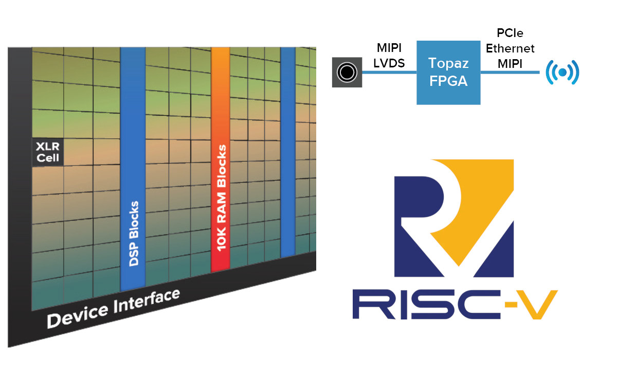


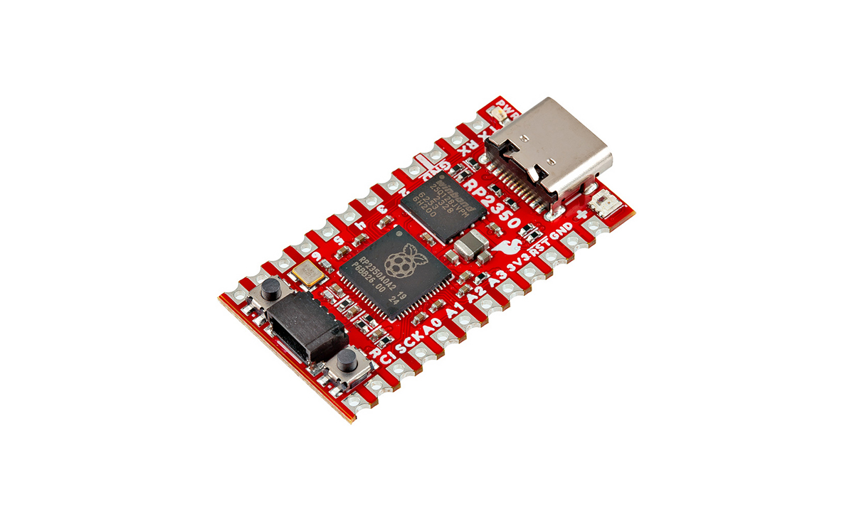


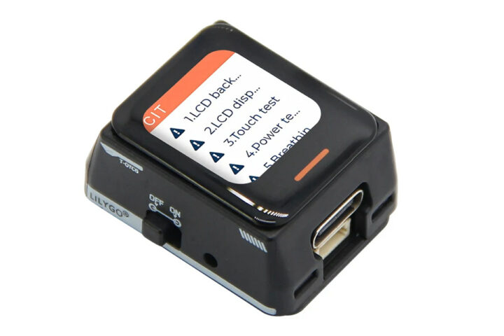
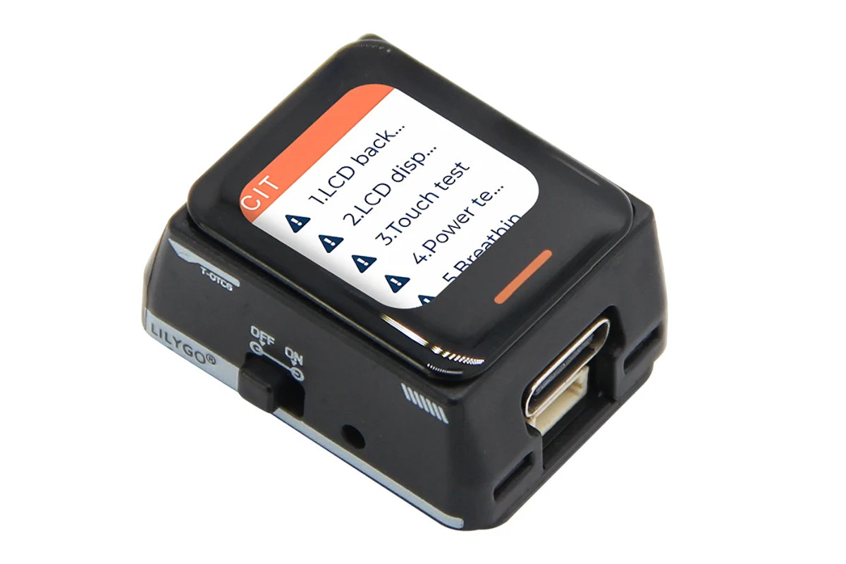


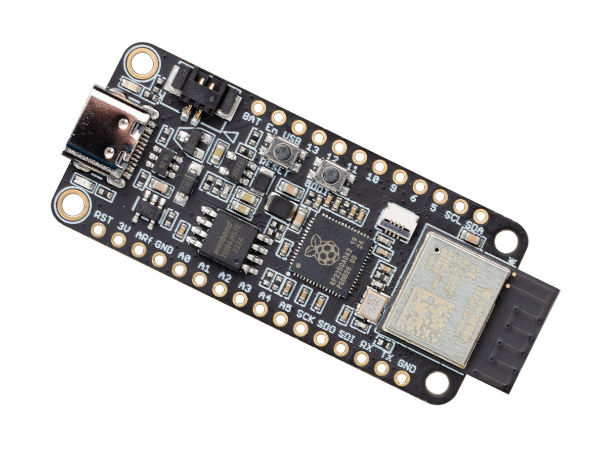

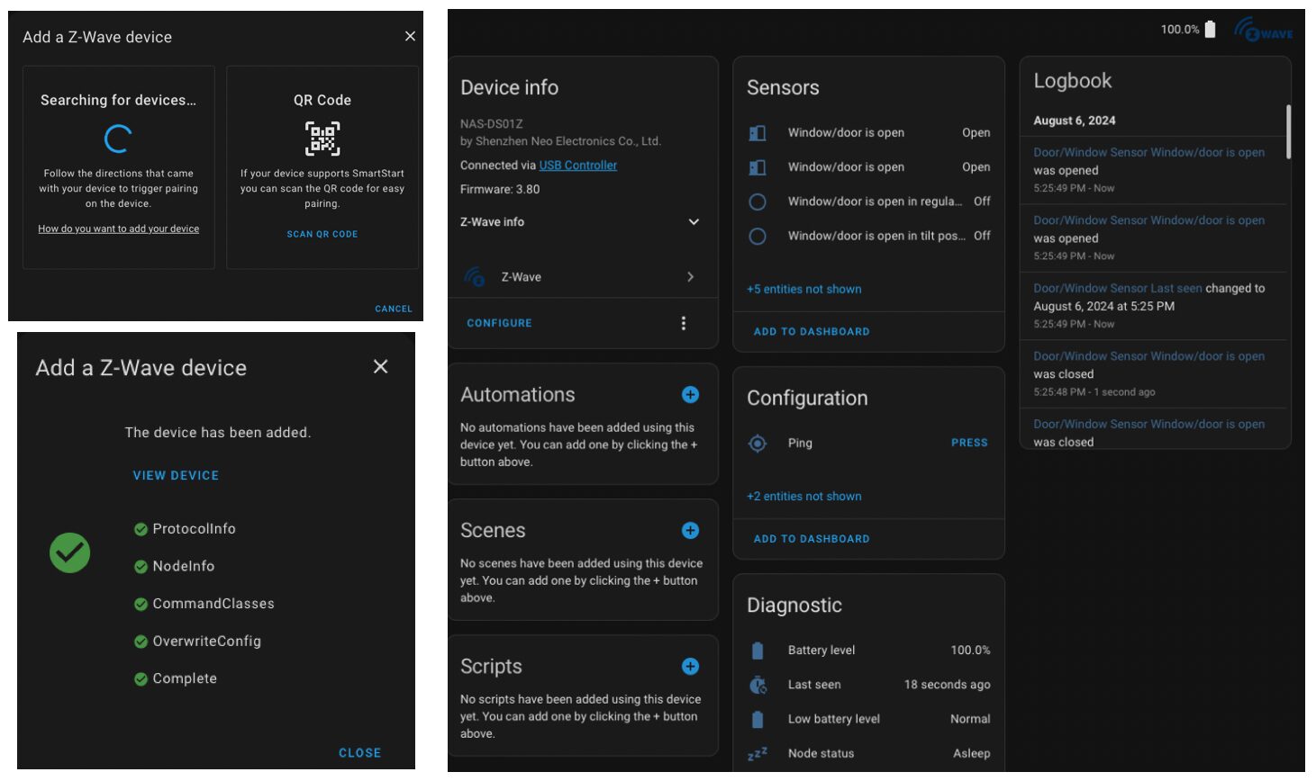