FreshRSS

Zobrazení pro čtení

Jsou dostupné nové články, klikněte pro obnovení stránky.

The Saga of AD-X2, the Battery Additive That Roiled the NBS


Senate hearings, a post office ban, the resignation of the director of the National Bureau of Standards, and his reinstatement after more than 400 scientists threatened to resign. Who knew a little box of salt could stir up such drama?

What was AD-X2?

It all started in 1947 when a bulldozer operator with a 6th grade education, Jess M. Ritchie, teamed up with UC Berkeley chemistry professor Merle Randall to promote AD-X2, an additive to extend the life of lead-acid batteries. The problem of these rechargeable batteries’ dwindling capacity was well known. If AD-X2 worked as advertised, millions of car owners would save money.

Black and white photo of a man in a suit holding an object in his hands and talking. Jess M. Ritchie demonstrates his AD-X2 battery additive before the Senate Select Committee on Small Business.National Institute of Standards and Technology Digital Collections

A basic lead-acid battery has two electrodes, one of lead and the other of lead dioxide, immersed in dilute sulfuric acid. When power is drawn from the battery, the chemical reaction splits the acid molecules, and lead sulfate is deposited in the solution. When the battery is charged, the chemical process reverses, returning the electrodes to their original state—almost. Each time the cell is discharged, the lead sulfate “hardens” and less of it can dissolve in the sulfuric acid. Over time, it flakes off, and the battery loses capacity until it’s dead.

By the 1930s, so many companies had come up with battery additives that the U.S. National Bureau of Standards stepped in. Its lab tests revealed that most were variations of salt mixtures, such as sodium and magnesium sulfates. Although the additives might help the battery charge faster, they didn’t extend battery life. In May 1931, NBS (now the National Institute of Standards and Technology, or NIST) summarized its findings in Letter Circular No. 302: “No case has been found in which this fundamental reaction is materially altered by the use of these battery compounds and solutions.”

Of course, innovation never stops. Entrepreneurs kept bringing new battery additives to market, and the NBS kept testing them and finding them ineffective.

Do battery additives work?

After World War II, the National Better Business Bureau decided to update its own publication on battery additives, “Battery Compounds and Solutions.” The publication included a March 1949 letter from NBS director Edward Condon, reiterating the NBS position on additives. Prior to heading NBS, Condon, a physicist, had been associate director of research at Westinghouse Electric in Pittsburgh and a consultant to the National Defense Research Committee. He helped set up MIT’s Radiation Laboratory, and he was also briefly part of the Manhattan Project. Needless to say, Condon was familiar with standard practices for research and testing.

Meanwhile, Ritchie claimed that AD-X2’s secret formula set it apart from the hundreds of other additives on the market. He convinced his senator, William Knowland, a Republican from Oakland, Calif., to write to NBS and request that AD-X2 be tested. NBS declined, not out of any prejudice or ill will, but because it tested products only at the request of other government agencies. The bureau also had a longstanding policy of not naming the brands it tested and not allowing its findings to be used in advertisements.

Photo of a product box with directions printed on it. AD-X2 consisted mainly of Epsom salt and Glauber’s salt.National Institute of Standards and Technology Digital Collections

Ritchie cried foul, claiming that NBS was keeping new businesses from entering the marketplace. Merle Randall launched an aggressive correspondence with Condon and George W. Vinal, chief of NBS’s electrochemistry section, extolling AD-X2 and the testimonials of many users. In its responses, NBS patiently pointed out the difference between anecdotal evidence and rigorous lab testing.

Enter the Federal Trade Commission. The FTC had received a complaint from the National Better Business Bureau, which suspected that Pioneers, Inc.—Randall and Ritchie’s distribution company—was making false advertising claims. On 22 March 1950, the FTC formally asked NBS to test AD-X2.

By then, NBS had already extensively tested the additive. A chemical analysis revealed that it was 46.6 percent magnesium sulfate (Epsom salt) and 49.2 percent sodium sulfate (Glauber’s salt, a horse laxative) with the remainder being water of hydration (water that’s been chemically treated to form a hydrate). That is, AD-X2 was similar in composition to every other additive on the market. But, because of its policy of not disclosing which brands it tests, NBS didn’t immediately announce what it had learned.

The David and Goliath of battery additives

NBS then did something unusual: It agreed to ignore its own policy and let the National Better Business Bureau include the results of its AD-X2 tests in a public statement, which was published in August 1950. The NBBB allowed Pioneers to include a dissenting comment: “These tests were not run in accordance with our specification and therefore did not indicate the value to be derived from our product.”

Far from being cowed by the NBBB’s statement, Ritchie was energized, and his story was taken up by the mainstream media. Newsweek’s coverage pitted an up-from-your-bootstraps David against an overreaching governmental Goliath. Trade publications, such as Western Construction News and Batteryman, also published flattering stories about Pioneers. AD-X2 sales soared.

Then, in January 1951, NBS released its updated pamphlet on battery additives, Circular 504. Once again, tests by the NBS found no difference in performance between batteries treated with additives and the untreated control group. The Government Printing Office sold the circular for 15 cents, and it was one of NBS’s most popular publications. AD-X2 sales plummeted.

Ritchie needed a new arena in which to challenge NBS. He turned to politics. He called on all of his distributors to write to their senators. Between July and December 1951, 28 U.S. senators and one U.S. representative wrote to NBS on behalf of Pioneers.

Condon was losing his ability to effectively represent the Bureau. Although the Senate had confirmed Condon’s nomination as director without opposition in 1945, he was under investigation by the House Committee on Un-American Activities for several years. FBI Director J. Edgar Hoover suspected Condon to be a Soviet spy. (To be fair, Hoover suspected the same of many people.) Condon was repeatedly cleared and had the public backing of many prominent scientists.

But Condon felt the investigations were becoming too much of a distraction, and so he resigned on 10 August 1951. Allen V. Astin became acting director, and then permanent director the following year. And he inherited the AD-X2 mess.

Astin had been with NBS since 1930. Originally working in the electronics division, he developed radio telemetry techniques, and he designed instruments to study dielectric materials and measurements. During World War II, he shifted to military R&D, most notably development of the proximity fuse, which detonates an explosive device as it approaches a target. I don’t think that work prepared him for the political bombs that Ritchie and his supporters kept lobbing at him.

Mr. Ritchie almost goes to Washington

On 6 September 1951, another government agency entered the fray. C.C. Garner, chief inspector of the U.S. Post Office Department, wrote to Astin requesting yet another test of AD-X2. NBS dutifully submitted a report that the additive had “no beneficial effects on the performance of lead acid batteries.” The post office then charged Pioneers with mail fraud, and Ritchie was ordered to appear at a hearing in Washington, D.C., on 6 April 1952. More tests were ordered, and the hearing was delayed for months.

Back in March 1950, Ritchie had lost his biggest champion when Merle Randall died. In preparation for the hearing, Ritchie hired another scientist: Keith J. Laidler, an assistant professor of chemistry at the Catholic University of America. Laidler wrote a critique of Circular 504, questioning NBS’s objectivity and testing protocols.

Ritchie also got Harold Weber, a professor of chemical engineering at MIT, to agree to test AD-X2 and to work as an unpaid consultant to the Senate Select Committee on Small Business.

Life was about to get more complicated for Astin and NBS.

Why did the NBS Director resign?

Trying to put an end to the Pioneers affair, Astin agreed in the spring of 1952 that NBS would conduct a public test of AD-X2 according to terms set by Ritchie. Once again, the bureau concluded that the battery additive had no beneficial effect.

However, NBS deviated slightly from the agreed-upon parameters for the test. Although the bureau had a good scientific reason for the minor change, Ritchie had a predictably overblown reaction—NBS cheated!

Then, on 18 December 1952, the Senate Select Committee on Small Business—for which Ritchie’s ally Harold Weber was consulting—issued a press release summarizing the results from the MIT tests: AD-X2 worked! The results “demonstrate beyond a reasonable doubt that this material is in fact valuable, and give complete support to the claims of the manufacturer.” NBS was “simply psychologically incapable of giving Battery AD-X2 a fair trial.”

Black and white photo of a man standing next to a row of lead-acid batteries. The National Bureau of Standards’ regular tests of battery additives found that the products did not work as claimed.National Institute of Standards and Technology Digital Collections

But the press release distorted the MIT results.The MIT tests had focused on diluted solutions and slow charging rates, not the normal use conditions for automobiles, and even then AD-X2’s impact was marginal. Once NBS scientists got their hands on the report, they identified the flaws in the testing.

How did the AD-X2 controversy end?

The post office finally got around to holding its mail fraud hearing in the fall of 1952. Ritchie failed to attend in person and didn’t realize his reports would not be read into the record without him, which meant the hearing was decidedly one-sided in favor of NBS. On 27 February 1953, the Post Office Department issued a mail fraud alert. All of Pioneers’ mail would be stopped and returned to sender stamped “fraudulent.” If this charge stuck, Ritchie’s business would crumble.

But something else happened during the fall of 1952: Dwight D. Eisenhower, running on a pro-business platform, was elected U.S. president in a landslide.

Ritchie found a sympathetic ear in Eisenhower’s newly appointed Secretary of Commerce Sinclair Weeks, who acted decisively. The mail fraud alert had been issued on a Friday. Over the weekend, Weeks had a letter hand-delivered to Postmaster General Arthur Summerfield, another Eisenhower appointee. By Monday, the fraud alert had been suspended.

What’s more, Weeks found that Astin was “not sufficiently objective” and lacked a “business point of view,” and so he asked for Astin’s resignation on 24 March 1953. Astin complied. Perhaps Weeks thought this would be a mundane dismissal, just one of the thousands of political appointments that change hands with every new administration. That was not the case.

More than 400 NBS scientists—over 10 percent of the bureau’s technical staff— threatened to resign in protest. The American Academy for the Advancement of Science also backed Astin and NBS. In an editorial published in Science, the AAAS called the battery additive controversy itself “minor.” “The important issue is the fact that the independence of the scientist in his findings has been challenged, that a gross injustice has been done, and that scientific work in the government has been placed in jeopardy,” the editorial stated.

Two black and white portrait photos of men in suits. National Bureau of Standards director Edward Condon [left] resigned in 1951 because investigations into his political beliefs were impeding his ability to represent the bureau. Incoming director Allen V. Astin [right] inherited the AD-X2 controversy, which eventually led to Astin’s dismissal and then his reinstatement after a large-scale protest by NBS researchers and others. National Institute of Standards and Technology Digital Collections

Clearly, AD-X2’s effectiveness was no longer the central issue. The controversy was a stand-in for a larger debate concerning the role of government in supporting small business, the use of science in making policy decisions, and the independence of researchers. Over the previous few years, highly respected scientists, including Edward Condon and J. Robert Oppenheimer, had been repeatedly investigated for their political beliefs. The request for Astin’s resignation was yet another government incursion into scientific freedom.

Weeks, realizing his mistake, temporarily reinstated Astin on 17 April 1953, the day the resignation was supposed to take effect. He also asked the National Academy of Sciences to test AD-X2 in both the lab and the field. By the time the academy’s report came out in October 1953, Weeks had permanently reinstated Astin. The report, unsurprisingly, concluded that NBS was correct: AD-X2 had no merit. Science had won.

NIST makes a movie

On 9 December 2023, NIST released the 20-minute docudrama The AD-X2 Controversy. The film won the Best True Story Narrative and Best of Festival at the 2023 NewsFest Film Festival. I recommend taking the time to watch it.

The AD-X2 Controversy www.youtube.com

Many of the actors are NIST staff and scientists, and they really get into their roles. Much of the dialogue comes verbatim from primary sources, including congressional hearings and contemporary newspaper accounts.

Despite being an in-house production, NIST’s film has a Hollywood connection. The film features brief interviews with actors John and Sean Astin (of Lord of The Rings and Stranger Things fame)—NBS director Astin’s son and grandson.

The AD-X2 controversy is just as relevant today as it was 70 years ago. Scientific research, business interests, and politics remain deeply entangled. If the public is to have faith in science, it must have faith in the integrity of scientists and the scientific method. I have no objection to science being challenged—that’s how science moves forward—but we have to make sure that neither profit nor politics is tipping the scales.

Part of a continuing series looking at historical artifacts that embrace the boundless potential of technology.

An abridged version of this article appears in the August 2024 print issue as “The AD-X2 Affair.”

References


I first heard about AD-X2 after my IEEE Spectrum editor sent me a notice about NIST’s short docudrama The AD-X2 Controversy, which you can, and should, stream online. NIST held a colloquium on 31 July 2018 with John Astin and his brother Alexander (Sandy), where they recalled what it was like to be college students when their father’s reputation was on the line. The agency has also compiled a wonderful list of resources, including many of the primary source government documents.

The AD-X2 controversy played out in the popular media, and I read dozens of articles following the almost daily twists and turns in the case in the New York Times, Washington Post, and Science.

I found Elio Passaglia’s A Unique Institution: The National Bureau of Standards 1950-1969 to be particularly helpful. The AD-X2 controversy is covered in detail in Chapter 2: Testing Can Be Troublesome.

A number of graduate theses have been written about AD-X2. One I consulted was Samuel Lawrence’s 1958 thesis “The Battery AD-X2 Controversy: A Study of Federal Regulation of Deceptive Business Practices.” Lawrence also published the 1962 book The Battery Additive Controversy.


Lord Kelvin and His Analog Computer


In 1870, William Thomson, mourning the death of his wife and flush with cash from various patents related to the laying of the first transatlantic telegraph cable, decided to buy a yacht. His schooner, the Lalla Rookh, became Thomson’s summer home and his base for hosting scientific parties. It also gave him firsthand experience with the challenge of accurately predicting tides.

Mariners have always been mindful of the tides lest they find themselves beached on low-lying shoals. Naval admirals guarded tide charts as top-secret information. Civilizations recognized a relationship between the tides and the moon early on, but it wasn’t until 1687 that Isaac Newton explained how the gravitational forces of the sun and the moon caused them. Nine decades later, the French astronomer and mathematician Pierre-Simon Laplace suggested that the tides could be represented as harmonic oscillations. And a century after that, Thomson used that concept to design the first machine for predicting them.

Lord Kelvin’s Rising Tide

William Thomson was born on 26 June 1824, which means this month marks his 200th birthday and a perfect time to reflect on his all-around genius. Thomson was a mathematician, physicist, engineer, and professor of natural philosophy. Queen Victoria knighted him in 1866 for his work on the transatlantic cable, then elevated him to the rank of baron in 1892 for his contributions to thermodynamics, and so he is often remembered as Lord Kelvin. He determined the correct value of absolute zero, for which he is honored by the SI unit of temperature—the kelvin. He dabbled in atmospheric electricity, was a proponent of the vortex theory of the atom, and in the absence of any knowledge of radioactivity made a rather poor estimation of the age of the Earth, which he gave as somewhere between 24 million and 400 million years.

Old photo of an elderly man with a white beard, holding a model of a molecule. William Thomson, also known as Lord Kelvin, is best known for establishing the value of absolute zero. He believed in the practical application of scientific knowledge and invented a wide array of useful, and beautiful, devices. Pictorial Press/Alamy

Thomson’s tide-predicting machine calculated the tide pattern for a given location based on 10 cyclic constituents associated with the periodic motions of the Earth, sun, and moon. (There are actually hundreds of periodic motions associated with these objects, but modern tidal analysis uses only the 37 of them that have the most significant effects.) The most notable one is the lunar semidiurnal, observable in areas that have two high tides and two low tides each day, due to the effects of the moon. The period of a lunar semidiurnal is 12 hours and 25 minutes—half of a lunar day, which lasts 24 hours and 50 minutes.

As Laplace had suggested in 1775, each tidal constituent can be represented as a repeating cosine curve, but those curves are specific to a location and can be calculated only through the collection of tidal data. Luckily for Thomson, many ports had been logging tides for decades. For places that did not have complete logs, Thomson designed both an improved tide gauge and a tidal harmonic analyzer.

On Thomson’s tide-predicting machine, each of 10 components was associated with a specific tidal constituent and had its own gearing to set the amplitude. The components were geared together so that their periods were proportional to the periods of the tidal constituents. A single crank turned all of the gears simultaneously, having the effect of summing each of the cosine curves. As the user turned the crank, an ink pen traced the resulting complex curve on a moving roll of paper. The device marked each hour with a small horizontal mark, making a deeper notch each day at noon. Turning the wheel rapidly allowed the user to run a year’s worth of tide readings in about 4 hours.

Although Thomson is credited with designing the machine, in his paper “The Tide Gauge, Tidal Harmonic Analyser, and Tide Predicter” (published in Minutes of the Proceedings of the Institution of Civil Engineers), he acknowledges a number of people who helped him solve specific problems. Craftsman Alexander Légé drew up the plan for the screw gearing for the motions of the shafts and constructed the initial prototype machine and subsequent models. Edward Roberts of the Nautical Almanac Office completed the arithmetic to express the ratio of shaft speeds. Thomson’s older brother, James, a professor of civil engineering at Queen’s College Belfast, designed the disk-globe-and-cylinder integrator that was used for the tidal harmonic analyzer. Thomson’s generous acknowledgments are a reminder that the work of engineers is almost always a team effort.

Photos of two machines. On the left, a machine with a clock face and four smaller dials. On the right, a large machine with multiple metal gears mounted on a long stand. Like Thomson’s tide-prediction machine, these two devices, developed at the U.S. Coast and Geodetic Survey, also looked at tidal harmonic oscillations. William Ferrel’s machine [left] used 19 tidal constituents, while the later machine by Rollin A. Harris and E.G. Fischer [right], relied on 37 constituents. U.S. Coast and Geodetic Survey/NOAA

As with many inventions, the tide predictor was simultaneously and independently developed elsewhere and continued to be improved by others, as did the science of tide prediction. In 1874 in the United States, William Ferrel, a mathematician with the Coast and Geodetic Survey, developed a similar harmonic analysis and prediction device that used 19 harmonic constituents. George Darwin, second son of the famous naturalist, modified and improved the harmonic analysis and published several articles on tides throughout the 1880s. Oceanographer Rollin A. Harris wrote several editions of the Manual of Tides for the Coast and Geodetic Survey from 1897 to 1907, and in 1910 he developed, with E.G. Fischer, a tide-predicting machine that used 37 constituents. In the 1920s, Arthur Doodson of the Tidal Institute of the University of Liverpool, in England, and Paul Schureman of the Coast and Geodetic Survey further refined techniques for harmonic analysis and prediction that served for decades. Because of the complexity of the math involved, many of these old brass machines remained in use into the 1950s, when electronic computers finally took over the work of predicting tides.

What Else Did Lord Kelvin Invent?

As regular readers of this column know, I always feature a museum object from the history of computer or electrical engineering and then spin out a story. When I started scouring museum collections for a suitable artifact for Thomson, I was almost paralyzed by the plethora of choices.

I considered Thomson’s double-curb transmitter, which was designed for use with the 1858 transatlantic cable to speed up telegraph signals. Thomson had sailed on the HMS Agamemnon in 1857 on its failed mission to lay a transatlantic cable and was instrumental to the team that finally succeeded.

Photo of a rectangular scientific instrument made of wood and brass. Thomson invented the double-curb transmitter to speed up signals in transatlantic cables.Science Museum Group

I also thought about featuring one of his quadrant electrometers, which measured electrical charge. Indeed, Thomson introduced a number of instruments for measuring electricity, and a good part of his legacy is his work on the precise specifications of electrical units.

But I chose to highlight Thomson’s tide-predicting machine for a number of reasons: Thomson had a lifelong love of seafaring and made many contributions to marine technology that are sometimes overshadowed by his other work. And the tide-predicting machine is an example of an early analog computer that was much more useful than Babbage’s difference engine but not nearly as well known. Also, it is simply a beautiful machine. In fact, Thomson seems to have had a knack for designing stunningly gorgeous devices. (The tide-predicting machine at top and many other Kelvin inventions are in the collection of the Science Museum, in London.)

Photo of a brass scientific instrument with a triangular base supporting a 6-sided cylinder. Thomson devised the quadrant electrometer to measure electric charge. Science Museum Group
The tide-predicting machine was not Thomson’s only contribution to maritime technology. He also patented a compass, an astronomical clock, a sounding machine, and a binnacle (a pedestal that houses nautical instruments). With respect to maritime science, Thomson thought and wrote much about the nature of waves. He mathematically explained the v-shaped wake patterns that ships and waterfowl make as they move across a body of water, which is aptly named the Kelvin wake pattern. He also described what is now known as a Kelvin wave, a type of wave that retains its shape as it moves along the shore due to the balancing of the Earth’s spin against a topographic boundary, such as a coastline.

Considering how much Thomson contributed to all things seafaring, it is amazing that these are some of his lesser known achievements. I guess if you have an insatiable curiosity, a robust grasp of mathematics and physics, and a strong desire to tinker with machinery and apply your scientific knowledge to solving practical problems that benefit humankind, you too have the means to come to great conclusions about the natural world. It can’t hurt to have a nice yacht to spend your summers on.

Part of a continuing series looking at historical artifacts that embrace the boundless potential of technology.

An abridged version of this article appears in the June 2024 print issue as “Brass for Brains.”

References


Before the days of online databases for their collections, museums would periodically publish catalogs of their collections. In 1877, the South Kensington Museum (originator of the collections of the Science Museum, in London, and now known as the Victoria & Albert Museum) published the third edition of its Catalogue of the Special Loan Collection of Scientific Apparatus, which lists a description of Lord Kelvin’s tide-predicting machine on page 11. That description is much more detailed, albeit more confusing, than its current online one.

In 1881, William Thomson published “The Tide Gauge, Tidal Harmonic Analyser, and Tide Predicter” in the Minutes of the Proceedings of the Institute of Civil Engineers, where he gave detailed information on each of those three devices.

I also relied on a number of publications from the National Oceanic and Atmospheric Administration to help me understand tidal analysis and prediction.

A Brief History of the World’s First Planetarium


In 1912, Oskar von Miller, an electrical engineer and founder of the Deutsches Museum, had an idea: Could you project an artificial starry sky onto a dome, as a way of demonstrating astronomical principles to the public?

It was such a novel concept that when von Miller approached the Carl Zeiss company in Jena, Germany, to manufacture such a projector, they initially rebuffed him. Eventually, they agreed, and under the guidance of lead engineer Walther Bauersfeld, Zeiss created something amazing.

The use of models to show the movements of the planets and stars goes back centuries, starting with mechanical orreries that used clockwork mechanisms to depict our solar system. A modern upgrade was Clair Omar Musser’s desktop electric orrery, which he designed for the Seattle World’s Fair in 1962.

The projector that Zeiss planned for the Deutsches Museum would be far more elaborate. For starters, there would be two planetariums. One would showcase the Copernican, or heliocentric, sky, displaying the stars and planets as they revolved around the sun. The other would show the Ptolemaic, or geocentric, sky, with the viewer fully immersed in the view, as if standing on the surface of the Earth, seemingly at the center of the universe.

The task of realizing those ideas fell to Bauersfeld, a mechanical engineer by training and a managing director at Zeiss.

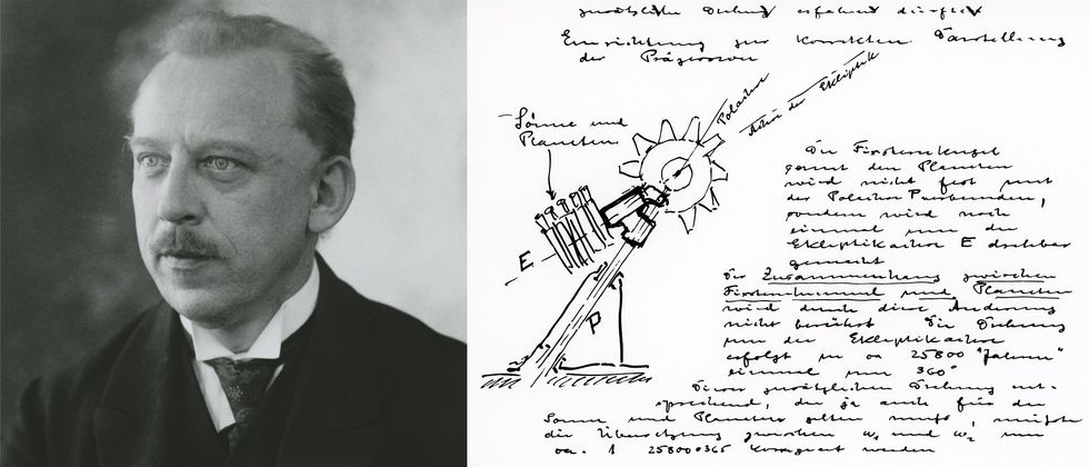
On the left, a 1927 black and white photo of a man wearing a suit and tie. On the right, a rough sketch of an apparatus with handwritten notes. Zeiss engineer Walther Bauersfeld worked out the electromechanical details of the planetarium. In this May 1920 entry from his lab notebook [right], he sketched the two-axis system for showing the daily and annual motions of the stars.ZEISS Archive

At first, Bauersfeld focused on projecting just the sun, moon, and planets of our solar system. At the suggestion of his boss, Rudolf Straubel, he added stars. World War I interrupted the work, but by 1920 Bauersfeld was back at it. One entry in May 1920 in Bauersfeld’s meticulous lab notebook showed the earliest depiction of the two-axis design that allowed for the display of the daily as well as the annual motions of the stars. (The notebook is preserved in the Zeiss Archive.)

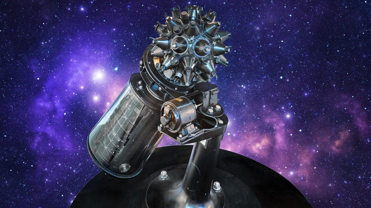
The planetarium projector was in fact a concatenation of many smaller projectors and a host of gears. According to the Zeiss Archive, a large sphere held all of the projectors for the fixed stars as well as a “planet cage” that held projectors for the sun, the moon, and the planets Mercury, Venus, Mars, Jupiter, and Saturn. The fixed-star sphere was positioned so that it projected outward from the exact center of the dome. The planetarium also had projectors for the Milky Way and the names of major constellations.

The projectors within the planet cage were organized in tiers with complex gearing that allowed a motorized drive to move them around one axis to simulate the annual rotations of these celestial objects against the backdrop of the stars. The entire projector could also rotate around a second axis, simulating the Earth’s polar axis, to show the rising and setting of the sun, moon, and planets over the horizon.

Black and white photo of a domed structure under construction with workers standing on the top. The Zeiss planetarium projected onto a spherical surface, which consisted of a geodesic steel lattice overlaid with concrete.Zeiss Archive
Bauersfeld also contributed to the design of the surrounding projection dome, which achieved its exactly spherical surface by way of a geodesic network of steel rods covered by a thin layer of concrete.

Planetariums catch on worldwide

The first demonstration of what became known as the Zeiss Model I projector took place on 21 October 1923 before the Deutsches Museum committee in their not-yet-completed building, in Munich. “This planetarium is a marvel,” von Miller declared in an administrative report.

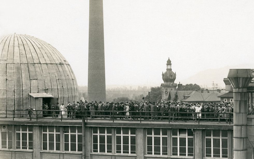
A photo of a crowd of people on the roof on a building. In 1924, public demonstrations of the Zeiss planetarium took place on the roof of the company’s factory in Jena, Germany.ZEISS Archive
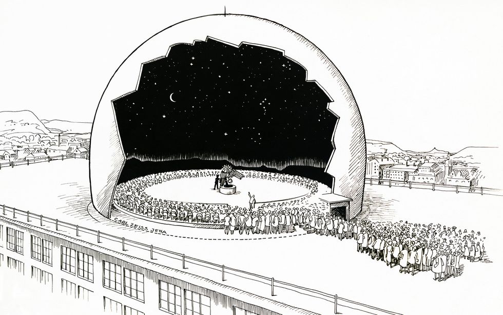
The projector then returned north to Jena for further adjustments and testing. The company also began offering demonstrations of the projector in a makeshift dome on the roof of its factory. From July to September 1924, more than 30,000 visitors experienced the Zeisshimmel (Zeiss sky) this way. These demonstrations became informal visitor-experience studies and allowed Zeiss and the museum to make refinements and improvements.

On 7 May 1925, the world’s first projection planetarium officially opened to the public at the Deutsches Museum. The Zeiss Model I displayed 4,500 stars, the band of the Milky Way, the sun, moon, Mercury, Venus, Mars, Jupiter, and Saturn. Gears and motors moved the projector to replicate the changes in the sky as Earth rotated on its axis and revolved around the sun. Visitors viewed this simulation of the night sky from the latitude of Munich and in the comfort of a climate-controlled building, although at first chairs were not provided. (I get a crick in the neck just thinking about it.) The projector was bolted to the floor, but later versions were mounted on rails to move them back and forth. A presenter operated the machine and lectured on astronomical topics, pointing out constellations and the orbits of the planets.

Illustration showing a cutaway of a planetarium dome with a crowd of people waiting to enter. Word of the Zeiss planetarium spread quickly, through postcards and images.ZEISS Archive
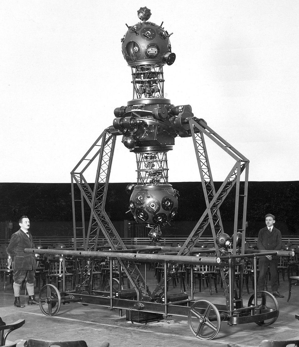
The planetarium’s influence quickly extended far beyond Germany, as museums and schools around the world incorporated the technology into immersive experiences for science education and public outreach. Each new planetarium was greeted with curiosity and excitement. Postcards and images of planetariums (both the distinctive domed buildings and the complicated machines) circulated widely.

In 1926, Zeiss opened its own planetarium in Jena based on Bauersfeld’s specifications. The first city outside of Germany to acquire a Zeiss planetarium was Vienna. It opened in a temporary structure on 7 May 1927 and in a permanent structure four years later, only to be destroyed during World War II.

The Zeiss planetarium in Rome, which opened in 1928, projected the stars onto the domed vault of the 3rd-century Aula Ottagona, part of the ancient Baths of Diocletian.

The first planetarium in the western hemisphere opened in Chicago in May 1930. Philanthropist Max Adler, a former executive at Sears, contributed funds to the building that now bears his name. He called it a “classroom under the heavens.”

Japan’s first planetarium, a Zeiss Model II, opened in Osaka in 1937 at the Osaka City Electricity Science Museum. As its name suggests, the museum showcased exhibits on electricity, funded by the municipal power company. The city council had to be convinced of the educational value of the planetarium. But the mayor and other enthusiasts supported it. The planetarium operated for 50 years.

Who doesn’t love a planetarium?

After World War II and the division of Germany, the Zeiss company also split in two, with operations continuing at Oberkochen in the west and Jena in the east. Both branches continued to develop the planetarium through the Zeiss Model VI before shifting the nomenclature to more exotic names, such as the Spacemaster, Skymaster, and Cosmorama.

A black and white photo of a large complex dumbbell-shaped apparatus mounted on a wheeled cart. The two large spheres of the Zeiss Model II, introduced in 1926, displayed the skies of the northern and southern hemispheres, respectively. Each sphere contained a number of smaller projectors.ZEISS Archive

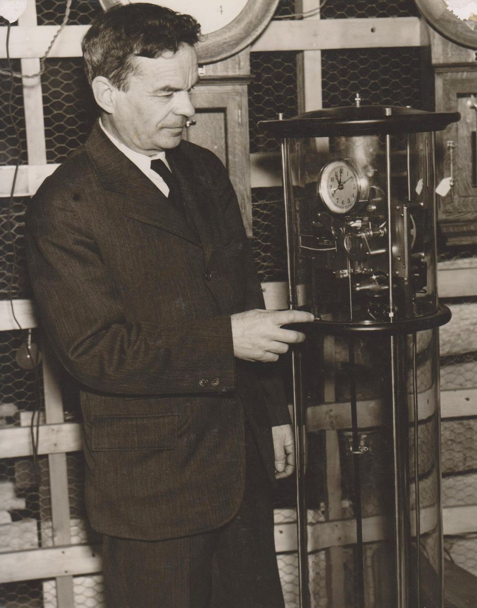
Over the years, refinements included increased precision, the addition of more stars, automatic controls that allowed the programming of complete shows, and a shift to fiber optics and LED lighting. Zeiss still produces planetariums in a variety of configurations for different size domes.

Today more than 4,000 planetariums are in operation globally. A planetarium is often the first place where children connect what they see in the night sky to a broader science and an understanding of the universe. My hometown of Richmond, Va., opened its first planetarium in April 1983 at the Science Museum of Virginia. That was a bit late in the big scheme of things, but just in time to wow me as a kid. I still remember the first show I saw, narrated by an animatronic Mark Twain with a focus on the 1986 visit of Halley’s Comet.

By then the museum also had a giant OmniMax screen that let me soar over the Grand Canyon, watch beavers transform the landscape, and swim with whale sharks, all from the comfort of my reclining seat. No wonder the museum is where I got my start as a public historian of science and technology. I began volunteering there at age 14 and have never looked back.

Part of a continuing series looking at historical artifacts that embrace the boundless potential of technology.

An abridged version of this article appears in the May 2024 print issue as “A Planetarium Is Born.”

References


In 2023, the Deutsches Museum celebrated the centennial of its planetarium, with the exhibition 100 Years of the Planetarium, which included artifacts such as astrolabes and armillary spheres as well as a star show in a specially built planetarium dome.

I am always appreciative of corporations that recognize their own history and maintain robust archives. Zeiss has a wonderful collection of historic photos online with detailed descriptions.

I also consulted The Zeiss Works and the Carl Zeiss Foundation in Jena by Felix Auerbach, although I read an English translation that was in the Robert B. Ariail Collection of Historical Astronomy, part of the University of South Carolina’s special collections.


This Clock Made Power Grids Possible


On 23 October 1916, an engineer named Henry E. Warren quietly revolutionized power transmission by installing an electric clock in the L Street generating station of Boston’s Edison Electric Illuminating Co. This master station clock kept a very particular type of time: It used a synchronous self-starting motor in conjunction with a pendulum to help maintain the station’s AC electricity at a steady 60-cycle-per-second frequency.

As more power stations adopted the clocks, the frequency regulation allowed them to share electricity and create an interconnected power grid. Until the late 1940s, station clocks from the Warren Telechron Co. regulated over 95 percent of all U.S. electricity lines. The Telechron Model Type E master station clock shown at top was used at the Tennessee Valley Authority beginning in the 1930s.

The 60-hertz standard (or 50 hertz in most of the rest of the world) is taken for granted today, but in the early days of electrification—before the invention of the master station clock—the standard was seldom standard. And Warren, who eventually solved the grid-frequency problem, was actually working on a different puzzle when he came across the answer.

How Warren’s clocks regulated grid frequency

Photo of a man in a suit looking at and pointing to a clock apparatus. Henry E. Warren poses with one of his master station clocks. Until the late 1940s, his company’s clocks regulated over 95 percent of U.S. electricity lines.Electric Time Co.
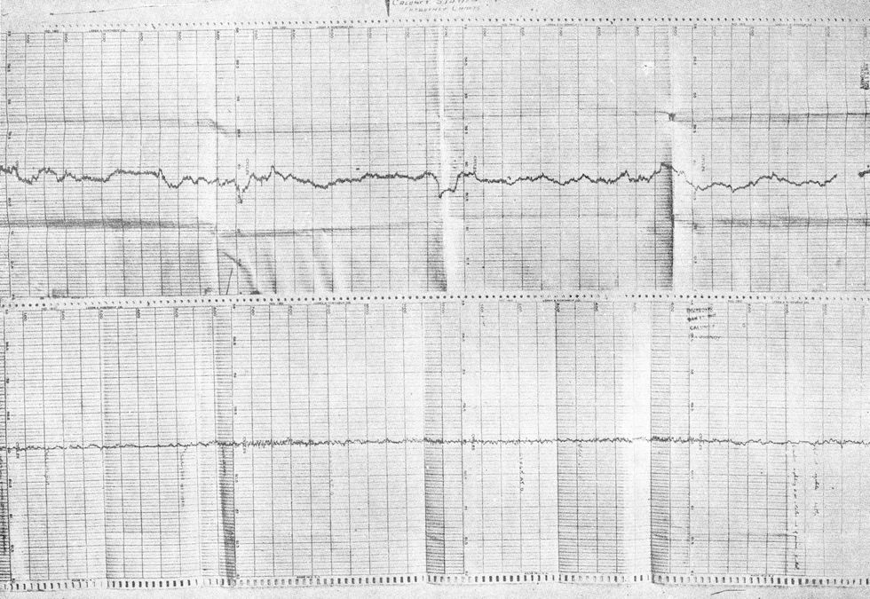
Henry Ellis Warren was born in Boston on 21 May 1872, a decade before Edison’s Pearl Street Station went online, in New York City, ushering in the dawn of the electric age. He graduated from MIT in 1894 with a degree in electrical engineering, and within the year he (along with his friend George C. Whipple, who went on to become an expert in water sanitation and to cofound the Harvard School of Public Health) had filed for their first patent: an electric thermometer intended to be used to measure temperature at a distance or in inaccessible places.

Warren went on to work in Michigan as an engineer for the Saginaw Valley Traction Co., returning to Boston in 1902 as superintendent of the Lombard Governor Co. He dabbled in real estate, set up a machine shop, continued patenting inventions, and organized the Warren Gear Works to make and sell his devices.

In 1912, Warren established the Warren Clock Co., which produced battery-operated clocks. His initial designs, as described in a series of patents, were for a pendulum clock with a permanent magnet as its bob (that’s the weight at the bottom of the pendulum). The battery would provide an electric impulse to keep the pendulum swinging, by opening and closing a circuit depending on the amplitude of the pendulum swing. Unfortunately, these early clocks were lousy timekeepers, their ability to keep time deteriorating along with the battery. Warren sought a better approach and suspected electric motors might be the answer.

In Warren’s own telling of the story, his first attempt at an electric chronometer was a crude motor that connected the gears of a clock to the Boston Edison electrical system. When he found that the clock was still losing 10 to 15 minutes a day, he called up the Edison power station—as one apparently did in 1915—and politely told them that their frequency was approximately a half cycle off. They countered that their instruments were correct, and Warren suggested the laboratory standards they used to check their meters must be in error.

The conversation could have stopped there, but Robert Hale, a research engineer, took the concern seriously and helped Warren set up an experimental demonstration at the L Street station. There, Warren designed, built, and installed the instrument he dubbed the Warren Master Station Clock. On 23 October 1916, it went into service, enabling the power transmission revolution.

Two graphs, the upper one showing a fluctuating horizontal line and the other showing a horizontal line with very little variation. These frequency measurements from Commonwealth Edison were taken before [top] and after [bottom] the installation of a Telechron master station clock. Electric Time Co.
This condensed version of events belies the fact that Warren had already been working for more than a decade on ways to regulate clocks, as well as building a reliable self-starting synchronous motor. Clocks and synchronous motors go hand in hand. In a synchronous motor, the shaft rotates at the same alternating-current frequency as the electric current; assuming the current is steady, it would be ideal for a clock. But in order to make his electric clock accurate, Warren needed an accurate and steady current, hence the master station clock.

In 1916, the Warren Clock Co. began producing the Type A master station clock, which is actually two clocks superimposed on a single clock face. The dial is divided into five 1-minute sectors and has two hands, one black and one gold. The black hand is connected to a standard mechanical pendulum clock; the gold hand is driven by a synchronous motor. Both hands circle the clock face at 60 seconds per minute. To read the clock, the operator simply had to check that the two hands were in sync; that would mean the generators were running at precisely 60 hertz.

The heyday of Warren’s electric clocks

The master station clock solved Warren’s problem of creating reliable electric clocks for use in homes and appliances. But grid operators wouldn’t have embraced it but for their coalescing desire to form an interconnected electricity grid.

That desire was nicely captured by electrical engineer Benjamin Lamme in a 1918 presentation to the Washington, D.C., section of the American Institute of Electrical Engineers (one of the founding organizations of the IEEE). In his talk, “The Technical Story of the Frequencies,” he gave the history of the previous few decades, as manufacturers and power companies debated and adapted to different frequency standards.

At the beginning, when the fledgling power industry served only a few customers, there was little need for a nationwide standard. But as electricity demand rose for both industry and residences, the need became critical. Warren’s master station clock arrived at precisely the right time. (Warren was later awarded the AIEE’s Lamme Medal for his “outstanding contributions to the development of electrical clocks and means of controlling central station frequencies.”)

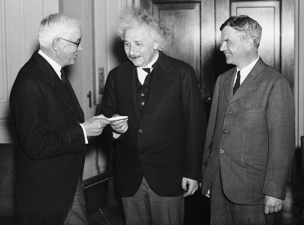
Black and white photo of three smiling men in suits. The man on the left is handing something to the man in the middle, while the man on the right looks on. In 1935, Henry Warren [right] received a medal from the Franklin Institute, in Philadelphia, for his invention of the Telechron synchronous motor. Also honored was Albert Einstein [middle], for his contributions to theoretical physics. Bettmann/Getty Images
A second reason power stations adopted the master station clock was profit. Recall that Warren was initially working on an electric clock for the home, and he had a grand vision that every household would eventually own one. More electric clocks meant more electricity usage, which meant more revenue for the power companies. In a 1937 paper that Warren read before the Clock Club in Boston, he estimated that a power company could earn US $75,000 (about $1.6 million today) if 100,000 customers each ran an electric clock 24 hours a day. Warren was thinking big for his own company and wanted to get the utilities on board.

There were several versions of the station clock. In 1920, the cheaper (and less accurate) Model B master station clock was introduced for stand-alone installations not connected to a wider electrical grid. The following year, the company unveiled the Type C clock for use in the few remaining DC power stations. According to the incredibly informative website maintained by clock enthusiast Mark Frank, the Type D existed as an internal testing device and never went into production. The final model, the Type E, came out in 1929. It functioned as a reference monitor for multiple interconnected grids.

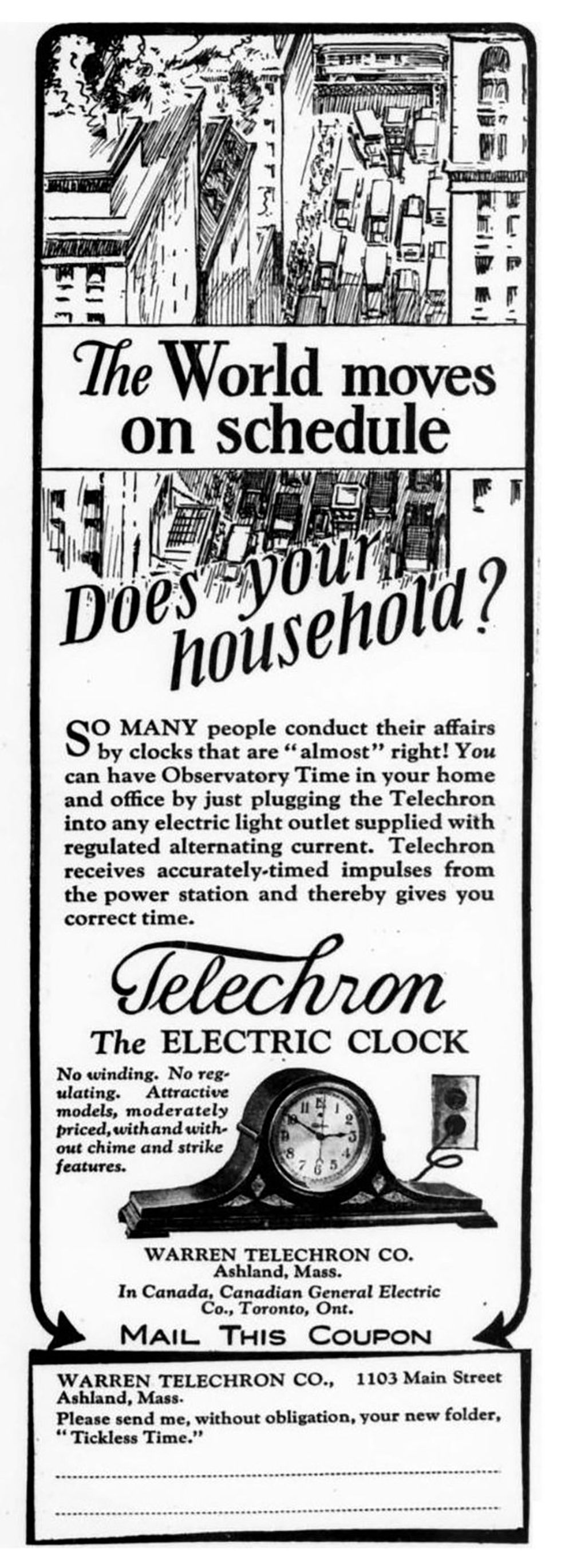
Image of an old magazine ad for an electric clock. A 1929 ad for Telechron’s electric clocks touts their use of “accurately timed impulses from the power station.” Telechron/Telechron.net
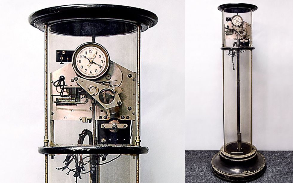
Beginning in the 1950s, improved electronics displaced electromechanical master station clocks. These days, power stations use atomic clocks to regulate grid frequency.

Back in 1917, General Electric had bought a 49 percent interest in the Warren Clock Co. Warren continued to serve as president until he retired in 1943. GE incorporated Warren’s self-starting synchronous motors into its own clocks and other instruments and licensed the motors to other companies. In 1926, the company was renamed the Warren Telechron Co. After Warren’s retirement, GE fully absorbed Telechron into its operations, eventually forming the Clock and Timer Division.

In its heyday, Telechron held a huge share of the home electric clock market—by 1926 the company had sold 20 million clocks. But by the 1950s, clocks with improved batteries and oscillating quartz crystal resonators began to replace consumer electric clocks that synchronized with the power grid. The advent of digital clocks sealed the deal. GE sold its last Telechron plant in 1979.

Today, the Telechron legacy lives on at the Electric Time Co., in Medfield, Mass., which was spun off from Telechron’s research labs in 1928. Today, Electric Time custom-manufactures tower clocks, street clocks, and building clocks. It also hosts the Electric Clock Museum, where you can make an appointment to see the Telechron Type E Master Station Clock.

Part of a continuing series looking at historical artifacts that embrace the boundless potential of technology.

An abridged version of this article appears in the March 2024 print issue as “The Clock and the Grid.”


References


Clock collectors have done a significant amount of work gathering historical source material about clocks. In particular, Mark Frank’s website, Magnificent Time Machines, was essential in explaining the different types of Warren station clocks. He even has the instruction manual for the Type E! Also consider heading to the website of the National Association of Watch and Clock Collectors for any additional questions.

It is always nice to read an inventor’s own words, and Henry Warren presented “ Utilizing the Time Characteristics of Alternating Current,” in 1919, to the Boston Section Meeting of the AIEE, explaining the self-starting synchronous motor and the station clock.

Jim Linz’s Electrifying Time: Telechron and G.E. Clocks 1925–1955 (Schiffer Publishing, 2000) is the definitive book on Warren clocks, documenting over 700 models of Telechron and GE clocks.

For understanding the entire process of electrifying the United States, and Europe, Thomas Hughes’ Networks of Power (Johns Hopkins University Press, 1983) is a classic.

What Is an Electronic Sackbut?


If you, like me, think of musical synthesizers as an artifact of 1970s rock and disco, then you, like me, will be surprised to learn that the first electronic synthesizer predates those genres by several decades

In 1945, Hugh Le Caine, a physicist at Canada’s National Research Council, began working in his spare time on a single-channel musical instrument he dubbed the Electronic Sackbut. He was intrigued by the fact that the three auditory sensations associated with music—namely, pitch, loudness, and timbre—had counterparts in electronics—namely, frequency, amplitude, and the harmonic spectrum obtained by Fourier analysis. To demonstrate those qualities, Le Caine created a synthesizer that mimicked, among other things, a brass horn known as the sackbut. It could also synthesize other horns, as well as string and reed instruments. He envisioned using the electronic sackbut in live performances, to play orchestral, big band, and experimental jazz music.

Here’s a recording of one Le Caine composition, “The Sackbut Blues”:

Short presentation of the 1948 sackbut: the sackbut blues www.youtube.com

What is a sackbut?

All of my friends who are into Renaissance music love the 2004 Coen brothers film The Ladykillers because it contains one of the few modern references to the sackbut. The original sackbut emerged in the 15th century, and it had a telescopic slide used to change pitch. It fell out of favor by the 18th century, only to be reborn as the modern-day trombone.

Le Caine chose to name his synthesizer after a thoroughly obsolete instrument to “afford the designer a certain measure of immunity from criticism.” That is, the electronic sackbut was its own invention, not an imitation of a known sound.

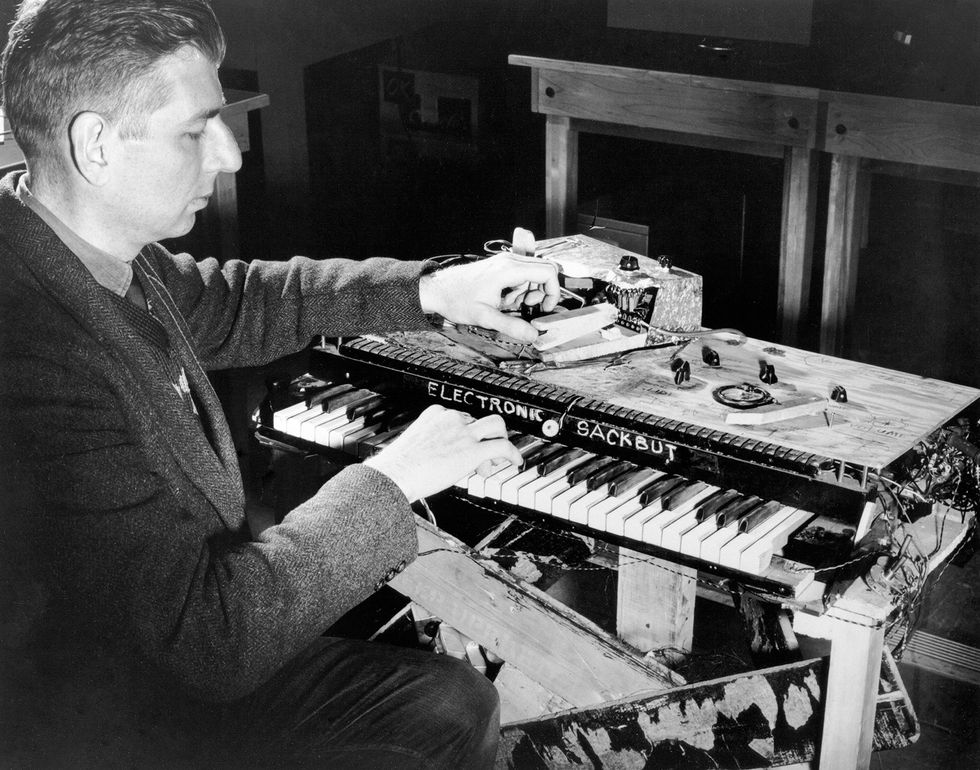
Black and white photo of a man playing a crude-looking keyboard instrument that says Electronic Sackbut. Hugh Le Caine demonstrates the left-hand control for timbre and the right-hand control for pitch and volume.National Research Council Canada Archives
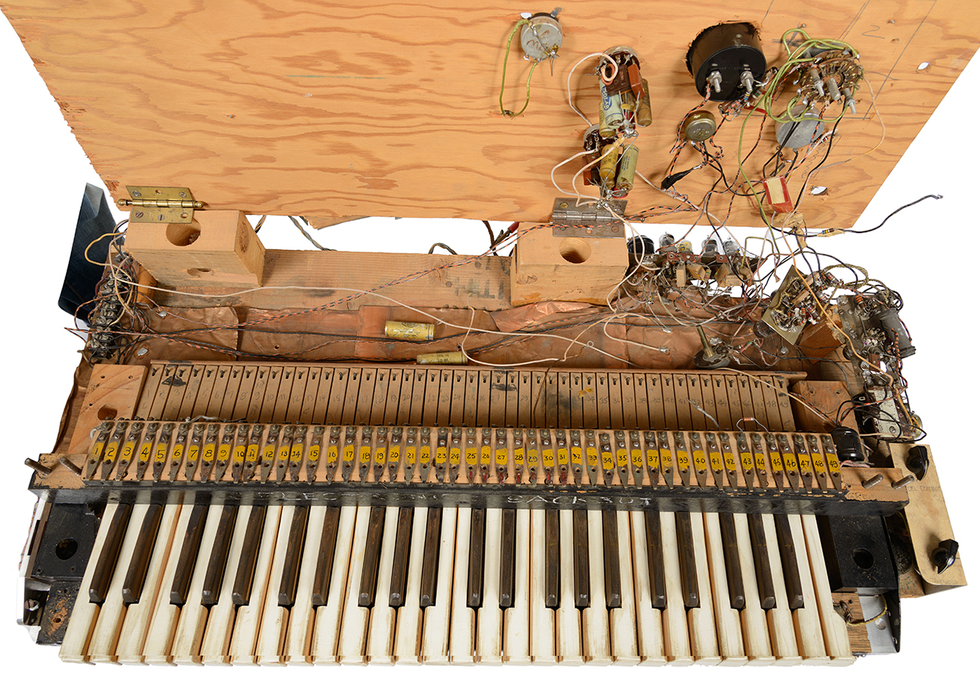
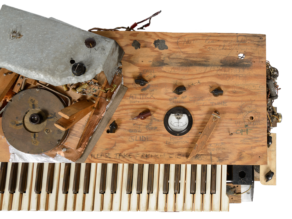
Le Caine’s first electronic sackbut [shown at top] had all of the aesthetic roughness of an experimental prototype. He built it himself with whatever was on hand, valuing functionality over appearance. He constructed the stand out of pieces of packing crates, not bothering to remove staples or bits of cloth. The boards weren’t measured and cut to fit at nice, neat right angles. The result was a haphazard contraption that looked like it could collapse at any moment. Pencil marks with the inventor’s notations and directions remain scribbled across the top.

He also winged it with the prototype’s electronics. In a 1955 letter, Le Caine admitted, “Confidentially, I have never made a complete drawing of the sackbut and have only drawn parts of it when people have asked about it.” This, of course, makes it difficult to describe the prototype’s electronics, especially considering that he kept changing them as his ideas evolved. Because it was a prototype, Le Caine would just clip wires and resolder components without always cleaning up after himself. Bill Keen, an associate of Le Caine’s at the NRC field station, described the instrument this way: “The components just hung out the side like spaghetti, and you’d just have to push them back in.”

Luckily for us, Le Caine’s biographer Gayle Young worked out much of the electronic controls and described the instrument (as well as his other musical inventions) in her 1991 book, The Sackbut Blues. The original electronic sackbut, completed in 1948, predated the invention of transistors, so it used a combination of vacuum tubes, oscillators, resistors, and the occasional device borrowed from Le Caine’s nuclear physics lab. For example, the player’s right hand controlled the volume using a pressure-sensitive keyboard mounted on springs. The movement of the springs was converted to voltage by two condensers, one at each end of the keyboard. Each key was associated with a particular note, but the pitch of the note could be tuned by rolling back and forth on the key, similar to how a violinist might produce a vibrato or glissando.

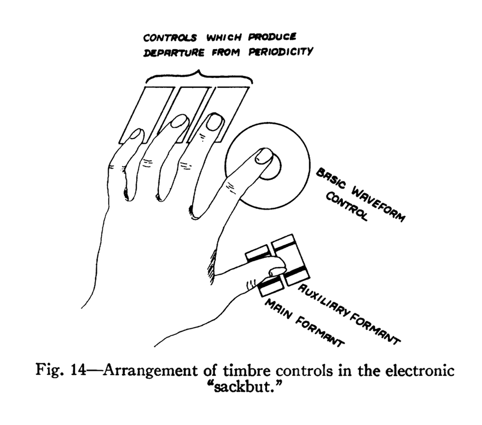
An illustration showing the positioning of a hand to control different functions. The player’s left hand was used to control the timbre of the electronic sackbut, as shown in Hugh Le Caine’s 1956 paper in Proceedings of the IRE. Proceedings of the IRE
The player’s left hand controlled the timbre with three types of frequency modulation. The thumb controlled the formant (that is, the amplitude peak in the spectrum that distinguishes the instrument’s timbre), the index finger controlled the waveform using a circular grid, and the three remaining fingers controlled the periodicity.

Throughout his life, Le Caine pursued the idea of a “beautiful sound” —something meaningful, rich, complex, and imaginative. He wanted to overcome the popular perception of electronic instruments as sounding mechanical and uninteresting. According to Young, he wanted the electronic sackbut to be as satisfying as a violin, with the same nuance and variation, but easier to learn to play. Admittedly, I have only read about how to play the electronic sackbut, but it sounds difficult to learn to manipulate in a fashion that would produce a soothing sound.

Photo of a musical keyboard attached to tangled wires and electronics mounted on plywood. The electronic sackbut used an assortment of repurposed electronics, which Le Caine tweaked as he experimented. Don Kennedy/National Music Centre
Where did the electronic sackbut originate?

I always find it interesting to consider the environment in which an invention incubates. In the case of the electronic sackbut, the instrument emerged in the shadow of the National Research Council, Canada’s federal agency for R&D in science and technology, where Le Caine worked for much of his career. How did he come to invent this extraordinary musical instrument, and how did he convince the NRC to support his work?

Le Caine had graduated from Queen’s University, in Kingston, Ont., with a master’s in physical engineering in 1939 and then joined the NRC, doing classified work on radar for the army. (Canada had a robust radar program during World War II, as I touched on in this column.)

At the conclusion of the war, Le Caine hoped to turn his attention full time to electronic music, an interest he had been toying with for at least a decade. He considered joining the acoustics lab at NRC, until he realized they were only interested in measuring the properties of sound, not in the aesthetics. He also considered joining an equipment manufacturer, such as the Hammond Organ Co., but he wanted to do fundamental research rather than commercial applications. In the end, he opted to continue working for the NRC on various nonmusical projects, including the microtron, a type of particle accelerator. But he investigated electronic music in his spare time.

Photo of a musical keyboard instrument showing hand written labels,and assorted electronics. Le Caine’s penciled notations and directions remain scribbled across the top of the electronic sackbut.Don Kennedy/National Music Centre

Beginning in 1945, Le Caine rented one of the hastily built wartime houses at the NRC field station southeast of Ottawa. He designated one room for all of the instruments he had accumulated, both traditional (piano, violin, guitar, drums) and experimental (homemade electronic organ and other instruments). A separate room was used for recording. And a final room, which also doubled as his bedroom, was his electronics lab, which he filled with voltmeters, oscillators, filters, and an oscilloscope.

It was in this house that Le Caine built the first electronic sackbut. By the summer of 1946, he and his friends could play it. Le Caine hosted regular jam sessions at his house, and they even made recordings of some of the compositions.

The electronic sackbut finds an audience

Day jobs have a tendency to interfere with hobbies, and based on Le Caine’s work on the microtron, he was awarded an NRC doctoral scholarship in 1948. He dismantled the electronic sackbut, put it in storage, and headed to England to study nuclear physics at the University of Birmingham.

Three years later, Ph.D. in hand, Le Caine returned to Ottawa and the NRC, and he continued working on electronic music in his spare time. Luckily, Helen Pattenson intervened. Pattenson was the section secretary in Le Caine’s unit, and she was also a member of the Scientists’ Wives’ Association. Knowing about Le Caine’s interest in electronic instruments, she invited him to give a talk to the association. Le Caine said he needed a few months to reassemble the sackbut. Pattenson then suggested to her supervisor, George Miller, that Le Caine be allowed to work on the electronic sackbut at NRC during normal business hours. Miller agreed.

From time to time, Miller stopped by Le Caine’s fledgling electronic music lab at the NRC, and he liked what he saw (and heard). Miller invited his boss, Guy Ballard, to the lab, and Ballard also became intrigued. Eventually, they got the president of the NRC, E.W.R. Steacie, to look at Le Caine’s work.

Hugh Le Caine’s first electronic sackbut had all of the aesthetic roughness of an experimental prototype.

Le Caine gave his first lecture to the Scientists’ Wives’ Association in the fall of 1953, followed in the spring by two more lectures, one for the NRC staff and one for the general public. He introduced the basics of electronic sound generation, discussed his theories about music, and demonstrated his instruments. After the third lecture, Steacie recommended that Le Caine be allowed to oversee a small project in electronic music at NRC. After almost 15 years of working for the organization, Le Caine finally had a formal lab where he could blend his interests in electronics and music.

Le Caine continued to work at NRC until his retirement in 1974. Over his lifetime, he developed more than 20 different electronic musical instruments, including the Sonde, the Polyphone, and the Special Purpose Tape Recorder. He crafted a number of components, such as voltage-controlled amplifiers, filters, and oscillators, that he reused in his instruments.

Today, many of those creations can be found in the Hugh Le Caine Collection of Midcentury Electronic Musical Instrument Design, along with related artifacts, recordings, and operation manuals. The collection began in 1975, when the Ingenium’s Museums of Science and Innovation, in Ottawa, acquired the prototype electronic sackbut. Curator Tom Everrett is leading a conservation effort to stabilize the prototype, map its electronics, and build a replica to reproduce the sounds, as this video explains:

Sackbut Conservation Project (Excerpt) www.youtube.com

Part of a continuing series looking at historical artifacts that embrace the boundless potential of technology.

An abridged version of this article appears in the February 2024 print issue as “Behold the Electronic Sackbut.”

References


I was introduced to the electronic sackbut by Tom Everrett, a curator at the Ingenium, in Ottawa, during IEEE Sections Congress in 2023.

I then turned to Hugh Le Caine’s own words, first by reading his article “Electronic Music” in the Proceedings of the IRE and then his discussion with musicians, “Synthetic Means,” at the International Conference of Composers in 1960 and subsequently published in The Modern Composer and His World.

Finally, Gayle Young’s 1991 biography of Le Caine, The Sackbut Blues, was an indispensable resource.

❌