FreshRSS

Zobrazení pro čtení

Jsou dostupné nové články, klikněte pro obnovení stránky.

50 Years Later, This Apollo-Era Antenna Still Talks to Voyager 2


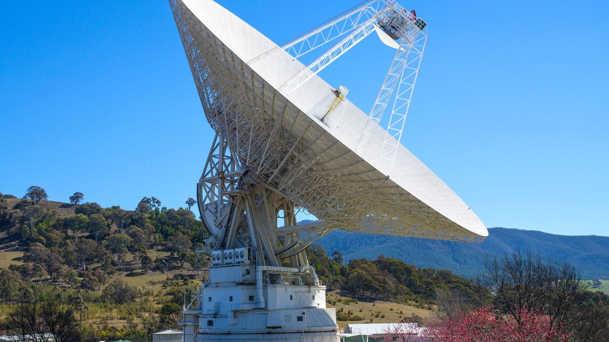
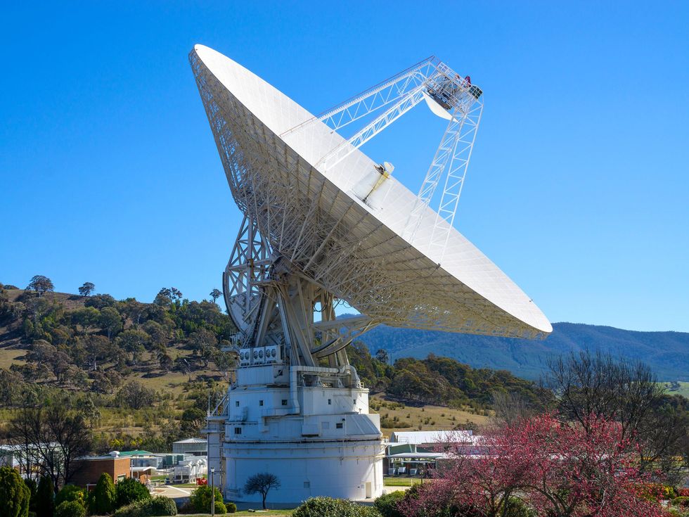
For more than 50 years, Deep Space Station 43 has been an invaluable tool for space probes as they explore our solar system and push into the beyond. The DSS-43 radio antenna, located at the Canberra Deep Space Communication Complex, near Canberra, Australia, keeps open the line of communication between humans and probes during NASA missions.

Today more than 40 percent of all data retrieved by celestial explorers, including Voyagers, New Horizons, and the Mars Curiosity rover, comes through DSS-43.

“As Australia’s largest antenna, DSS-43 has provided two-way communication with dozens of robotic spacecraft,” IEEE President-Elect Kathleen Kramer said during a ceremony where the antenna was recognized as an IEEE Milestone. It has supported missions, Kramer noted, “from the Apollo program and NASA’s Mars exploration rovers such as Spirit and Opportunity to the Voyagers’ grand tour of the solar system.

“In fact,” she said, “it is the only antenna remaining on Earth capable of communicating with Voyager 2.”

Why NASA needed DSS-43

Maintaining two-way contact with spacecraft hurtling billions of kilometers away across the solar system is no mean feat. Researchers at NASA’s Jet Propulsion Laboratory, in Pasadena, Calif., knew that communication with distant space probes would require a dish antenna with unprecedented accuracy. In 1964 they built DSS-42—DSS-43’s predecessor—to support NASA’s Mariner 4 spacecraft as it performed the first-ever successful flyby of Mars in July 1965. The antenna had a 26-meter-diameter dish. Along with two other antennas at JPL and in Spain, DSS-42 obtained the first close-up images of Mars. DSS-42 was retired in 2000.

NASA engineers predicted that to carry out missions beyond Mars, the space agency needed more sensitive antennas. So in 1969 they began work on DSS-43, which has a 64-meter-diameter dish.

DSS-43 was brought online in December 1972—just in time to receive video and audio transmissions sent by Apollo 17 from the surface of the moon. It had greater reach and sensitivity than DSS-42 even after 42’s dish was upgraded in the early 1980s.

The gap between the two antennas’ capabilities widened in 1987, when DSS-43 was equipped with a 70-meter dish in anticipation of Voyager 2’s 1989 encounter with the planet Neptune.

DSS-43 has been indispensable in maintaining contact with the deep-space probe ever since.

The dish’s size isn’t its only remarkable feature. The dish’s manufacturer took great pains to ensure that its surface had no bumps or rough spots. The smoother the dish surface, the better it is at focusing incident waves onto the signal detector so there’s a higher signal-to-noise ratio.

DSS-43 boasts a pointing accuracy of 0.005 degrees (18 arc seconds)—which is important for ensuring that it is pointed directly at the receiver on a distant spacecraft. Voyager 2 broadcasts using a 23-watt radio. But by the time the signals traverse the multibillion-kilometer distance from the heliopause to Earth, their power has faded to a level 20 billion times weaker than what is needed to run a digital watch. Capturing every bit of the incident signals is crucial to gathering useful information from the transmissions.

The antenna has a transmitter capable of 400 kilowatts, with a beam width of 0.0038 degrees. Without the 1987 upgrade, signals sent from DSS-43 to a spacecraft venturing outside the solar system likely never would reach their target.

NASA’s Deep Space Network

The Canberra Deep Space Complex, where DSS-43 resides, is one of three such tracking stations operated by JPL. The other two are DSS-11 at the Goldstone Deep Space Communications Complex near Barstow, Calif., and DSS-63 at the Madrid Deep Space Communications Complex in Robledo de Chavela, Spain. Together, the facilities make up the Deep Space Network, which is the most sensitive scientific telecommunications system on the planet, according to NASA. At any given time, the network is tracking dozens of spacecraft carrying out scientific missions. The three facilities are spaced about 120 degrees longitude apart. The strategic placement ensures that as the Earth rotates, at least one of the antennas has a line of sight to an object being tracked, at least for those close to the plane of the solar system.

But DSS-43 is the only member of the trio that can maintain contact with Voyager 2. Ever since its flyby of Neptune’s moon Triton in 1989, Voyager 2 has been on a trajectory below the plane of the planets, so that it no longer has a line of sight with any radio antennas in the Earth’s Northern Hemisphere.

To ensure that DSS-43 can still place the longest of long-distance calls, the antenna underwent a round of updates in 2020. A new X-band cone was installed. DSS-43 transmits radio signals in the X (8 to 12 gigahertz) and S (2 to 4 GHz) bands; it can receive signals in the X, S, L (1 to 2 GHz), and K (12 to 40 GHz) bands. The dish’s pointing accuracy also was tested and recertified.

Once the updates were completed, test commands were sent to Voyager 2. After about 37 hours, DSS-43 received a response from the space probe confirming it had received the call, and it executed the test commands with no issues.

DSS-43 is still relaying signals between Earth and Voyager 2, which passed the heliopause in 2018 and is now some 20 billion km from Earth.

a group of people smiling and standing around a plaque on a wooden stand with a large white pillar structure in the background 
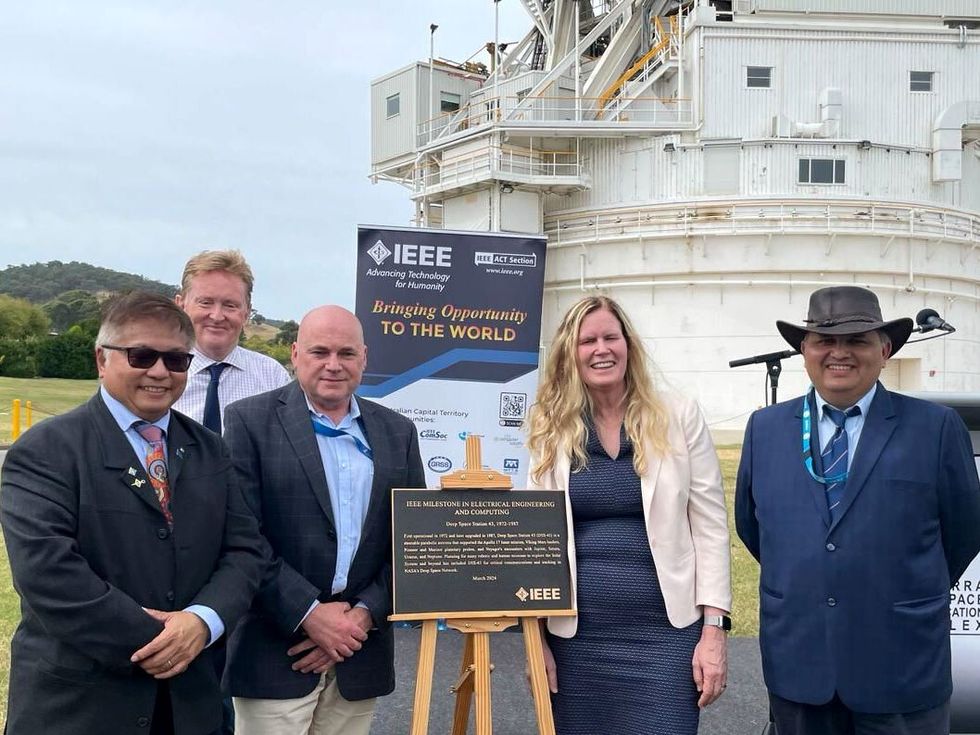
[From left] IEEE Region 10 director Lance Fung, Kevin Furguson, IEEE President-Elect Kathleen Kramer, and Ambarish Natu, past chair of the IEEE Australian Capital Territory Section at the IEEE Milestone dedication ceremony held at the Canberra Deep Space Communication Complex in Australia. Furguson is the director of the complex.Ambarish Natu

Other important missions

DSS-43 has played a vital role in missions closer to Earth as well, including NASA’s Mars Science Laboratory mission. When the space agency sent Curiosity, a golf cart–size rover, to explore the Gale crater and Mount Sharp on Mars in 2011, DSS-43 tracked Curiosity as it made its nail-biting seven-minute descent into Mars’s atmosphere. It took roughly 20 minutes for radio signals to traverse the 320-million km distance between Mars and Earth, and then DSS-43 delivered the good news: The rover had landed safely and was operational.

“NASA plans to send future generations of astronauts from the Moon to Mars, and DSS-43 will play an important role as part of NASA’s Deep Space Network,” says Ambarish Natu, an IEEE senior member who is a past chair of the IEEE Australian Capital Territory (ACT) Section.

DSS-43 was honored with an IEEE Milestone in March during a ceremony held at the Canberra Deep Space Communication Complex.

“This is the second IEEE Milestone recognition given in Australia, and the first for ACT,” Lance Fung, IEEE Region 10 director, said during the ceremony. A plaque recognizing the technology is now displayed at the complex. It reads:

First operational in 1972 and later upgraded in 1987, Deep Space Station 43 (DSS-43) is a steerable parabolic antenna that supported the Apollo 17 lunar mission, Viking Mars landers, Pioneer and Mariner planetary probes, and Voyager’s encounters with Jupiter, Saturn, Uranus, and Neptune. Planning for many robotic and human missions to explore the solar system and beyond has included DSS-43 for critical communications and tracking in NASA’s Deep Space Network.

Administered by the IEEE History Center and supported by donors, the Milestone program recognizes outstanding technical developments around the world. The IEEE Australian Capital Territory Section sponsored the nomination.

The Legacy of the Datapoint 2200 Microcomputer


As the history committee chair of the IEEE Lone Star Section, in San Antonio, Texas, I am responsible for documenting, preserving, and raising the visibility of technologies developed in the local area. One such technology is the Datapoint 2200, a programmable terminal that laid the foundation for the personal computer revolution. Launched in 1970 by Computer Terminal Corp. (CTC) in San Antonio, the machine played a significant role in the early days of microcomputers. The pioneering system integrated a CPU, memory, and input/output devices into a single unit, making it a compact, self-contained device.

Apple, IBM, and other companies are often associated with the popularization of PCs; we must not overlook the groundbreaking innovations introduced by the Datapoint. The machine might have faded from memory, but its influence on the evolution of computing technology cannot be denied. The IEEE Region 5 life members committee honored the machine in 2022 with its Stepping Stone Award, but I would like to make more members aware of the innovations introduced by the machine’s design.

From mainframes to microcomputers

Before the personal computer, there were mainframe computers. The colossal machines, with their bulky, green monitors housed in meticulously cooled rooms, epitomized the forefront of technology at the time. I was fortunate to work with mainframes during my second year as an electrical engineering student in the United Arab Emirates University at Al Ain, Abu Dhabi, in 1986. The machines occupied entire rooms, dwarfing the personal computers we are familiar with today. Accessing the mainframes involved working with text-based terminals that lacked graphical interfaces and had limited capabilities.

Those relatively diminutive terminals that interfaced with the machines often provided a touch of amusement for the students. The mainframe rooms served as social places, fostering interactions, collaborations, and friendly competitions.

Operating the terminals required mastering specific commands and coding languages. The process of submitting computing jobs and waiting for results without immediate feedback could be simultaneously amusing and frustrating. Students often humorously referred to the “black hole,” where their jobs seemed to vanish until the results materialized. Decoding enigmatic error messages became a challenge, yet students found joy in deciphering them and sharing amusing examples.

Despite mainframes’ power, they had restricted processing capabilities and memory compared with today’s computers.

The introduction of personal computers during my senior year was a game-changer. Little did I know that it would eventually lead me to San Antonio, Texas, birthplace of the PC, where I would begin a new chapter of my life.

The first PC

In San Antonio, a group of visionary engineers from NASA founded CTC with the goal of revolutionizing desktop computing. They introduced the Datapoint 3300 as a replacement for Teletype terminals. Led by Phil Ray and Gus Roche, the company later built the first personal desktop computer, the Datapoint 2200. They also developed LAN technology and aimed to replace traditional office equipment with electronic devices operable from a single terminal.

The Datapoint 2200 introduced several design elements that later were adopted by other computer manufacturers. It was one of the first computers to use a keyboard similar to a typewriter’s, and a monitor for user interaction—which became standard input and output devices for personal computers. They set a precedent for user-friendly computer interfaces. The machine also had cassette tape drives for storage, predecessors of disk drives. The computer had options for networking, modems, interfaces, printers, and a card reader.

It used different memory sizes and employed an 8-bit processor architecture. The Datapoint’s CPU was initially intended to be a custom chip, which eventually came to be known as the microprocessor. At the time, no such chips existed, so CTC contracted with Intel to produce one. That chip was the Intel 8008, which evolved into the Intel 8080. Introduced in 1974, the 8080 formed the basis for small computers, according to an entry about early microprocessors in the Engineering and Technology History Wiki.

Those first 8-bit microprocessors are celebrating their 50th anniversary this year.

The 2200 was primarily marketed for business use, and its introduction helped accelerate the adoption of computer systems in a number of industries, according to Lamont Wood, author of Datapoint: The Lost Story of the Texans Who Invented the Personal Computer Revolution.

The machine popularized the concept of computer terminals, which allowed multiple users to access a central computer system remotely, Wood wrote. It also introduced the idea of a terminal as a means of interaction with a central computer, enabling users to input commands and receive output.

The concept laid the groundwork for the development of networking and distributed computing. It eventually led to the creation of LANs and wide-area networks, enabling the sharing of resources and information across organizations. The concept of computer terminals influenced the development of modern networking technologies including the Internet, Wood pointed out.

How Datapoint inspired Apple and IBM

Although the Datapoint 2200 was not a consumer-oriented computer, its design principles and influence played a role in the development of personal computers. Its compact, self-contained nature demonstrated the feasibility and potential of such machines.

The Datapoint sparked the imagination of researchers and entrepreneurs, leading to the widespread availability of personal computers.

Here are a few examples of how manufacturers built upon the foundation laid by the Datapoint 2200:

Apple drew inspiration from early microcomputers. The Apple II, introduced in 1977, was one of the first successful personal computers. It incorporated a keyboard, a monitor, and a cassette tape interface for storage, similar to the Datapoint 2200. In 1984 Apple introduced the Macintosh, which featured a graphical user interface and a mouse, revolutionizing the way users interacted with computers.

IBM entered the personal computer market in 1981. Its PC also was influenced by the design principles of microcomputers. The machine featured an open architecture, allowing for easy expansion and customization. The PC’s success established it as a standard in the industry.

Microsoft played a crucial role in software development for early microcomputers. Its MS-DOS provided a standardized platform for software development and was compatible with the IBM PC and other microcomputers. The operating system helped establish Microsoft as a dominant player in the software industry.

Commodore International, a prominent computer manufacturer in the 1980s, released the Commodore 64 in 1982. It was a successful microcomputer that built upon the concepts of the Datapoint 2200 and other early machines. The Commodore 64 featured an integrated keyboard, color graphics, and sound capabilities, making it a popular choice for gaming and home computing.

Xerox made significant contributions to the advancement of computing interfaces. Its Alto, developed in 1973, introduced the concept of a graphical user interface, with windows, icons, and a mouse for interaction. Although the Alto was not a commercial success, its influence was substantial, and it helped lay the groundwork for GUI-based systems including the Macintosh and Microsoft Windows.

The Datapoint 2200 deserves to be remembered for its contributions to computer history.

The San Antonio Museum of Science and Technology possesses a collection of Datapoint computers, including the original prototypes. The museum also houses a library of archival materials about the machine.

This article has been updated from an earlier version.

How Engineers at Digital Equipment Corp. Saved Ethernet


I’ve enjoyed reading magazine articles about Ethernet’s 50th anniversary, including one in the The Institute. Invented by computer scientists Robert Metcalfe and David Boggs, Ethernet has been extraordinarily impactful. Metcalfe, an IEEE Fellow, received the 1996 IEEE Medal of Honor as well as the 2022 Turing Award from the Association for Computing Machinery for his work. But there is more to the story that is not widely known.

During the 1980s and early 1990s, I led Digital Equipment Corp.’s networking advanced development group in Massachusetts. I was a firsthand witness in what was a period of great opportunity for LAN technologies and intense competition between standardization efforts.

DEC, Intel, and Xerox poised themselves to profit from Ethernet’s launch in the 1970s. But during the 1980s other LAN technologies emerged as competitors. Prime contenders included the token ring, promoted by IBM, and the token bus. (Today Ethernet and both token-based technologies are part of the IEEE 802 family of standards.)

All those LANs have some basic parts in common. One is the 48-bit media access control (MAC) address, a unique number assigned during a computer’s network port manufacturing process. The MAC addresses are used inside the LAN only, but they are critical to its operation. And usually, along with the general-purpose computers on the network, they have at least one special-purpose computer: a router, whose main job is to send data to—and receive it from—the Internet on behalf of all the other computers on the LAN.

In a decades-old conceptual model of networking, the LAN itself (the wires and low-level hardware) is referred to as Layer 2, or the data link layer. Routers mostly deal with another kind of address: a network address that is used both within the LAN and outside it. Many readers likely have heard the terms Internet Protocol and IP address. With some exceptions, the IP address (a network address) in a data packet is sufficient to ensure that packet can be delivered anywhere on the Internet by a sequence of other routers operated by service providers and carriers. Routers and the operations they perform are referred to as Layer 3, or the network layer.

In a token ring LAN, shielded twisted-pair copper wires connect each computer to its upstream and downstream neighbors in an endless ring structure. Each computer forwards data from its upstream neighbor to its downstream one but can send its own data to the network only after it receives a short data packet—a token—from the upstream neighbor. If it has no data to transmit, it just passes the token to its downstream neighbor, and so on.

In a token bus LAN, a coaxial cable connects all the network’s computers, but the wiring doesn’t control the order in which the computers pass the token. The computers agree on the sequence in which they pass the token, forming an endless virtual ring around which data and tokens circulate.

Ethernet, meanwhile, had become synonymous with coaxial cable connections that used a method called carrier sense multiple access with collision detection for managing transmissions. In the CSMA/CD method, computers that want to transmit a data packet first listen to see if another computer is transmitting. If not, the computer sends its packet while listening to determine whether that packet collides with one from another computer. Collisions can happen because signal propagation between computers is not instantaneous. In the case of a collision, the sending computer resends its packet with a delay that has both a random component and an exponentially increasing component that depends on the number of collisions.

The need to detect collisions involves tradeoffs among data rate, physical length, and minimum packet size. Increasing the data rate by an order of magnitude means either reducing the physical length or increasing the minimum packet size by roughly the same factor. The designers of Ethernet had wisely chosen a sweet spot among the tradeoffs: 10 megabits per second and a length of 1,500 meters.

A threat from fiber

Meanwhile, a coalition of companies—including my employer, DEC—was developing a new ANSI LAN standard: the Fiber Distributed Data Interface. The FDDI approach used a variation of the token bus protocol to transmit data over optical fiber, promising speeds of 100 Mb/s, far faster than Ethernet’s 10 Mb/s.

A barrage of technical publications released analyses of the throughputs and latencies of competing LAN technologies under various workloads. Given the results and the much greater network performance demands expected from speedier processors, RAM, and nonvolatile storage, Ethernet’s limited performance was a serious problem.

FDDI seemed a better bet for creating higher speed LANs than Ethernet, although FDDI used expensive components and complex technology, especially for fault recovery. But all shared media access protocols had one or more unattractive features or performance limitations, thanks to the complexity involved in sharing a wire or optical fiber.

A solution emerges

I thought that a better approach than either FDDI or a faster version of Ethernet would be to develop a LAN technology that performed store-and-forward switching.

One evening in 1983, just before leaving work to go home, I visited the office of Mark Kempf, a principal engineer and a member of my team. Mark, one of the best engineers I have ever worked with, had designed the popular and profitable DECServer 100 terminal server, which used the local-area transport (LAT) protocol created by Bruce Mann from DEC’s corporate architecture group. Terminal servers connect groups of dumb terminals, with only RS-232 serial ports, to computer systems with Ethernet ports.

I told Mark about my idea of using store-and-forward switching to increase LAN performance.

The next morning he came in with an idea for a learning bridge (also known as a Layer 2 switch or simply a switch). The bridge would connect to two Ethernet LANs. By listening to all traffic on each LAN, the device would learn the MAC addresses of the computers on both Ethernets (remembering which computer was on which Ethernet) and then selectively forward the appropriate packets between the LANs based upon the destination MAC address. The computers on the two networks didn’t need to know which path their data would take on the extended LAN; to them, the bridge was invisible.

The bridge would need to receive and process some 30,000 packets per second (15,000 pp/s per Ethernet) and decide whether to forward each one. Although the 30,000 pp/s requirement was near the limit of what could be done using the best microprocessor technology of the time, the Motorola 68000, Mark was confident he could build a two-Ethernet bridge using only off-the-shelf components including a specialized hardware engine he would design using programmable array logic (PAL) devices and dedicated static RAM to look up the 48-bit MAC addresses.

Mark’s contributions have not been widely recognized. One exception is the textbook Network Algorithmics by George Varghese.

In a misconfigured network—one with bridges connecting Ethernets in a loop—packets could circulate forever. We felt confident that we could figure out a way to prevent that. In a pinch, a product could ship without the safety feature. And clearly a two-port device was only the starting point. Multiple-port devices could follow, though they would require custom components.

I took our idea to three levels of management, looking for approval to build a prototype of the learning bridge that Mark envisioned. Before the end of the day, we had a green light with the understanding that a product would follow if the prototype was successful.

Developing the bridge

My immediate manager at DEC, Tony Lauck, challenged several engineers and architects to solve the problem of packet looping in misconfigured networks. Within a few days, we had several potential solutions. Radia Perlman, an architect in Tony’s group, provided the clear winner: the spanning tree protocol.

In Perlman’s approach, the bridges detect each other, select a root bridge according to specified criteria, and then compute a minimum spanning tree. An MST is a mathematical structure that, in this case, describes how to efficiently connect LANs and bridges without loops. The MST was then used to place any bridge whose presence would create a loop into backup mode. As a side benefit, it provided automated recovery in the case of a bridge failure.

a big green box with little boxes within with gold dots and different colored wires 
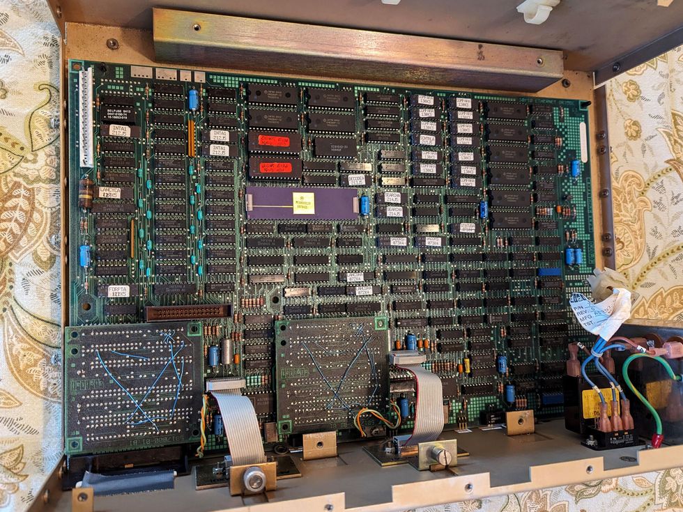
The logic module of a disassembled LANBridge 100, which was released by Digital Equipment Corp. in 1986. Alan Kirby

Mark designed the hardware and timing-sensitive low-level code, while software engineer Bob Shelly wrote the remaining programs. And in 1986, DEC introduced the technology as the LANBridge 100, product code DEBET-AA.

Soon after, DEC developed DEBET-RC, a version that supported a 3-kilometer optical fiber span between bridges. Manuals for some of the DEBET-RCs can be found on the Bitsavers website.

Mark’s idea didn’t replace Ethernet—and that was its brilliance. By allowing store-and-forward switching between existing CSMA/CD coax-based Ethernets, bridges allowed easy upgrades of existing LANs. Since any collision would not propagate beyond the bridge, connecting two Ethernets with a bridge would immediately double the length limit of a single Ethernet cable alone. More importantly, placing computers that communicated heavily with each other on the same Ethernet cable would isolate that traffic to that cable, while the bridge would still allow communication with computers on other Ethernet cables.

That reduced the traffic on both cables, increasing capacity while reducing the frequency of collisions. Taken to its limit, it eventually meant giving each computer its own Ethernet cable, with a multiport bridge connecting them all.

That is what led to a gradual migration away from CSMA/CD over coax to the now ubiquitous copper and fiber links between individual computers and a dedicated switch port.

The speed of the links is no longer limited by the constraints of collision detection. Over time, the change completely transformed how people think of Ethernet.

A bridge could even have ports for different LAN types if the associated packet headers were sufficiently similar.

Our team later developed GIGAswitch, a multiport device supporting both Ethernet and FDDI.

The existence of bridges with increasingly higher performance took the wind out of the sails of those developing new shared media LAN access protocols. FDDI later faded from the marketplace in the face of faster Ethernet versions.

Bridge technology was not without controversy, of course. Some engineers continue to believe that Layer 2 switching is a bad idea and that all you need are faster Layer 3 routers to transfer packets between LANs. At the time, however, IP had not won at the network level, and DECNet, IBM’s SNA, and other network protocols were fighting for dominance. Switching at Layer 2 would work with any network protocol.

Mark received a U.S. patent for the device in 1986. DEC offered to license it on a no-cost basis, allowing any company to use the technology.

That led to an IEEE standardization effort. Established networking companies and startups adopted and began working to improve the switching technology. Other enhancements—including switch-specific ASICs, virtual LANs, and the development of faster and less expensive physical media and associated electronics—steadily contributed to Ethernet’s longevity and popularity.

The lasting value of Ethernet lies not in CSMA/CD or its original coaxial media but in the easily understood and functional service that it provided for protocol designers.

The switches in many home networks today are directly descended from the innovation. And modern data centers have numerous switches with individual ports running between 40 and 800 gigabits per second. The data center switch market alone accounts for more than US $10 billion in annual revenue.

Lauck, my DEC manager, once said that the value of an architecture can be measured by the number of technology generations over which it is useful. By that measure, Ethernet has been enormously successful. The same can be said of Layer 2 switching.

No one knows what would have happened to Ethernet had Mark not invented the learning bridge. Perhaps someone else would have come up with the idea. But it’s also possible that Ethernet would have slowly withered away.

To me, Mark saved Ethernet.

❌