FreshRSS

Zobrazení pro čtení

Jsou dostupné nové články, klikněte pro obnovení stránky.

Xbox Insiders: Everything You Need to Know About Xbox Game Pass Standard

Hey Insiders, let’s talk Game Pass! Starting today, we’re offering Xbox Insiders the option to try out and provide feedback on our new membership, Xbox Game Pass Standard.

We created a new membership option in the Game Pass family to give players more choice in how they discover and play games and provide different prices and plans so players can find what works best for them. For those looking for a larger library with hundreds of games to play on your console, plus all the benefits of Game Pass Core including multiplayer access, Game Pass Standard may be the option for you. Game Pass Standard also includes select member deals and discounts, including up to 50% off select games.  

Hundreds of great games will be available with Game Pass Standard at launch. Players will get access to select titles as part of the new Game Pass Standard library, with more games being added throughout the preview period. Once you join the preview, you can look up the Game Pass Standard library to find your next favorite game.

During this Xbox Insiders preview, you can sign up for just $1. Any renewals during the preview period will also be $1 per month. At launch, Game Pass Standard will be available for $14.99 USD per month (pricing varies by market).

If you’re looking for other console membership options, Game Pass Core has a select collection of over 25 Game Pass games, online multiplayer access, and select member deals and discounts. Game Pass Standard includes everything available in Game Pass Core, plus hundreds of great games. If you are looking for those benefits plus day one titles, specific entries to Game Pass Ultimate library, access to EA Play, cloud gaming, Perks, Quests, and additional discounts for games in the Game Pass library, Game Pass Ultimate might be the best option for you.

Some games coming to Game Pass Ultimate (day one games or other game entries) will not be immediately available with Game Pass Standard and may be added to the library at a future date (can be up to 12 months or more and will vary by title). We’ll continue to share with all Game Pass members when games are being added and available to play for each plan.

 If you’re interested in joining the Insiders preview, please go to the Xbox Insider app located in the Microsoft Store. Terms and Conditions are located there.  Game Pass Core members with less than 2-months stacked onto their account, Game Pass for Console and PC Game Pass players who are a part of the Xbox Insiders program can participate and share their feedback.

As always, huge thank you to all our Insiders – you are a wonderful community, and we appreciate all your feedback.  If you’re an Xbox Insider looking for support, please join our community on the Xbox Insider subreddit. Official Xbox staff, moderators, and fellow Xbox Insiders are there to help.

We’re excited to hear from those that join Game Pass Standard during the preview, and we’ll have more to share on availability for all players coming soon!

The post Xbox Insiders: Everything You Need to Know About Xbox Game Pass Standard appeared first on Xbox Wire.

3.5D: The Great Compromise

The semiconductor industry is converging on 3.5D as the next best option in advanced packaging, a hybrid approach that includes stacking logic chiplets and bonding them separately to a substrate shared by other components.

This assembly model satisfies the need for big increases in performance while sidestepping some of the thorniest issues in heterogeneous integration. It establishes a middle ground between 2.5D, which already is in widespread use inside of data centers, and full 3D-ICs, which the chip industry has been struggling to commercialize for the better part of a decade.

A 3.5D architecture offers several key advantages:

  • It creates enough physical separation to effectively address thermal dissipation and noise.
  • It provides a way to add more SRAM into high-speed designs. SRAM has been the go-to choice for processor cache since the mid-1960s, and remains an essential element for faster processing. But SRAM no longer scales at the same rate as digital transistors, so it is consuming more real estate (in percentage terms) at each new node. And because the size of a reticle is fixed, the best available option is to add area by stacking chiplets vertically.
  • By thinning the interface between processing elements and memory, a 3.5D approach also can shorten the distances that signals need to travel and greatly improve processing speeds well beyond a planar implementation. This is essential with large language models and AI/ML, where the amount of data that needs to be processed quickly is exploding.

Chipmakers still point to fully integrated 3D-ICs as the best performing alternative to a planar SoC, but packing everything into a 3D configuration makes it harder to deal with physical effects. Thermal dissipation is probably the most difficult to contend with. Workloads can vary significantly, creating dynamic thermal gradients and trapping heat in unexpected places, which in turn reduce the lifespan and reliability of chips. On top of that, power and substrate noise become more problematic at each new node, as do concerns about electromagnetic interference.

“What the market has adopted first is high-performance chips, and those produce a lot of heat,” said Marc Swinnen, director of product marketing at Ansys. “They have gone for expensive cooling systems with a huge number of fans and heat sinks, and they have opted for silicon interposers, which arguably are some of the most expensive technologies for connecting chips together. But it also gives the highest performance and is very good for thermal because it matches the coefficient of thermal expansion. Thermal is one of the big reasons that’s been successful. In addition to that, you may want bigger systems with more stuff that you can’t fit on one chip. That’s just a reticle-size limitation. Another is heterogeneous integration, where you want multiple different processes, like an RF process or the I/O, which don’t need to be in 5nm.”

A 3.5D assembly also provides more flexibility to add additional processor cores, and higher yield because known good die can be manufactured and tested separately, a concept first pioneered by Xilinx in 2011 at 28nm.

3.5D is a loose amalgamation of all these approaches. It can include two to three chiplets stacked on top of each other, or even multiple stacks laid out horizontally.

“It’s limited vertical, and not just for thermal reasons,” said Bill Chen, fellow and senior technical advisor at ASE Group. “It’s also for performance reasons. But thermal is the limiting factor, and we’ve talked about many different materials to help with that — diamond and graphene — but that limitation is still there.”

This is why the most likely combination, at least initially, will be processors stacked on SRAM, which simplifies the cooling. The heat generated by high utilization of different processing elements can be removed with heat sinks or liquid cooling. And with one or more thinned out substrates, signals will travel shorter distances, which in turn uses less power to move data back and forth between processors and memory.

“Most likely, this is going to be logic over memory on a logic process,” said Javier DeLaCruz, fellow and senior director of Silicon Ops Engineering at Arm. “These are all contained within an SoC normally, but a portion of that is going to be SRAM, which does not scale very well from node to node. So having logic over memory and a logic process is really the winning solution, and that’s one of the better use cases for 3D because that’s what really shortens your connectivity. A processor generally doesn’t talk to another processor. They talk to each other through memory, so having the memory on a different floor with no latency between them is pretty attractive.”

The SRAM doesn’t necessarily have to be at the same node as the processors advanced node, which also helps with yield, and reliability. At a recent Samsung Foundry event, Taejoong Song, the company’s vice president of foundry business development, showed a roadmap of a 3.5D configuration using a 2nm chiplet stacked on a 4nm chiplet next year, and a 1.4nm chiplet on top of a 2nm chiplet in 2027.


Fig. 1: Samsung’s heterogeneous integration roadmap showing stacked DRAM (HBM), chiplets and co-packaged optics. Source: Samsung Foundry

Intel Foundry’s approach is similar in many ways. “Our 3.5D technology is implemented on a substrate with silicon bridges,” said Kevin O’Buckley, senior vice president and general manager of Foundry Services at Intel. “This is not an incredibly costly, low-yielding, multi-reticle form-factor silicon, or even RDL. We’re using thin silicon slices in a much more cost-efficient fashion to enable that die-to-die connectivity — even stacked die-to-die connectivity — through a silicon bridge. So you get the same advantages of silicon density, the same SI (signal integrity) performance of that bridge without having to put a giant monolithic interposer underneath the whole thing, which is both cost- and capacity-prohibitive. It’s working. It’s in the lab and it’s running.”


Fig. 2: Intel’s 3.5D model. Source: Intel

The strategy here is partly evolutionary — 3.5D has been in R&D for at least several years — and part revolutionary, because thinning out the interconnect layer, figuring out a way to handle these thinner interconnect layers, and how to bond them is still a work in progress. There is a potential for warping, cracking, or other latent defects, and dynamically configuring data paths to maximize throughput is an ongoing challenge. But there have been significant advances in thermal management on two- and three-chiplet stacks.

“There will be multiple solutions,” said C.P. Hung, vice president of corporate R&D at ASE. “For example, besides the device itself and an external heat sink, a lot of people will be adding immersion cooling or local liquid cooling. So for the packaging, you can probably also expect to see the implementation of a vapor chamber, which will add a good interface from the device itself to an external heat sink. With all these challenges, we also need to target a different pitch. For example, nowadays you see mass production with a 45 to 40 pitch. That is a typical bumping solution. We expect the industry to move to a 25 to 20 micron bump pitch. Then, to go further, we need hybrid bonding, which is a less than 10 micron pitch.”


Fig. 3: Today’s interposers support more than 100,000 I/Os at a 45m pitch. Source: ASE

Hybrid bonding solves another thorny problem, which is co-planarity across thousands of micro-bumps. “People are starting to realize that the densities we’re interconnecting require a level of flatness, which the guys who make traditional things to be bonded are having a hard time meeting with reasonable yield,” David Fromm, COO at Promex Industries. “That makes it hard to build them, and the thinking is, ‘So maybe we’ve got to do something else.’ You’re starting to see some of that.”

Taming the Hydra
Managing heat remains a challenge, even with all the latest advances and a 3.5D assembly, but the ability to isolate the thermal effects from other components is the best option available today, and possibly well into the future. Still, there are other issues to contend with. Even 2.5D isn’t easy, and a large percentage of the 2.5D implementations have been bespoke designs by large systems companies with very deep pockets.

One of the big remaining challenges is closing timing so that signals arrive at the right place at the right fraction of a second. This becomes harder as more elements are added into chips, and in a 3.5D or 3D-IC, this can be incredibly complex.

“Timing ultimately is the key,” said Sutirtha Kabir, R&D director at Synopsys. “It’s not guaranteed that at whatever your temperature is, you can use the same library for timing. So the question is how much thermal- and IR-aware timing do you have to do? These are big systems. You have to make sure your sign-off is converging. There are two things coming out. There are a bunch of multi-physics effects that are all clumped together. And yes, you could traditionally do one at a time as sign-off, but that isn’t going to work very well. You need to figure out how to solve these problems simultaneously. Ultimately, you’re doing one design. It’s not one for thermal, one for IR, one for timing. The second thing is the data is exploding. How do you efficiently handle the data, because you cannot wait for days and days of runtime and simulation and analysis?”

Physically assembling these devices isn’t easy, either. “The challenge here is really in the thermal, electrical, and mechanical connection of all these various die with different thicknesses and different coefficients of thermal expansion,” said Intel’s O’Buckley. “So with three die, you’ve got the die and an active base, and those are substantially thinned to enable them to come together. And then EMIB is in the substrate. There’s always intense thermal-mechanical qualification work done to manage not just the assembly, but to ensure in the final assembly — the second-level assembly when this is going through system-level card attach — that this thing stays together.”

And depending upon demands for speed, the interconnects and interconnect materials can change. “Hybrid bonding gives you, by far, the best signal and power density,” said Arm’s DeLaCruz. “And it gives you the best thermal conductivity, because you don’t have that underfill that you would otherwise have to put in between the die, which is a pretty significant barrier. This is likely where the industry will go. It’s just a matter of having the production base.”

Hybrid bonding has been used for years for image sensors using wafer-on-wafer connections. “The tricky part is going into the logic space, where you’re moving from wafer-on-wafer to a die-on-wafer process, which is more complex,” DeLaCruz said. “While it currently would cost more, that’s a temporary problem because there’s not much of an installed base to support it and drive down the cost. There’s really no expensive material or equipment costs.”

Toward mass customization
All of this is leading toward the goal of choosing chiplets from a menu and then rapidly connecting them into some sort of architecture that is proven to work. That may not materialize for years. But commercial chiplets will show up in advanced designs over the next couple years, most likely in high-bandwidth memory with a customized processor in the stack, with more following that path in the future.

At least part of this will depend on how standardized the processes for designing, manufacturing, and testing become. “We’re seeing a lot of 2.5D from customers able to secure silicon interposers,” said Ruben Fuentes, vice president for the Design Center at Amkor Technology. “These customers want to place their chiplets on an interposer, then the full module is placed on a flip-chip substrate package. We also have customers who say they either don’t want to use a silicon interposer or cannot secure them. They prefer an RDL interconnect with S-SWIFT or with S-Connect, which serves as an interposer in very dense areas.”

But with at least a third of these leading designs only for internal use, and the remainder confined to large processor vendors, the rest of the market hasn’t caught up yet. Once it does, that will drive economies of scale and open the door to more complete assembly design kits, commercial chiplets, and more options for customization.

“Everybody is generally going in the same direction,” said Fuentes. “But not everything is the same height. HBMs are pre-packaged and are taller than ICs. HBMs could have 12 or 16 ICs stacked inside. It makes a difference from a co-planarity and thermal standpoint, and metal balancing on different layers. So now vendors are having a hard time processing all this data because suddenly you have these huge databases that are a lot bigger than the standard packaging databases. We’re seeing bridges, S-Connect, SWIFT, and then S-SWIFT. This is new territory, and we’re seeing a performance gap in the packaging tools. There’s work that needs to be done here, but software vendors have been very proactive in finding solutions. Additionally, these packages need to be routed. There is limited automated routing, so a good amount of interactive routing is still required, so it takes a lot of time.”


Fig. 4: Packaging roadmap showing bridge and hybrid bonding connections for modules and chiplets, respectively. Source: Amkor Technology

What’s missing
The key challenges ahead for 3.5D are proven reliability and customizability — requirements that are seemingly contradictory, and which are beyond the control of any single company. There are four major pieces to making all of this work.

EDA is the first important piece of the puzzle, and the challenge extends just beyond a single chip. “The IC designers have to think about a lot of things concurrently, like thermal, signal integrity, and power integrity,” said Keith Lanier, technical product management director at Synopsys. “But even beyond that, there’s a new paradigm in terms of how people need to work. Traditional packaging folks and IC designers need to work closely together to make these 3.5D designs successful.”

It’s not just about doing more with the same or fewer people. It’s doing more with different people, too. “It’s understanding the architecture definition, the functional requirements, constraints, and having those well-defined,” Lanier said. “But then it’s also feasibility, which includes partitioning and technology selection, and then prototyping and floor-planning. This is lots and lots of data that is required to be generated, and you need analysis-driven exploration, design, and implementation. And AI will be required to help designers and system design teams manage the sheer complexity of these 3.5D designs.”

Process/assembly design kits are a second critical piece, and this is likely to be split between the foundries and the OSATs. “If the customer wants a silicon interposer for a 2.5D package, it would be up to the foundry that’s going to manufacture the interposer to provide the PDK. We would provide the PDK for all of our products, such as S-SWIFT and S-Connect,” said Amkor’s Fuentes.

Setting realistic parameters is the third piece of the puzzle. While the type of processing elements and some of the analog functions may change — particularly those involving power and communication — most of the components will remain the same. That determines what can be pre-built and pre-tested, and the speed and ease of assembly.

“A lot of the standards that are being deployed, like UCIe interfaces and HBM interfaces are heading to where 20% is customization and 80% is on the shelf,” said Intel’s O’Buckley. “But we aren’t there today. At the scale that our customers are deploying these products, the economics of spending that extra time to optimize an implementation is a decimal point. It’s not leveraging 80/20 standards. We’ll get there. But most of these designs you can count on your fingers and toes because of the cost and scale required to do them. And until the infrastructure for standards-based chiplets gets mature, the barrier of entry for companies that want to do this without that scale is just too high. Still, it is going to happen.”

Ensuring processes are consistent is the fourth piece of the puzzle. The tools and the individual processes don’t need to change. “The customer has a ‘target’ for the outcome they want for a particular tool, which typically is a critical dimension measured by a metrology tool,” said David Park, vice president of marketing at Tignis. “As long as there is some ‘measurement’ that determines the goodness of some outcome, which typically is the result of a process step, we can either predict the bad outcome — and engineers have to take some corrective or preventive action — or we can optimize the recipe of that tool in real time to keep the result in the range they want.”

Park noted there is a recipe that controls the inputs. “The tool does whatever it is supposed to do,” he said. “Then you measure the output to see how far you deviated from the acceptable output.”

The challenge is that inside of a 3.5D system, what is considered acceptable output is still being defined. There are many processes with different tolerances. Defining what is consistent enough will require a broad understanding of how all the pieces work together under specific workloads, and where the potential weaknesses are that need to be adjusted.

“One of the problems here is as these densities get higher and the copper pillars get smaller, the amount of space you need between the pillar and the substrate have to be highly controlled,” said Dick Otte, president and CEO of Promex. “There’s a conflict — not so much with how you fabricate the chip, because it usually has the copper pillars on it — but with the substrate. A lot of the substrate technologies are not inherently flat. It’s the same issue with glass. You’ve got a really nice flat piece of glass. The first thing you’re going to do is put down a layer of metal and you’re going to pattern it. And then you put down a layer of dielectric, and suddenly you’ve got a lump where the conductor goes. And now, where do you put the contact points? So you always have the one plan which is going to be the contact point where all the pillars come in. But what if I only need one layer and I don’t need three?”

Conclusion
For the past decade, the chip industry has been trying to figure out a way to balance faster processing, domain-specific designs, limited reticle size, and the enormous cost of scaling an SoC. After investigating nearly every possible packaging approach, interconnect, power delivery method, substrate and dielectric material, 3.5D has emerged as the front runner — at least for now.

This approach provides the chip industry with a common thread on which to begin developing assembly design kits, commercial chiplets, and to fill in the missing tools and services throughout the supply chain. Whether this ultimately becomes a springboard for full 3D-ICs, or a platform on which to use 3D stacking more effectively, remains to be seen. But for the foreseeable future, large chipmakers have converged on a path forward to provide orders of magnitude performance improvements and a way to contain costs. The rest of the industry will be working to smooth out that path for years to come.

Related Reading
Intel Vs. Samsung Vs. TSMC
Foundry competition heats up in three dimensions and with novel technologies as planar scaling benefits diminish.
3D Metrology Meets Its Match In 3D Chips And Packages
Next-generation tools take on precision challenges in three dimensions.
Design Flow Challenged By 3D-IC Process, Thermal Variation
Rethinking traditional workflows by shifting left can help solve persistent problems caused by process and thermal variations.
Floor-Planning Evolves Into The Chiplet Era
Automatically mitigating thermal issues becomes a top priority in heterogeneous designs.

The post 3.5D: The Great Compromise appeared first on Semiconductor Engineering.

A New Low-Cost HW-Counterbased RowHammer Mitigation Technique

A technical paper titled “ABACuS: All-Bank Activation Counters for Scalable and Low Overhead RowHammer Mitigation” was presented at the August 2024 USENIX Security Symposium by researchers at ETH Zurich.

Abstract:

“We introduce ABACuS, a new low-cost hardware-counterbased RowHammer mitigation technique that performance-, energy-, and area-efficiently scales with worsening RowHammer vulnerability. We observe that both benign workloads and RowHammer attacks tend to access DRAM rows with the same row address in multiple DRAM banks at around the same time. Based on this observation, ABACuS’s key idea is to use a single shared row activation counter to track activations to the rows with the same row address in all DRAM banks. Unlike state-of-the-art RowHammer mitigation mechanisms that implement a separate row activation counter for each DRAM bank, ABACuS implements fewer counters (e.g., only one) to track an equal number of aggressor rows.

Our comprehensive evaluations show that ABACuS securely prevents RowHammer bitflips at low performance/energy overhead and low area cost. We compare ABACuS to four state-of-the-art mitigation mechanisms. At a nearfuture RowHammer threshold of 1000, ABACuS incurs only 0.58% (0.77%) performance and 1.66% (2.12%) DRAM energy overheads, averaged across 62 single-core (8-core) workloads, requiring only 9.47 KiB of storage per DRAM rank. At the RowHammer threshold of 1000, the best prior lowarea-cost mitigation mechanism incurs 1.80% higher average performance overhead than ABACuS, while ABACuS requires 2.50× smaller chip area to implement. At a future RowHammer threshold of 125, ABACuS performs very similarly to (within 0.38% of the performance of) the best prior performance- and energy-efficient RowHammer mitigation mechanism while requiring 22.72× smaller chip area. We show that ABACuS’s performance scales well with the number of DRAM banks. At the RowHammer threshold of 125, ABACuS incurs 1.58%, 1.50%, and 2.60% performance overheads for 16-, 32-, and 64-bank systems across all single-core workloads, respectively. ABACuS is freely and openly available at https://github.com/CMU-SAFARI/ABACuS.”

Find the technical paper here.

Olgun, Ataberk, Yahya Can Tugrul, Nisa Bostanci, Ismail Emir Yuksel, Haocong Luo, Steve Rhyner, Abdullah Giray Yaglikci, Geraldo F. Oliveira, and Onur Mutlu. “Abacus: All-bank activation counters for scalable and low overhead rowhammer mitigation.” In USENIX Security. 2024.

Further Reading
Securing DRAM Against Evolving Rowhammer Threats
A multi-layered, system-level approach is crucial to DRAM protection.

The post A New Low-Cost HW-Counterbased RowHammer Mitigation Technique appeared first on Semiconductor Engineering.

Samsung’s new smartphone memory chip is as thin as a fingernail

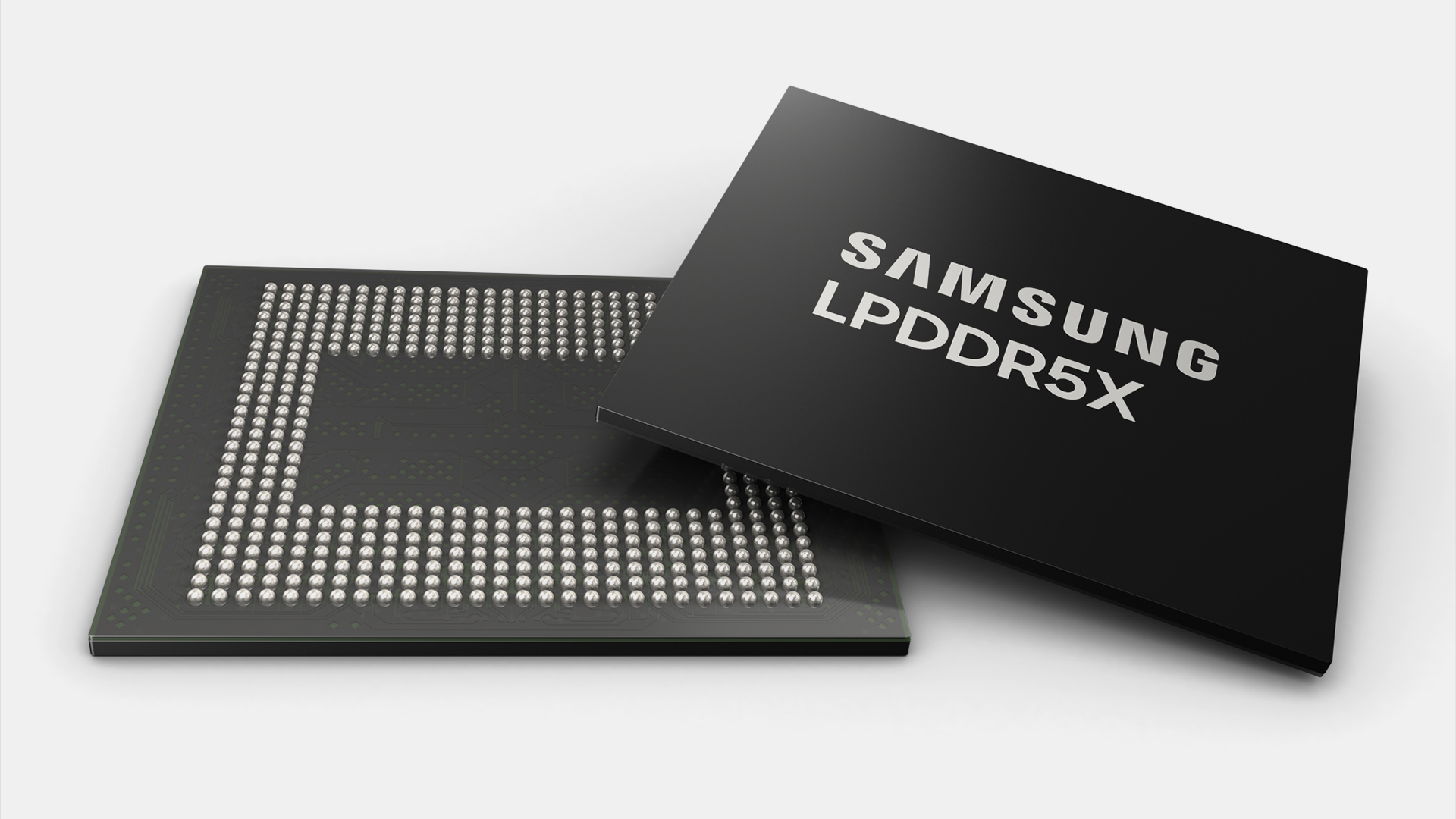
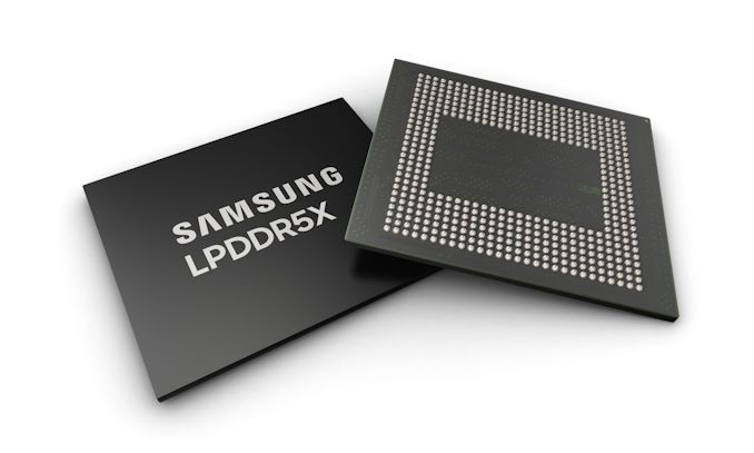
Samsung has unveiled the world's thinnest LPDDR5X DRAM chip, which is just 0.65mm thin, or as thin as a fingernail. This chip is made for high-end smartphones, which typically have an onboard neural processing unit (NPU) for on-device AI processing.

Samsung's newest LPDDR5X DRAM is just 0.65mm thin, making it the world's thinnest in its segment

Samsung LPDDR5X DRAM Chip

The newest LPDDR5X DRAM chip from Samsung is the world's thinnest 12nm-class chip. It is available in 12GB and 16GB capacities. This chip is made using four stacked layers, each containing two LPDDR DRAM chips. Due to its thin profile, it offers more space in mobile devices, allowing for a better thermal design. According to Samsung, its new memory chip improves heat resistance by up to 21.2% compared to the previous-generation LPDDR5X chip.

Samsung LPDDR5X DRAM Thinnest 0.65mm

Samsung optimized the printed circuit board (PCB), epoxy molding compound (EMC), and the back-lapping process to minimize the chip's height. The company plans to start supplying its new chip to smartphone manufacturers soon. It also announced that it will soon start making 24GB (6-layer) and 32GB (8-layer) LPDDR DRAM chips for future mobile devices.

YongCheol Bae, the Executive VP of Samsung's Memory Product Planning team, said, “Samsung’s LPDDR5X DRAM sets a new standard for high-performance on-device AI solutions, offering not only superior LPDDR performance but also advanced thermal management in an ultra-compact package. We are committed to continuous innovation through close collaboration with our customers, delivering solutions that meet the future needs of the low-power DRAM market.

Samsung LPDDR5X DRAM Thinnest Scale Samsung LPDDR5X DRAM Chip Connectors

Image Credits: Samsung

The post Samsung’s new smartphone memory chip is as thin as a fingernail appeared first on SamMobile.

Are You Ready For HBM4? A Silicon Lifecycle Management (SLM) Perspective

Many factors are driving system-on-chip (SoC) developers to adopt multi-die technology, in which multiple dies are stacked in a three-dimensional (3D) configuration. Multi-die systems may make power and thermal issues more complex, and they have required major innovations in electronic design automation (EDA) implementation and test tools. These challenges are more than offset by the advantages of over traditional 2D designs, including:

  • Reducing overall area
  • Achieving much higher pin densities
  • Reusing existing proven dies
  • Mixing heterogeneous die technologies
  • Quickly creating derivative designs for new applications

One of the most common uses of multi-die design is the interconnection of memory stacks and processors such as CPUs and GPUs. High Bandwidth Memory (HBM) is a standard interface specifically for 3D-stacked DRAM dies. It was defined by the JEDEC Solid State Technology Association in 2013, followed by HBM2 in 2016 and HBM3 in 2022. Many multi-die projects have used this standard for caches in advanced CPUs and other system-on-chip (SoC) designs used in high-end applications such as data centers, high-performance computing (HPC), and artificial intelligence (AI) processing.

Fig. 1: Example of a current HBM-based SoC.

JEDEC recently announced that it is nearing completion of HBM4 and published preliminary specifications. HBM4 has been developed to enhance data processing rates while maintaining higher bandwidth, lower power consumption, and increased capacity per die/stack. The initial agreement calls for speed bins up to 6.4 Gbps, although this will increase as memory vendors develop new chips and refine the technology. This speed will benefit applications that require efficient handling of large datasets and complex calculations.

HBM4 is introducing a doubled channel count per stack over HBM3. The new version of the standard features a 2048-bit memory interface, as compared to 1024 bits in previous versions, as shown in figure 1. This intent is to double the number of bits without increasing the footprint of HBM memory stacks, thus doubling the interconnection density as well.

Different memory configurations will require various interposers to accommodate the differing footprints. HBM4 will specify 24 Gb and 32 Gb layers, with options for supporting 4-high, 8-high, 12-high and 16-high TSV stacks. As an example configuration, a 16-high based on 32 Gb layers will offer a capacity of 64 GB, which means that a processor with four memory modules can support 256 GB of memory with a peak bandwidth of 6.56 TB/s using an 8,192-bit interface.

The move from HBM3 to HBM4 will require further evolution in multi-die support across a wide range of EDA tools. The 2048-bit memory interface requires a significant increase in the number of through-silicon vias (TSVs) routed through a memory stack. This will mean shrinking the external bump pitch as the total number of micro bumps increases significantly. In addition, support for 16-high TSV stacks brings new complexity in wiring up an even larger number of DRAM dies without defects.

Test challenges are likely to be a dominant part of the transition. Any signal integrity issues after assembly and multi-die packaging become more difficult to diagnose and debug since probing is not feasible. Further, some defects may marginally pass production/manufacturing test but subsequently fail in the field. Thus, test of the future HBM4-based subsystem needs to be accomplished not just at production test but also in-system to account for aging-related defects.

Being able to monitor real-time data during mission mode operation in the field is greatly preferable to having to take the system offline for unplanned service. This “predictive maintenance” allows the end user to be proactive rather than reactive. HBM provides capabilities for in-system repair, for example swapping out a bad lane. Even if a defect requires physical hardware repair, detecting it before system failure enables scheduled maintenance rather than unplanned downtime.

As shown in figure 1, HBM systems typically have a base die that includes an HBM controller, a basic/fixed test engine provided by the DRAM vendor, and Direct Access (DA) ports. The new industry trend is for the base die to be manufactured on a standard logic process rather than the DRAM process. The SoC designer should include in the base die a flexible built-in self-test (BIST) engine that allows different algorithms to be used to trade off high coverage versus test time depending on the scenario.

This engine must be programmable to handle different latencies, address ranges, and timing of test operations that vary across DRAM vendors. It may also need to support post-package repair (PPR) for HBM DRAM to delay any “truck roll-out” for in-field service. The diagnostics performed by the BIST engine must be precise, showing the failing bank, row address, column address, etc. if there is a defect detected in the DRAM stack. Figure 2 shows an example.

Fig. 2: Example fault diagnosis for HBM stack.

As an industry leader in multi-die EDA and IP solutions, Synopsys provides all the technology needed for HBM manufacturing yield optimization and in-field silicon health monitoring. Signal Integrity Monitors (SIMs) are embedded in physical layer (PHY) IP blocks for on-demand signal quality measurement for interconnects. This allows users to create 1D eye diagrams for interconnect signals during both production test and in-field operation. SIMs measure timing margins, enable HBM lane test/repair, and mitigate against silent data corruption (SDC), part of an effective silicon lifecycle management (SLM) solution.

Synopsys SMS ext-RAM is a programmable and synthesizable engine that performs test, repair, and diagnostics for memory systems, including HBM. SMS ext-RAM ensures high test coverage and supports power-on self-test (POST) with the flexibility to run custom memory algorithms in-field. As shown in figure 2, it detects a wide range of defects in memory dies, including stuck-at faults, read destructive faults, write destructive faults, deceptive read destructive faults, and row hammering.

A real world case study of a project using HBM with the Synopsys solutions is available. These solutions are scaling to support the emerging HBM4 standard, ensuring continued success.

The post Are You Ready For HBM4? A Silicon Lifecycle Management (SLM) Perspective appeared first on Semiconductor Engineering.

Metrology And Inspection For The Chiplet Era

New developments and innovations in metrology and inspection will enable chipmakers to identify and address defects faster and with greater accuracy than ever before, all of which will be required at future process nodes and in densely-packed assemblies of chiplets.

These advances will affect both front-end and back-end processes, providing increased precision and efficiency, combined with artificial intelligence/machine learning and big data analytics. These kinds of improvements will be crucial for meeting the industry’s changing needs, enabling deeper insights and more accurate measurements at rates suitable for high-volume manufacturing. But gaps still need to be filled, and new ones are likely to show up as new nodes and processes are rolled out.

“As semiconductor devices become more complex, the demand for high-resolution, high-accuracy metrology tools increases,” says Brad Perkins, product line manager at Nordson Test & Inspection. “We need new tools and techniques that can keep up with shrinking geometries and more intricate designs.”

The shift to high-NA EUV lithography (0.55 NA EUV) at the 2nm node and beyond is expected to exacerbate stochastic variability, demanding more robust metrology solutions on the front end. Traditional critical dimension (CD) measurements alone are insufficient for the level of analysis required. Comprehensive metrics, including line-edge roughness (LER), line-width roughness (LWR), local edge-placement error (LEPE), and local CD uniformity (LCDU), alongside CD measurements, are necessary for ensuring the integrity and performance of advanced semiconductor devices. These metrics require sophisticated tools that can capture and analyze tiny variations at the nanometer scale, where even slight discrepancies can significantly impact device functionality and yield.

“Metrology is now at the forefront of yield, especially considering the current demands for DRAM and HBM,” says Hamed Sadeghian, president and CEO of Nearfield Instruments. “The next generations of HBMs are approaching a stage where hybrid bonding will be essential due to the increasing stack thickness. Hybrid bonding requires high resolutions in vertical directions to ensure all pads, and the surface height versus the dielectric, remain within nanometer-scale process windows. Consequently, the tools used must be one order of magnitude more precise.”

To address these challenges, companies are developing hybrid metrology systems that combine various measurement techniques for a comprehensive data set. Integrating scatterometry, electron microscopy, and/or atomic force microscopy allows for more thorough analysis of critical features. Moreover, AI and ML algorithms enhance the predictive capabilities of these tools, enabling process adjustments.

“Our customers who are pushing into more advanced technology nodes are desperate to understand what’s driving their yield,” says Ronald Chaffee, senior director of applications engineering at NI/Emerson Test & Measurement. “They may not know what all the issues are, but they are gathering all possible data — metrology, AEOI, and any measurable parameters — and seeking correlations.”

Traditional methods for defect detection, pattern recognition, and quality control typically used spatial pattern-recognition modules and wafer image-based algorithms to address wafer-level issues. “However, we need to advance beyond these techniques,” says Prasad Bachiraju, senior director of business development at Onto Innovation. “Our observations show that about 20% of wafers have systematic issues that can limit yield, with nearly 4% being new additions. There is a pressing need for advanced metrology for in-line monitoring to achieve zero-defect manufacturing.”

Several companies recently announced metrology innovations to provide more precise inspections, particularly for difficult-to-see areas, edge effects, and highly reflective surfaces.

Nordson unveiled its AMI SpinSAM acoustic rotary scan system. The system represents a significant departure from traditional raster scan methods, utilizing a rotational scanning approach. Rather than moving the wafer in an x,y pattern relative to a stationary lens, the wafer spins, similar to a record player. This reduces motion over the wafer and increases inspection speed, negating the need for image stitching and improving image quality.

“For years, we’d been trying to figure out this technique, and it’s gratifying to finally achieve it. It’s something we’ve always thought would be incredibly beneficial,” says Perkins. “The SpinSAM is designed primarily to enhance inspection speed and efficiency, addressing the common industry demand for more product throughput and better edge inspection capabilities.”

Meanwhile, Nearfield Instruments introduced a multi-head atomic force microscopy (AFM) system called QUADRA. It is a high-throughput, non-destructive metrology tool for HVM that features a novel multi-miniaturized AFM head architecture. Nearfield claims the parallel independent multi-head scanner can deliver a 100-fold throughput advantage versus conventional single-probe AFM tools. This architecture allows for precise measurements of high-aspect-ratio structures and complex 3D features, critical for advanced memory (3D NAND, DRAM, HBM) and logic processes.


Fig. 1: Image capture comparison of standard AFM and multi-head AFM. Source: Nearfield Instruments

In April, Onto Innovation debuted an advancement in subsurface defect inspection technology with the release of its Dragonfly G3 inspection system. The new system allows for 100% wafer inspection, targeting subsurface defects that can cause yield losses, such as micro-cracks and other hidden flaws that may lead to entire wafers breaking during subsequent processing steps. The Dragonfly G3 utilizes novel infrared (IR) technology combined with specially designed algorithms to detect these defects, which previously were undetectable in a production environment. This new capability supports HBM, advanced logic, and various specialty segments, and aims to improve final yield and cost savings by reducing scrapped wafers and die stacks.

More recently, researchers at the Paul Scherrer Institute announced a high-performance X-ray tomography technique using burst ptychography. This new method can provide non-destructive, detailed views of nanostructures as small as 4nm in materials like silicon and metals at a fast acquisition rate of 14,000 resolution elements per seconds. The tomographic back-propagation reconstruction allows imaging of samples up to ten times larger than the conventional depth of field.

There are other technologies and techniques for improving metrology in semiconductor manufacturing, as well, including wafer-level ultrasonic inspection, which involves flipping the wafer to inspect from the other side. New acoustic microscopy techniques, such as scanning acoustic microscopy (SAM) and time-of-flight acoustic microscopy (TOF-AM), enable the detection and characterization of very small defects, such as voids, delaminations, and cracks within thin films and interfaces.

“We used to look at 80 to 100 micron resist films, but with 3D integrated packaging, we’re now dealing with films that are 160 to 240 microns—very thick resist films,” says Christopher Claypool, senior application scientist at Bruker OCD. “In TSVs and microbumps, the dominant technique today is white light interferometry, which provides profile information. While it has some advantages, its throughput is slow, and it’s a focus-based technique. This limitation makes it difficult to measure TSV structures smaller than four or five microns in diameter.”

Acoustic metrology tools equipped with the newest generation of focal length transducers (FLTs) can focus acoustic waves with precision down to a few nanometers, allowing for non-destructive detailed inspection of edge defects and critical stress points. This capability is particularly useful for identifying small-scale defects that might be missed by other inspection methods.

The development and integration of smart sensors in metrology equipment is instrumental in collecting the vast amounts of data needed for precise measurement and quality control. These sensors are highly sensitive and capable of operating under various environmental conditions, ensuring consistent performance. One significant advantage of smart sensors is their ability to facilitate predictive maintenance. By continuously monitoring the health and performance of metrology equipment, these sensors can predict potential failures and schedule maintenance before significant downtime occurs. This capability enhances the reliability of the equipment, reduces maintenance costs, and improves overall operational efficiency.

Smart sensors also are being developed to integrate seamlessly with metrology systems, offering real-time data collection and analysis. These sensors can monitor various parameters throughout the manufacturing process, providing continuous feedback and enabling quick adjustments to prevent defects. Smart sensors, combined with big data platforms and advanced data analytics, allow for more efficient and accurate defect detection and classification.

Critical stress points

A persistent challenge in semiconductor metrology is the identification and inspection of defects at critical stress points, particularly at the silicon edges. For bonded wafers, it’s at the outer ring of the wafer. For chip-on-wafer packaging, it’s at the edge of the chips. These edge defects are particularly problematic because they occur at the highest stress points from the neutral axis, making them more prone to failures. As semiconductor devices continue to involve more intricate packaging techniques, such as chip-on-wafer and wafer-level packaging, the focus on edge inspection becomes even more critical.

“When defects happen in a factory, you need imaging that can detect and classify them,” says Onto’s Bachiraju. “Then you need to find the root causes of where they’re coming from, and for that you need the entire data integration and a big data platform to help with faster analysis.”

Another significant challenge in semiconductor metrology is ensuring the reliability of known good die (KGD), especially as advanced packaging techniques and chiplets become more prevalent. Ensuring that every chip/chiplet in a stacked die configuration is of high quality is essential for maintaining yield and performance, but the speed of metrology processes is a constant concern. This leads to a balancing act between thoroughness and efficiency. The industry continuously seeks to develop faster machines that can handle the increasing volume and complexity of inspections without compromising accuracy. In this race, innovations in data processing and analysis are key to achieving quicker results.

“Customers would like, generally, 100% inspection for a lot of those processes because of the known good die, but it’s cost-prohibitive because the machines just can’t run fast enough,” says Nordson’s Perkins.

Metrology and Industry 4.0

Industry 4.0 — a term introduced in Germany in 2011 for the fourth industrial revolution, and called smart manufacturing in the U.S. — emphasizes the integration of digital technologies such as the Internet of Things, artificial intelligence, and big data analytics into manufacturing processes. Unlike past revolutions driven by mechanization, electrification, and computerization, Industry 4.0 focuses on connectivity, data, and automation to enhance manufacturing capabilities and efficiency.

“The better the data integration is, the more efficient the yield ramp,” says Dieter Rathei, CEO of DR Yield. “It’s essential to integrate all available data into the system for effective monitoring and analysis.”

In semiconductor manufacturing, this shift toward Industry 4.0 is particularly transformative, driven by the increasing complexity of semiconductor devices and the demand for higher precision and yield. Traditional metrology methods, heavily reliant on manual processes and limited automation, are evolving into highly interconnected systems that enable real-time data sharing and decision-making across the entire production chain.

“There haven’t been many tools to consolidate different data types into a single platform,” says NI’s Chaffee. “Historically, yield management systems focused on testing, while FDC or process systems concentrated on the process itself, without correlating the two. As manufacturers push into the 5, 3, and 2nm spaces, they’re discovering that defect density alone isn’t the sole governing factor. Process control is also crucial. By integrating all data, even the most complex correlations that a human might miss can be identified by AI and ML. The goal is to use machine learning to detect patterns or connections that could help control and optimize the manufacturing process.”

IoT forms the backbone of Industry 4.0 by connecting various devices, sensors, and systems within the manufacturing environment. In semiconductor manufacturing, IoT enables seamless communication between metrology tools, production equipment, and factory management systems. This interconnected network facilitates real-time monitoring and control of manufacturing processes, allowing for immediate adjustments and optimization.

“You need to integrate information from various sources, including sensors, metrology tools, and test structures, to build predictive models that enhance process control and yield improvement,” says Michael Yu, vice president of advanced solutions at PDF Solutions. “This holistic approach allows you to identify patterns and correlations that were previously undetectable.”

AI and ML are pivotal in processing and analyzing the vast amounts of data generated in a smart factory. These technologies can identify patterns, predict equipment failures, and optimize process parameters with a level of precision and speed unattainable by human operators alone. In semiconductor manufacturing, AI-driven analytics enhance process control, improve yield rates, and reduce downtime. “One of the major trends we see is the integration of artificial intelligence and machine learning into metrology tools,” says Perkins. “This helps in making sense of the vast amounts of data generated and enables more accurate and efficient measurements.”

AI’s role extends further as it assists in discovering anomalies within the production process that might have gone unnoticed with traditional methods. AI algorithms integrated into metrology systems can dynamically adjust processes in real-time, ensuring that deviations are corrected before they affect the end yield. This incorporation of AI minimizes defect rates and enhances overall production quality.

“Our experience has shown that in the past 20 years, machine learning and AI algorithms have been critical for automatic data classification and die classification,” says Bachiraju. “This has significantly improved the efficiency and accuracy of our metrology tools.”

Big data analytics complements AI/ML by providing the infrastructure necessary to handle and interpret massive datasets. In semiconductor manufacturing, big data analytics enables the extraction of actionable insights from data generated by IoT devices and production systems. This capability is crucial for predictive maintenance, quality control, and continuous process improvement.

“With big data, we can identify patterns and correlations that were previously impossible to detect, leading to better process control and yield improvement,” says Perkins.

Big data analytics also helps in understanding the lifecycle of semiconductor devices from production to field deployment. By analyzing product performance data over time, manufacturers can predict potential failures and enhance product designs, increasing reliability and lifecycle management.

“In the next decade, we see a lot of opportunities for AI,” says DR Yield’s Rathei. “The foundation for these advancements is the availability of comprehensive data. AI models need extensive data for training. Once all the data is available, we can experiment with different models and ideas. The ingenuity of engineers, combined with new tools, will drive exponential progress in this field.”

Metrology gaps remain

Despite recent advancements in metrology, analytics, and AI/ML, several gaps still remain, particularly in the context of high-volume manufacturing (HVM) and next-generation devices. The U.S. Commerce Department’s CHIPS R&D Metrology Program, along with industry stakeholders, have highlighted seven “grand challenges,” areas where current metrology capabilities fall short:

Metrology for materials purity and properties: There is a critical need for new measurements and standards to ensure the purity and physical properties of materials used in semiconductor manufacturing. Current techniques lack the sensitivity and throughput required to detect particles and contaminants throughout the supply chain.

Advanced metrology for future manufacturing: Next-generation semiconductor devices, such as gate-all-around (GAA) FETs and complementary FETs (CFETs), require breakthroughs in both physical and computational metrology. Existing tools are not yet capable of providing the resolution, sensitivity, and accuracy needed to characterize the intricate features and complex structures of these devices. This includes non-destructive techniques for characterizing defects and impurities at the nanoscale.

“There is a secondary challenge with some of the equipment in metrology, which often involves sampling data from single points on a wafer, much like heat test data that only covers specific sites,” says Chaffee. “To be meaningful, we need to move beyond sampling methods and find creative ways to gather information from every wafer, integrating it into a model. This involves building a knowledge base that can help in detecting patterns and correlations, which humans alone might miss. The key is to leverage AI and machine learning to identify these correlations and make sense of them, especially as we push into the 5, 3, and 2nm spaces. This process is iterative and requires a holistic approach, encompassing various data points and correlating them to understand the physical boundaries and the impact on the final product.”

Metrology for advanced packaging: The integration of sophisticated components and novel materials in advanced packaging technologies presents significant metrology challenges. There is a need for rapid, in-situ measurements to verify interfaces, subsurface interconnects, and internal 3D structures. Current methods do not adequately address issues such as warpage, voids, substrate yield, and adhesion, which are critical for the reliability and performance of advanced packages.

Modeling and simulating semiconductor materials, designs, and components: Modeling and simulating semiconductor processes require advanced computational models and data analysis tools. Current capabilities are limited in their ability to seamlessly integrate the entire semiconductor value chain, from materials inputs to system assembly. There is a need for standards and validation tools to support digital twins and other advanced simulation techniques that can optimize process development and control.

“Predictive analytics is particularly important,” says Chaffee. “They aim to determine the probability of any given die on a wafer being the best yielding or presenting issues. By integrating various data points and running different scenarios, they can identify and understand how specific equipment combinations, sequences and processes enhance yields.”

Modeling and simulating semiconductor processes: Current capabilities are limited in their ability to seamlessly integrate the entire semiconductor value chain, from materials inputs to system assembly. There is a need for standards and validation tools to support digital twins and other advanced simulation techniques that can optimize process development and control.

“Part of the problem comes from the back-end packaging and assembly process, but another part of the problem can originate from the quality of the wafer itself, which is determined during the front-end process,” says PDF’s Yu. “An effective ML model needs to incorporate both front-end and back-end information, including data from equipment sensors, metrology, and structured test information, to make accurate predictions and take proactive actions to correct the process.”

Standardizing new materials and processes: The development of future information and communication technologies hinges on the creation of new standards and validation methods. Current reference materials and calibration services do not meet the requirements for next-generation materials and processes, such as those used in advanced packaging and heterogeneous integration. This gap hampers the industry’s ability to innovate and maintain competitive production capabilities.

Metrology to enhance security and provenance of components and products: With the increasing complexity of the semiconductor supply chain, there is a need for metrology solutions that can ensure the security and provenance of components and products. This involves developing methods to trace materials and processes throughout the manufacturing lifecycle to prevent counterfeiting and ensure compliance with regulatory standards.

“The focus on security and sharing changes the supplier relationship into more of a partnership and less of a confrontation,” says Chaffee. “Historically, there’s always been a concern of data flowing across that boundary. People are very protective about their process, and other people are very protective about their product. But once you start pushing into the deep sub-micron space, those barriers have to come down. The die are too expensive for them not to communicate, but they can still do so while protecting their IP. Companies are starting to realize that by sharing parametric test information securely, they can achieve better yield management and process optimization without compromising their intellectual property.”

Conclusion

Advancements in metrology and testing are pivotal for the semiconductor industry’s continued growth and innovation. The integration of AI/ML, IoT, and big data analytics is transforming how manufacturers approach process control and yield improvement. As adoption of Industry 4.0 grows, the role of metrology will become even more critical in ensuring the efficiency, quality, and reliability of semiconductor devices. And by leveraging these advanced technologies, semiconductor manufacturers can achieve higher yields, reduce costs, and maintain the precision required in this competitive industry.

With continuous improvements and the integration of smart technologies, the semiconductor industry will keep pushing the boundaries of innovation, leading to more robust and capable electronic devices that define the future of technology. The journey toward a fully realized Industry 4.0 is ongoing, and its impact on semiconductor manufacturing undoubtedly will shape the future of the industry, ensuring it stays at the forefront of global technological advancements.

“Anytime you have new packaging technologies and process technologies that are evolving, you have a need for metrology,” says Perkins. “When you are ramping up new processes and need to make continuous improvements for yield, that is when you see the biggest need for new metrology solutions.”

The post Metrology And Inspection For The Chiplet Era appeared first on Semiconductor Engineering.

Telegram’s new in-app browser really, really wants Web3 to still be a thing

  • Telegram’s latest updates include new video tools, a mini-app store, and a new in-app web browser.
  • The browser natively supports the TON decentralized network for Web3 content.


A couple years back, it felt like everything in tech was metaverse-this, metaverse-that. Buzzwords have a way of absolutely derailing the attention of the tech industry, whether we’re talking about AI or NFTs. For a little while in there, lots of players were looking to capitalize on the potential of Web3 — the idea of bringing proper decentralization to the internet, breaking down barriers, and enabling everyone to publish and access content on a level playing field. Fast forward to 2024, and you’d be forgiven for thinking that Web3 has lost nearly all of its momentum. Well, don’t tell that to Telegram, as the service announces the latest updates to its app — including a new Web3-enabled browser.

Telegram is sharing a ton of new functionality coming to its apps across platforms, including the ability to gift Telegram Stars to your friends, choose specific thumbnails for video stories, and even to brighten up your screen for extra illumination when filming with your selfie cam. But the one the company leads with is this new in-app browser, which it feels particularly proud about.

Your phone already has a perfectly good browser? Yeah, ours too. But Telegram seems to be targeting its very most dedicated users here, as the selling points are largely about its ability to keep you deeply enmeshed in its own ecosystem, jumping between tabs, messages, and the service’s mini-apps, all while you avoid distraction from anything that’s not Telegram.

Telegram's new browser in action

Credit: Telegram

What about that Web3 business? Telegram creator Nikolai Durov is also behind The Open Network (TON), the decentralized network this new browser is ready to tap into. While that sort of integration is admittedly probably exposing the project to more potential users than ever before, we’re still not sure where the demand is — what are they going to be looking for on TON that they haven’t found elsewhere?

Finally, speaking of those mini-apps we mentioned earlier, Telegram has built a new app store to help you find some. Just look for an Apps tab in Search to get started discovering.

Meta AI celebrity chatbots have been exactly as popular as you’d expect

  • 10 months after their inception, Meta has canceled its 28 celebrity chatbots
  • The AI-powered accounts had been featured on both Facebook and Instagram.


The way some companies with big AI dreams are thinking, smartphone users want nothing more than to get advice from, be entertained by, and interact with virtual chatbots. Meta is betting so big on this concept that it just launched a major effort to let people design custom AI chatbots, tailored precisely to their preferences. But as firms like Meta try to zero-in on the kind of AI interactions that are most engaging, they’re also picking up a lot of lessons about what doesn’t work. And as Meta apparently learned the hard way, that includes chatbots based on celebrities.

Meta introduced its celeb chatbots last September with a total of 28 accounts, all featuring the likeness of a famous person and given specific personas. The whole thing was a bit weird, not even using actual celebrity names: you might interact with “Lorena” the travel expert, based on Padma Lakshmi, or chat with Charli D’Amelio’s “Coco” the dancer. At least those track tonally with the people they’re based on, but others felt like wild swings: Paris Hilton as “Amber” the detective “for solving whodunnits,” or Snoop Dogg not as the resident cannabis sommelier but “Dungeon Master,” ready to help plan your next tabletop adventure.

Paris Hilton not being a detective.

Credit: Meta

Fast-forward ten months, and Meta is taking these chatbots back behind the shed for some Old Yeller action. The Information reports that the Facebook and Instagram pages for all these bots went offline earlier this week. The company confirmed to the site it had discontinued the feature, highlighting what it picked up from the experience, explaining, “We took a lot of learnings from building them and Meta AI to understand how people can use AIs to connect and create in unique ways.”

Based on the timing, we’d certainly hope that many of those lessons became the foundation for Meta’s new AI Studio offering, where rather than choosing from all these pre-packaged disparate personas, users can take the time to craft a custom experience. Maybe that one won’t last, either, but sometimes you have to learn what doesn’t work before you can figure out what does.

Secure Low-Cost In-DRAM Trackers For Mitigating Rowhammer (Georgia Tech, Google, Nvidia)

A new technical paper titled “MINT: Securely Mitigating Rowhammer with a Minimalist In-DRAM Tracker” was published by researchers at Georgia Tech, Google, and Nvidia.

Abstract
“This paper investigates secure low-cost in-DRAM trackers for mitigating Rowhammer (RH). In-DRAM solutions have the advantage that they can solve the RH problem within the DRAM chip, without relying on other parts of the system. However, in-DRAM mitigation suffers from two key challenges: First, the mitigations are synchronized with refresh, which means we cannot mitigate at arbitrary times. Second, the SRAM area available for aggressor tracking is severely limited, to only a few bytes. Existing low-cost in-DRAM trackers (such as TRR) have been broken by well-crafted access patterns, whereas prior counter-based schemes require impractical overheads of hundreds or thousands of entries per bank. The goal of our paper is to develop an ultra low-cost secure in-DRAM tracker.

Our solution is based on a simple observation: if only one row can be mitigated at refresh, then we should ideally need to track only one row. We propose a Minimalist In-DRAM Tracker (MINT), which provides secure mitigation with just a single entry. At each refresh, MINT probabilistically decides which activation in the upcoming interval will be selected for mitigation at the next refresh. MINT provides guaranteed protection against classic single and double-sided attacks. We also derive the minimum RH threshold (MinTRH) tolerated by MINT across all patterns. MINT has a MinTRH of 1482 which can be lowered to 356 with RFM. The MinTRH of MINT is lower than a prior counter-based design with 677 entries per bank, and is within 2x of the MinTRH of an idealized design that stores one-counter-per-row. We also analyze the impact of refresh postponement on the MinTRH of low-cost in-DRAM trackers, and propose an efficient solution to make such trackers compatible with refresh postponement.”

Find the technical paper here. Preprint published July 2024.

Qureshi, Moinuddin, Salman Qazi, and Aamer Jaleel. “MINT: Securely Mitigating Rowhammer with a Minimalist In-DRAM Tracker.” arXiv preprint arXiv:2407.16038 (2024).

The post Secure Low-Cost In-DRAM Trackers For Mitigating Rowhammer (Georgia Tech, Google, Nvidia) appeared first on Semiconductor Engineering.

MTJ-Based CRAM Array

A new technical paper titled “Experimental demonstration of magnetic tunnel junction-based computational random-access memory” was published by researchers at University of Minnesota and University of Arizona, Tucson.

Abstract

“The conventional computing paradigm struggles to fulfill the rapidly growing demands from emerging applications, especially those for machine intelligence because much of the power and energy is consumed by constant data transfers between logic and memory modules. A new paradigm, called “computational random-access memory (CRAM),” has emerged to address this fundamental limitation. CRAM performs logic operations directly using the memory cells themselves, without having the data ever leave the memory. The energy and performance benefits of CRAM for both conventional and emerging applications have been well established by prior numerical studies. However, there is a lack of experimental demonstration and study of CRAM to evaluate its computational accuracy, which is a realistic and application-critical metric for its technological feasibility and competitiveness. In this work, a CRAM array based on magnetic tunnel junctions (MTJs) is experimentally demonstrated. First, basic memory operations, as well as 2-, 3-, and 5-input logic operations, are studied. Then, a 1-bit full adder with two different designs is demonstrated. Based on the experimental results, a suite of models has been developed to characterize the accuracy of CRAM computation. Scalar addition, multiplication, and matrix multiplication, which are essential building blocks for many conventional and machine intelligence applications, are evaluated and show promising accuracy performance. With the confirmation of MTJ-based CRAM’s accuracy, there is a strong case that this technology will have a significant impact on power- and energy-demanding applications of machine intelligence.”

Find the technical paper here. Published July 2024.  Find the University of Minnesota’s news release here.

Lv, Y., Zink, B.R., Bloom, R.P. et al. Experimental demonstration of magnetic tunnel junction-based computational random-access memory. npj Unconv. Comput. 1, 3 (2024). https://doi.org/10.1038/s44335-024-00003-3.

The post MTJ-Based CRAM Array appeared first on Semiconductor Engineering.

LPDDR Memory Is Key For On-Device AI Performance

Low-Power Double Data Rate (LPDDR) emerged as a specialized high performance, low power memory for mobile phones. Since its first release in 2006, each new generation of LPDDR has delivered the bandwidth and capacity needed for major shifts in the mobile user experience. Once again, LPDDR is at the forefront of another key shift as the next wave of generative AI applications will be built into our mobile phones and laptops.

AI on endpoints is all about efficient inference. The process of employing trained AI models to make predictions or decisions requires specialized memory technologies with greater performance that are tailored to the unique demands of endpoint devices. Memory for AI inference on endpoints requires getting the right balance between bandwidth, capacity, power and compactness of form factor.

LPDDR evolved from DDR memory technology as a power-efficient alternative; LPDDR5, and the optional extension LPDDR5X, are the most recent updates to the standard. LPDDR5X is focused on improving performance, power, and flexibility; it offers data rates up to 8.533 Gbps, significantly boosting speed and performance. Compared to DDR5 memory, LPDDR5/5X limits the data bus width to 32 bits, while increasing the data rate. The switch to a quarter-speed clock, as compared to a half-speed clock in LPDDR4, along with a new feature – Dynamic Voltage Frequency Scaling – keeps the higher data rate LPDDR5 operation within the same thermal budget as LPDDR4-based devices.

Given the space considerations of mobiles, combined with greater memory needs for advanced applications, LPDDR5X can support capacities of up to 64GB by using multiple DRAM dies in a multi-die package. Consider the example of a 7B LLaMa 2 model: the model consumes 3.5GB of memory capacity if based on INT4. A LPDDR5X package of x64, with two LPDDR5X devices per package, provides an aggregate bandwidth of 68 GB/s and, therefore, a LLaMa 2 model can run inference at 19 tokens per second.

As demand for more memory performance grows, we see LPDDR5 evolve in the market with the major vendors announcing additional extensions to LPDDR5 known as LPDDR5T, with the T standing for turbo. LPDDR5T boosts performance to 9.6 Gbps enabling an aggregate bandwidth of 76.8 GB/s in a x64 package of multiple LPDDR5T stacks. Therefore, the above example of a 7B LLaMa 2 model can run inference at 21 tokens per second.

With its low power consumption and high bandwidth capabilities, LPDDR5 is a great choice of memory not just for cutting-edge mobile devices, but also for AI inference on endpoints where power efficiency and compact form factor are crucial considerations. Rambus offers a new LPDDR5T/5X/5 Controller IP that is fully optimized for use in applications requiring high memory throughput and low latency. The Rambus LPDDR5T/5X/5 Controller enables cutting-edge LPDDR5T memory devices and supports all third-party LPDDR5 PHYs. It maximizes bus bandwidth and minimizes latency via look-ahead command processing, bank management and auto-precharge. The controller can be delivered with additional cores such as the In-line ECC or Memory Analyzer cores to improve in-field reliability, availability and serviceability (RAS).

The post LPDDR Memory Is Key For On-Device AI Performance appeared first on Semiconductor Engineering.

NeuroHammer Attacks on ReRAM-Based Memories

A new technical paper titled “NVM-Flip: Non-Volatile-Memory BitFlips on the System Level” was published by researchers at Ruhr-University Bochum, University of Duisburg-Essen, and Robert Bosch.

Abstract
“Emerging non-volatile memories (NVMs) are promising candidates to substitute conventional memories due to their low access latency, high integration density, and non-volatility. These superior properties stem from the memristor representing the centerpiece of each memory cell and is branded as the fourth fundamental circuit element. Memristors encode information in the form of its resistance by altering the physical characteristics of their filament. Hence, each memristor can store multiple bits increasing the memory density and positioning it as a potential candidate to replace DRAM and SRAM-based memories, such as caches.

However, new security risks arise with the benefits of these emerging technologies, like the recent NeuroHammer attack, which allows adversaries to deliberately flip bits in ReRAMs. While NeuroHammer has been shown to flip single bits within memristive crossbar arrays, the system-level impact remains unclear. Considering the significance of the Rowhammer attack on conventional DRAMs, NeuroHammer can potentially cause crucial damage to applications taking advantage of emerging memory technologies.

To answer this question, we introduce NVgem5, a versatile system-level simulator based on gem5. NVgem5 is capable of injecting bit-flips in eNVMs originating from NeuroHammer. Our experiments evaluate the impact of the NeuroHammer attack on main and cache memories. In particular, we demonstrate a single-bit fault attack on cache memories leaking the secret key used during the computation of RSA signatures. Our findings highlight the need for improved hardware security measures to mitigate the risk of hardware-level attacks in computing systems based on eNVMs.”

Find the technical paper here. Published June 2024.

Felix Staudigl, Jan Philipp Thoma, Christian Niesler, Karl Sturm, Rebecca Pelke, Dominik Germek, Jan Moritz Joseph, Tim Güneysu, Lucas Davi, and Rainer Leupers. 2024. NVM-Flip: Non-Volatile-Memory BitFlips on the System Level. In Proceedings of the 2024 ACM Workshop on Secure and Trustworthy Cyber-Physical Systems (SaT-CPS ’24). Association for Computing Machinery, New York, NY, USA, 11–20. https://doi.org/10.1145/3643650.3658606

The post NeuroHammer Attacks on ReRAM-Based Memories appeared first on Semiconductor Engineering.

Addressing Quantum Computing Threats With SRAM PUFs

Od: Roel Maes

You’ve probably been hearing a lot lately about the quantum-computing threat to cryptography. If so, you probably also have a lot of questions about what this “quantum threat” is and how it will impact your cryptographic solutions. Let’s take a look at some of the most common questions about quantum computing and its impact on cryptography.

What is a quantum computer?

A quantum computer is not a very fast general-purpose supercomputer, nor can it magically operate in a massively parallel manner. Instead, it efficiently executes unique quantum algorithms. These algorithms can in theory perform certain very specific computations much more efficiently than any traditional computer could.

However, the development of a meaningful quantum computer, i.e., one that can in practice outperform a modern traditional computer, is exceptionally difficult. Quantum computing technology has been in development since the 1980s, with gradually improving operational quantum computers since the 2010s. However, even extrapolating the current state of the art into the future, and assuming an exponential improvement equivalent to Moore’s law for traditional computers, experts estimate that it will still take at least 15 to 20 years for a meaningful quantum computer to become a reality. 1, 2

What is the quantum threat to cryptography?

In the 1990s, it was discovered that some quantum algorithms can impact the security of certain traditional cryptographic techniques. Two quantum algorithms have raised concern:

  • Shor’s algorithm, invented in 1994 by Peter Shor, is an efficient quantum algorithm for factoring large integers, and for solving a few related number-theoretical problems. Currently, there are no known efficient-factoring algorithms for traditional computers, a fact that provides the basis of security for several classic public-key cryptographic techniques.
  • Grover’s algorithm, invented in 1996 by Lov Grover, is a quantum algorithm that can search for the inverse of a generic function quadratically faster than a traditional computer can. In cryptographic terms, searching for inverses is equivalent to a brute-force attack (e.g., on an unknown secret key value). The difficulty of such attacks forms the basis of security for most symmetric cryptography primitives.

These quantum algorithms, if they can be executed on a meaningful quantum computer, will impact the security of current cryptographic techniques.

What is the impact on public-key cryptography solutions?

By far the most important and most widely used public-key primitives today are based on RSA, discrete-logarithm, or elliptic curve cryptography. When meaningful quantum computers become operational, all of these can be efficiently solved by Shor’s algorithm. This will make virtually all public-key cryptography in current use insecure.

For the affected public-key encryption and key exchange primitives, this threat is already real today. An attacker capturing and storing encrypted messages exchanged now (or in the past), could decrypt them in the future when meaningful quantum computers are operational. So, highly sensitive and/or long-term secrets communicated up to today are already at risk.

If you use the affected signing primitives in short-term commitments of less than 15 years, the problem is less urgent. However, if meaningful quantum computers become available, the value of any signature will be voided from that point. So, you shouldn’t use the affected primitives for signing long-term commitments that still need to be verifiable in 15-20 years or more. This is already an issue for some use cases, e.g., for the security of secure boot and update solutions of embedded systems with a long lifetime.

Over the last decade, the cryptographic community has designed new public-key primitives that are based on mathematical problems that cannot be solved by Shor’s algorithm (or any other known efficient algorithm, quantum or otherwise). These algorithms are generally referred to as postquantum cryptography. NIST’s announcement on a selection of these algorithms for standardization1, after years of public scrutiny, is the latest culmination of that field-wide exercise. For protecting the firmware of embedded systems in the short term, the NSA recommends the use of existing post-quantum secure hash-based signature schemes12.

What is the impact on my symmetric cryptography solutions?

The security level of a well-designed symmetric key primitive is equivalent to the effort needed for brute-forcing the secret key. On a traditional computer, the effort of brute-forcing a secret key is directly exponential in the key’s length. When a meaningful quantum computer can be used, Grover’s algorithm can speed up the brute-force attack quadratically. The needed effort remains exponential, though only in half of the key’s length. So, Grover’s algorithm could be said to reduce the security of any given-length algorithm by 50%.

However, there are some important things to keep in mind:

  • Grover’s algorithm is an optimal brute-force strategy (quantum or otherwise),4so the quadratic speed-up is the worst-case security impact.
  • There are strong indications that it is not possible to meaningfully parallelize the execution of Grover’s algorithm.2,5,6,7In a traditional brute-force attack, doubling the number of computers used will cut the computation time in half. Such a scaling is not possible for Grover’s algorithm on a quantum computer, which makes its use in a brute-force attack very impractical.
  • Before Grover’s algorithm can be used to perform real-world brute-force attacks on 128-bit keys, the performance of quantum computers must improve tremendously. Very modern traditional supercomputers can barely perform computations with a complexity exponential in 128/2=64 bits in a practically feasible time (several months). Based on their current state and rate of progress, it will be much, much more than 20 years before quantum computers could be at that same level 6.

The practical impact of quantum computers on symmetric cryptography is, for the moment, very limited. Worst-case, the security strength of currently used primitives is reduced by 50% (of their key length), but due to the limitations of Grover’s algorithm, that is an overly pessimistic assumption for the near future. Doubling the length of symmetric keys to withstand quantum brute-force attacks is a very broad blanket measure that will certainly solve the problem, but is too conservative. Today, there are no mandated requirement for quantum-hardening symmetric-key cryptography, and 128-bit security strength primitives like AES-128 or SHA-256 are considered safe to use now. For the long-term, moving from 128-bit to 256-bit security strength algorithms is guaranteed to solve any foreseeable issues. 12

Is there an impact on information-theoretical security?

Information-theoretically secure methods (also called unconditional or perfect security) are algorithmic techniques for which security claims are mathematically proven. Some important information-theoretically secure constructions and primitives include the Vernam cipher, Shamir’s secret sharing, quantum key distribution8 (not to be confused with post-quantum cryptography), entropy sources and physical unclonable functions (PUFs), and fuzzy commitment schemes9.

Because an information-theoretical proof demonstrates that an adversary does not have sufficient information to break the security claim, regardless of its computing power – quantum or otherwise – information-theoretically secure constructions are not impacted by the quantum threat.

PUFs: An antidote for post-quantum security uncertainty

SRAM PUFs

The core technology underpinning all Synopsys products is an SRAM PUF. Like other PUFs, an SRAM PUF generates device-unique responses that stem from unpredictable variations originating in the production process of silicon chips. The operation of an SRAM PUF is based on a conventional SRAM circuit readily available in virtually all digital chips.

Based on years of continuous measurements and analysis, Synopsys has developed stochastic models that describe the behavior of its SRAM PUFs very accurately10. Using these models, we can determine tight bounds on the unpredictability of SRAM PUFs. These unpredictability bounds are expressed in terms of entropy, and are fundamental in nature, and cannot be overcome by any amount of computation, quantum or otherwise.

Synopsys PUF IP

Synopsys PUF IP is a security solution based on SRAM PUF technology. The central component of Synopsys PUF IP is a fuzzy commitment scheme9 that protects a root key with an SRAM PUF response and produces public helper data. It is information-theoretically proven that the helper data discloses zero information on the root key, so the fact that the helper data is public has no impact on the root key’s security.

Fig. 1: High-level architecture of Synopsys PUF IP.

This no-leakage proof – kept intact over years of field deployment on hundreds of millions of devices – relies on the PUF employed by the system to be an entropy source, as expressed by its stochastic model. Synopsys PUF IP uses its entropy source to initialize its root key for the very first time, which is subsequently protected by the fuzzy commitment scheme.

In addition to the fuzzy commitment scheme and the entropy source, Synopsys PUF IP also implements cryptographic operations based on certified standard-compliant constructions making use of standard symmetric crypto primitives, particularly AES and SHA-25611. These operations include:

  • a key derivation function (KDF) that uses the root key protected by the fuzzy commitment scheme as a key derivation key.
  • a deterministic random bit generator (DRBG) that is initially seeded by a high-entropy seed coming from the entropy source.
  • key wrapping functionality, essentially a form of authenticated encryption, for the protection of externally provided application keys using a key-wrapping key derived from the root key protected by the fuzzy commitment scheme.

Conclusion

The security architecture of Synopsys PUF IP is based on information-theoretically secure components for the generation and protection of a root key, and on established symmetric cryptography for other cryptographic functions. Information-theoretically secure constructions are impervious to quantum attacks. The impact of the quantum threat on symmetric cryptography is very limited and does not require any remediation now or in the foreseeable future. Importantly, Synopsys PUF IP does not deploy any quantum-vulnerable public-key cryptographic primitives.

All variants of Synopsys PUF IP are quantum-secure and in accordance with recommended post-quantum guidelines. The use of the 256-bit security strength variant of Synopsys PUF IP will offer strong quantum resistance, even in a distant future, but also the 128-bit variant is considered perfectly safe to use now and in the foreseeable time to come.

References

  1. Report on Post-Quantum Cryptography”, NIST Information Technology Laboratory, NISTIR 8105, April 2016,
  2. 2021 Quantum Threat Timeline Report”, Global Risk Institute (GRI), M. Mosca and M. Piani, January, 2022,
  3. PQC Standardization Process: Announcing Four Candidates to be Standardized, Plus Fourth Round Candidates”, NIST Information Technology Laboratory, July 5, 2022,
  4. “Grover’s quantum searching algorithm is optimal”, C. Zalka, Phys. Rev. A 60, 2746, October 1, 1999, https://journals.aps.org/pra/abstract/10.1103/PhysRevA.60.2746
  5. Reassessing Grover’s Algorithm”, S. Fluhrer, IACR ePrint 2017/811,
  6. NIST’s pleasant post-quantum surprise”, Bas Westerbaan, CloudFlare, July 8, 2022,
  7. Post-Quantum Cryptography – FAQs: To protect against the threat of quantum computers, should we double the key length for AES now? (added 11/18/18)”, NIST Information Technology Laboratory,
  8. Quantum cryptography: Public key distribution and coin tossing”, C. H. Bennett and G. Brassard, Proceedings of the IEEE International Conference on Computers, Systems and Signal Processing, December, 1984,
  9. A fuzzy commitment scheme”, A. Juels and M. Wattenberg, Proceedings of the 6th ACM conference on Computer and Communications Security, November, 1999,
  10. An Accurate Probabilistic Reliability Model for Silicon PUFs”, R. Maes, Proceedings of the International Workshop on Cryptographic Hardware and Embedded Systems, 2013,
  11. NIST Information Technology Laboratory, Cryptographic Algorithm Validation Program CAVP, validation #A2516, https://csrc.nist.gov/projects/cryptographic-algorithm-validation-program/details?validation=35127
  12. “Announcing the Commercial National Security Algorithm Suite 2.0”, National Security Agency, Cybersecurity Advisory https://media.defense.gov/2022/Sep/07/2003071834/-1/-1/0/CSA_CNSA_2.0_ALGORITHMS_.PDF

The post Addressing Quantum Computing Threats With SRAM PUFs appeared first on Semiconductor Engineering.

Telegram CEO’s Galaxy A52 couldn’t take Dubai’s heat

Usually, people blame Samsung’s mid-range smartphones for costing too much for what they offer. However, there have been a few mid-range phones from the brand that offered an excellent set of features for their price. The Galaxy A52 is one of them, and because of that many people bought it. However. We didn’t know that the Galaxy A52 was so magnetic that even CEOs of big companies bought it.

The CEO of Telegram, Pavel Durov, has revealed that he has been using the Galaxy A52 for the last two years. According to him, he chose this smartphone because it is “one of the most widely used phones among Telegram users” and he “wanted to understand their experience to serve them better.” So far, so good. However, what he revealed after that is very concerning for Samsung and Galaxy A52 users.

In the post, Pavel revealed that the back panel of his Galaxy A52 got separated from the phone due to Dubai’s heat, as you can see in the image above. His exact words were “My phone got “unlocked” by the Dubai heat.” Dubai is indeed very hot. However, the build quality of a smartphone should be good enough that it doesn’t pop open in such heat. Sadly, the Galaxy A52 doesn’t couldn't take that torture.

With that, the CEO of Telegram says that he will now have to upgrade to a new smartphone. It would be interesting to see which phone he goes for this time around. We would be surprised if he goes for a Samsung smartphone once again.

The post from Pavel suggests that the Galaxy A52 was one of the highest-sold smartphones as it was one of the most widely used phones among Telegram users. However, it also reveals that the Galaxy A52 isn't as well built as many of us thought.

The post Telegram CEO’s Galaxy A52 couldn’t take Dubai’s heat appeared first on SamMobile.

Ctrl-Alt-Speech: Won’t Someone Please Think Of The Adults?

Ctrl-Alt-Speech is a weekly podcast about the latest news in online speech, from Mike Masnick and Everything in Moderation‘s Ben Whitelaw.

Subscribe now on Apple Podcasts, Overcast, Spotify, Pocket Casts, YouTube, or your podcast app of choice — or go straight to the RSS feed.

In this week’s round-up of the latest news in online speech, content moderation and internet regulation, Mike and Ben cover:

This episode is brought to you with financial support from the Future of Online Trust & Safety Fund.

DRAM Microarchitectures And Their Impacts On Activate-Induced Bitflips Such As RowHammer 

A technical paper titled “DRAMScope: Uncovering DRAM Microarchitecture and Characteristics by Issuing Memory Commands” was published by researchers at Seoul National University and University of Illinois at Urbana-Champaign.

Abstract:

“The demand for precise information on DRAM microarchitectures and error characteristics has surged, driven by the need to explore processing in memory, enhance reliability, and mitigate security vulnerability. Nonetheless, DRAM manufacturers have disclosed only a limited amount of information, making it difficult to find specific information on their DRAM microarchitectures. This paper addresses this gap by presenting more rigorous findings on the microarchitectures of commodity DRAM chips and their impacts on the characteristics of activate-induced bitflips (AIBs), such as RowHammer and RowPress. The previous studies have also attempted to understand the DRAM microarchitectures and associated behaviors, but we have found some of their results to be misled by inaccurate address mapping and internal data swizzling, or lack of a deeper understanding of the modern DRAM cell structure. For accurate and efficient reverse-engineering, we use three tools: AIBs, retention time test, and RowCopy, which can be cross-validated. With these three tools, we first take a macroscopic view of modern DRAM chips to uncover the size, structure, and operation of their subarrays, memory array tiles (MATs), and rows. Then, we analyze AIB characteristics based on the microscopic view of the DRAM microarchitecture, such as 6F^2 cell layout, through which we rectify misunderstandings regarding AIBs and discover a new data pattern that accelerates AIBs. Lastly, based on our findings at both macroscopic and microscopic levels, we identify previously unknown AIB vulnerabilities and propose a simple yet effective protection solution.”

Find the technical paper here. Published May 2024.

Nam, Hwayong, Seungmin Baek, Minbok Wi, Michael Jaemin Kim, Jaehyun Park, Chihun Song, Nam Sung Kim, and Jung Ho Ahn. “DRAMScope: Uncovering DRAM Microarchitecture and Characteristics by Issuing Memory Commands.” arXiv preprint arXiv:2405.02499 (2024).

Related Reading
Securing DRAM Against Evolving Rowhammer Threats
A multi-layered, system-level approach is crucial to DRAM protection.


The post DRAM Microarchitectures And Their Impacts On Activate-Induced Bitflips Such As RowHammer  appeared first on Semiconductor Engineering.
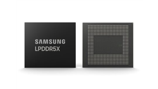
DDR5 PMICs Enable Smarter, Power-Efficient Memory Modules

Power management has received increasing focus in microelectronic systems as the need for greater power density, efficiency and precision have grown apace. One of the important ongoing trends in service of these needs has been the move to localizing power delivery. To optimize system power, it’s best to deliver as high a voltage as possible to the endpoint where the power is consumed. Then at the endpoint, that incoming high voltage can be regulated into the lower voltages with higher currents required by the endpoint components.

We saw this same trend play out in the architecting of the DDR5 generation of computer main memory. In planning for DDR5, the industry laid out ambitious goals for memory bandwidth and capacity. Concurrently, the aim was to maintain power within the same envelope as DDR4 on a per module basis. In order to achieve these goals, DDR5 required a smarter DIMM architecture; one that would embed more intelligence in the DIMM and increase its power efficiency. One of the biggest architectural changes of this smarter DIMM architecture was moving power management from the motherboard to an on-module Power Management IC (PMIC) on each DDR5 RDIMM.

In previous DDR generations, the power regulator on the motherboard had to deliver a low voltage at high current across the motherboard, through a connector and then onto the DIMM. As supply voltages were reduced over time (to maintain power levels at higher data rates), it was a growing challenge to maintain the desired voltage level because of IR drop. By implementing a PMIC on the DDR5 RDIMM, the problem with IR drop was essentially eliminated.

In addition, the on-DIMM PMIC allows for very fine-grain control of the voltage levels supplied to the various components on the DIMM. As such, DIMM suppliers can really dial in the best power levels for the performance target of a particular DIMM configuration. On-DIMM PMICs also offered an economic benefit. Power management on the motherboard meant the regulator had to be designed to support a system with fully populated DIMMs. On-DIMM PMICs means only paying for the power management capacity you need to support your specific system memory configuration.

The upshot is that power management has become a major enabler of increasing memory performance. Advancing memory performance has been the mission of Rambus for nearly 35 years. We’re intimate with memory subsystem design on modules, with expertise across many critical enabling technologies, and have demonstrated the disciplines required to successfully develop chips for the challenging module environment with its increased power density, space constraints and complex thermal management challenges.

As part of the development of our DDR5 memory interface chipset, Rambus built a world-class power management team and has now introduced a new family of DDR5 server PMICs. This new server PMIC product family lays the foundation for a roadmap of future power management chips. As AI continues to expand from training to inference, increasing demands on memory performance will extend beyond servers to client systems and drive the need for new PMIC solutions tailored for emerging use cases and form factors across the computing landscape.

Resources:

The post DDR5 PMICs Enable Smarter, Power-Efficient Memory Modules appeared first on Semiconductor Engineering.

Ctrl-Alt-Speech: Do You Really Want The Government In Your DMs?

Ctrl-Alt-Speech is a weekly podcast about the latest news in online speech, from Mike Masnick and Everything in Moderation‘s Ben Whitelaw.

Subscribe now on Apple Podcasts, Overcast, Spotify, Pocket Casts, YouTube, or your podcast app of choice — or go straight to the RSS feed.

In this week’s round-up of the latest news in online speech, content moderation and internet regulation, Mike and Ben cover:

This episode is brought to you with financial support from the Future of Online Trust & Safety Fund.

Compact Mode continues evolving in the Xbox App on PC

Od: Jon

Jump back in comes to Compact Mode 

In November, we introduced Compact Mode, a feature available via the Xbox app on PC that enhances your gaming experience by providing a more intuitive user interface on smaller screens, including Windows handhelds. We’re excited to announce that the Jump back in feature and enhancements to the Friends panel are rolling out to all Xbox Insiders enrolled in the PC Gaming Preview starting today! 

When we launched Compact Mode, we focused on giving you more space to browse content by simplifying the sidebar. We are now taking it further with Jump back in, our latest feature that allows you to quickly access the games you have recently played on your Windows device when you are immersed in Compact Mode. 

Jump back in will feature the last nine games you played from the app. When you click on any game card, you will go directly to its game hub where you can jump into game play. You can also right-click or press the menu button on your controller to launch directly into game play from the context menu.  

Enhancements to the Friends panel 

With Compact Mode, we have also made it easier to access the Friends panel via controller navigation, with quick access directly from the sidebar, and consistent with other panels like Notifications. We are looking forward to hearing your feedback as we continue to improve the experiences related to Friends in the app. 

Starting next week, a new survey will be available in the Xbox Insider Hub (open or install clicking here) for players enrolled in the PC Gaming preview to give us your feedback on Jump back in and the updated Friends panel access with Compact Mode. As a reminder, you can always give us suggestions for the app or leave feedback by clicking on your Profile card inside the Xbox App and then selecting Feedback from the dropdown menu. We can’t wait to hear from you as we work to bring more enhancements to Compact Mode and the Xbox App on PC for you to enjoy seamless Xbox gaming experiences across all your Windows devices. 

How to get Xbox Insider support and share your feedback 

If you’re an Xbox Insider looking for support, please join our community on the Xbox Insider subreddit. Official Xbox staff, moderators, and fellow Xbox Insiders are there to help. We always recommend adding to threads with the same issue before posting a brand new one. This helps us support you the best we can! Also, you can provide direct feedback to Team Xbox by following the steps here under the “Report a problem online” section. For more information on the Xbox Insider Program, follow us on Twitter at @XboxInsider. Keep an eye on future Xbox Insider Release Notes for more information regarding the PC Gaming Preview

Like what you see but not an Xbox Insider? 

If you’d like to help create the future of Xbox and get early access to new features, join the Xbox Insider Program today by downloading the Xbox Insider Hub for Xbox Series X|S & Xbox One or Windows PC. (Note: The features outlined in this article are currently only available for PC-based Xbox Insiders.) 

The post Compact Mode continues evolving in the Xbox App on PC appeared first on Xbox Wire.

Instagram's terrifying false positive nearly ruined a tech writer's life

instagram account ban

Earlier this week, tech writer and Google Ventures general partner M.G. Siegler received a late-night notification from Meta informing him that his accounts on Instagram, Threads, and Facebook had been suspended for a horrifying alleged violation that he refuses to even name. — Read the rest

The post Instagram's terrifying false positive nearly ruined a tech writer's life appeared first on Boing Boing.

SRAM Security Concerns Grow

SRAM security concerns are intensifying as a combination of new and existing techniques allow hackers to tap into data for longer periods of time after a device is powered down.

This is particularly alarming as the leading edge of design shifts from planar SoCs to heterogeneous systems in package, such as those used in AI or edge processing, where chiplets frequently have their own memory hierarchy. Until now, most cybersecurity concerns involving volatile memory have focused on DRAM, because it is often external and easier to attack. SRAM, in contrast, does not contain a component as obviously vulnerable as a heat-sensitive capacitor, and in the past it has been harder to pinpoint. But as SoCs are disaggregated and more features are added into devices, SRAM is becoming a much bigger security concern.

The attack scheme is well understood. Known as cold boot, it was first identified in 2008, and is essentially a variant of a side-channel attack. In a cold boot approach, an attacker dumps data from internal SRAM to an external device, and then restarts the system from the external device with some code modification. “Cold boot is primarily targeted at SRAM, with the two primary defenses being isolation and in-memory encryption,” said Vijay Seshadri, distinguished engineer at Cycuity.

Compared with network-based attacks, such as DRAM’s rowhammer, cold boot is relatively simple. It relies on physical proximity and a can of compressed air.

The vulnerability was first described by Edward Felton, director of Princeton University’s Center for Information Technology Policy, J. Alex Halderman, currently director of the Center for Computer Security & Society at the University of Michigan, and colleagues. The breakthrough in their research was based on the growing realization in the engineering research community that data does not vanish from memory the moment a device is turned off, which until then was a common assumption. Instead, data in both DRAM and SRAM has a brief “remanence.”[1]

Using a cold boot approach, data can be retrieved, especially if an attacker sprays the chip with compressed air, cooling it enough to slow the degradation of the data. As the researchers described their approach, “We obtained surface temperatures of approximately −50°C with a simple cooling technique — discharging inverted cans of ‘canned air’ duster spray directly onto the chips. At these temperatures, we typically found that fewer than 1% of bits decayed even after 10 minutes without power.”

Unfortunately, despite nearly 20 years of security research since the publication of the Halderman paper, the authors’ warning still holds true. “Though we discuss several strategies for mitigating these risks, we know of no simple remedy that would eliminate them.”

However unrealistic, there is one simple and obvious remedy to cold boot — never leave a device unattended. But given human behavior, it’s safer to assume that every device is vulnerable, from smart watches to servers, as well as automotive chips used for increasingly autonomous driving.

While the original research exclusively examined DRAM, within the last six years cold boot has proven to be one of the most serious vulnerabilities for SRAM. In 2018, researchers at Germany’s Technische Universität Darmstadt published a paper describing a cold boot attack method that is highly resistant to memory erasure techniques, and which can be used to manipulate the cryptographic keys produced by the SRAM physical unclonable function (PUF).

As with so many security issues, it’s been a cat-and-mouse game between remedies and counter-attacks. And because cold boot takes advantage of slowing down memory degradation, in 2022 Yang-Kyu Choi and colleagues at the Korea Advanced Institute of Science and Technology (KAIST), described a way to undo the slowdown with an ultra-fast data sanitization method that worked within 5 ns, using back bias to control the device parameters of CMOS.

Fig. 1: Asymmetric forward back-biasing scheme for permanent erasing. (a) All the data are reset to 1. (b) All the data are reset to 0. Whether all the data where reset to 1 or 0 is determined by the asymmetric forward back-biasing scheme. Source: KAIST/Creative Commons [2]

Fig. 1: Asymmetric forward back-biasing scheme for permanent erasing. (a) All the data are reset to 1. (b) All the data are reset to 0. Whether all the data where reset to 1 or 0 is determined by the asymmetric forward back-biasing scheme. Source: KAIST/Creative Commons [2]

Their paper, as well as others, have inspired new approaches to combating cold boot attacks.

“To mitigate the risk of unauthorized access from unknown devices, main devices, or servers, check the authenticated code and unique identity of each accessing device,” said Jongsin Yun, memory technologist at Siemens EDA. “SRAM PUF is one of the ways to securely identify each device. SRAM is made of two inverters cross-coupled to each other. Although each inverter is designed to be the same device, normally one part of the inverter has a somewhat stronger NMOS than the other due to inherent random dopant fluctuation. During the initial power-on process, SRAM data will be either data 1 or 0, depending on which side has a stronger device. In other words, the initial data state of the SRAM array at the power on is decided by this unique random process variation and most of the bits maintain this property for life. One can use this unique pattern as a fingerprint of a device. The SRAM PUF data is reconstructed with other coded data to form a cryptographic key. SRAM PUF is a great way to anchor its secure data into hardware. Hackers may use a DFT circuit to access the memory. To avoid insecurely reading the SRAM information through DFT, the security-critical design makes DFT force delete the data as an initial process of TEST mode.”

However, there can be instances where data may be required to be kept in a non-volatile memory (NVM). “Data is considered insecure if the NVM is located outside of the device,” said Yun. “Therefore, secured data needs to be stored within the device with write protection. One-time programmable (OTP) memory or fuses are good storage options to prevent malicious attackers from tampering with the modified information. OTP memory and fuses are used to store cryptographic keys, authentication information, and other critical settings for operation within the device. It is useful for anti-rollback, which prevents hackers from exploiting old vulnerabilities that have been fixed in newer versions.”

Chiplet vulnerabilities
Chiplets also could present another vector for attack, due to their complexity and interconnections. “A chiplet has memory, so it’s going to be attacked,” said Cycuity’s Seshadri. “Chiplets, in general, are going to exacerbate the problem, rather than keeping it status quo, because you’re going to have one chiplet talking to another. Could an attack on one chiplet have a side effect on another? There need to be standards to address this. In fact, they’re coming into play already. A chiplet provider has to say, ‘Here’s what I’ve done for security. Here’s what needs to be done when interfacing with another chiplet.”

Yun notes there is a further physical vulnerability for those working with chiplets and SiPs. “When multiple chiplets are connected to form a SiP, we have to trust data coming from an external chip, which creates further complications. Verification of the chiplet’s authenticity becomes very important for SiPs, as there is a risk of malicious counterfeit chiplets being connected to the package for hacking purposes. Detection of such counterfeit chiplets is imperative.”

These precautions also apply when working with DRAM. In all situations, Seshardi said, thinking about security has to go beyond device-level protection. “The onus of protecting DRAM is not just on the DRAM designer or the memory designer,” he said. “It has to be secured by design principles when you are developing. In addition, you have to look at this holistically and do it at a system level. You must consider all the other things that communicate with DRAM or that are placed near DRAM. You must look at a holistic solution, all the way from software down to things like the memory controller and then finally, the DRAM itself.”

Encryption as a backup
Data itself always must be encrypted as second layer of protection against known and novel attacks, so an organization’s assets will still be protected even if someone breaks in via cold boot or another method.

“The first and primary method of preventing a cold boot attack is limiting physical access to the systems, or physically modifying the systems case or hardware preventing an attacker’s access,” said Jim Montgomery, market development director, semiconductor at TXOne Networks. “The most effective programmatic defense against an attack is to ensure encryption of memory using either a hardware- or software-based approach. Utilizing memory encryption will ensure that regardless of trying to dump the memory, or physically removing the memory, the encryption keys will remain secure.”

Montgomery also points out that TXOne is working with the Semiconductor Manufacturing Cybersecurity Consortium (SMCC) to develop common criteria based upon SEMI E187 and E188 standards to assist DM’s and OEM’s to implement secure procedures for systems security and integrity, including controlling the physical environment.

What kind and how much encryption will depend on use cases, said Jun Kawaguchi, global marketing executive for Winbond. “Encryption strength for a traffic signal controller is going to be different from encryption for nuclear plants or medical devices, critical applications where you need much higher levels,” he said. “There are different strengths and costs to it.”

Another problem, in the post-quantum era, is that encryption itself may be vulnerable. To defend against those possibilities, researchers are developing post-quantum encryption schemes. One way to stay a step ahead is homomorphic encryption [HE], which will find a role in data sharing, since computations can be performed on encrypted data without first having to decrypt it.

Homomorphic encryption could be in widespread use as soon as the next few years, according to Ronen Levy, senior manager for IBM’s Cloud Security & Privacy Technologies Department, and Omri Soceanu, AI Security Group manager at IBM.  However, there are still challenges to be overcome.

“There are three main inhibitors for widespread adoption of homomorphic encryption — performance, consumability, and standardization,” according to Levy. “The main inhibitor, by far, is performance. Homomorphic encryption comes with some latency and storage overheads. FHE hardware acceleration will be critical to solving these issues, as well as algorithmic and cryptographic solutions, but without the necessary expertise it can be quite challenging.”

An additional issue is that most consumers of HE technology, such as data scientists and application developers, do not possess deep cryptographic skills, HE solutions that are designed for cryptographers can be impractical. A few HE solutions require algorithmic and cryptographic expertise that inhibit adoption by those who lack these skills.

Finally, there is a lack of standardization. “Homomorphic encryption is in the process of being standardized,” said Soceanu. “But until it is fully standardized, large organizations may be hesitant to adopt a cryptographic solution that has not been approved by standardization bodies.”

Once these issues are resolved, they predicted widespread use as soon as the next few years. “Performance is already practical for a variety of use cases, and as hardware solutions for homomorphic encryption become a reality, more use cases would become practical,” said Levy. “Consumability is addressed by creating more solutions, making it easier and hopefully as frictionless as possible to move analytics to homomorphic encryption. Additionally, standardization efforts are already in progress.”

A new attack and an old problem
Unfortunately, security never will be as simple as making users more aware of their surroundings. Otherwise, cold boot could be completely eliminated as a threat. Instead, it’s essential to keep up with conference talks and the published literature, as graduate students keep probing SRAM for vulnerabilities, hopefully one step ahead of genuine attackers.

For example, SRAM-related cold boot attacks originally targeted discrete SRAM. The reason is that it’s far more complicated to attack on-chip SRAM, which is isolated from external probing and has minimal intrinsic capacitance. However, in 2022, Jubayer Mahmod, then a graduate student at Virginia Tech and his advisor, associate professor Matthew Hicks, demonstrated what they dubbed “Volt Boot,” a new method that could penetrate on-chip SRAM. According to their paper, “Volt Boot leverages asymmetrical power states (e.g., on vs. off) to force SRAM state retention across power cycles, eliminating the need for traditional cold boot attack enablers, such as low-temperature or intrinsic data retention time…Unlike other forms of SRAM data retention attacks, Volt Boot retrieves data with 100% accuracy — without any complex post-processing.”

Conclusion
While scientists and engineers continue to identify vulnerabilities and develop security solutions, decisions about how much security to include in a design is an economic one. Cost vs. risk is a complex formula that depends on the end application, the impact of a breach, and the likelihood that an attack will occur.

“It’s like insurance,” said Kawaguchi. “Security engineers and people like us who are trying to promote security solutions get frustrated because, similar to insurance pitches, people respond with skepticism. ‘Why would I need it? That problem has never happened before.’ Engineers have a hard time convincing their managers to spend that extra dollar on the costs because of this ‘it-never-happened-before’ attitude. In the end, there are compromises. Yet ultimately, it’s going to cost manufacturers a lot of money when suddenly there’s a deluge of demands to fix this situation right away.”

References

  1. S. Skorobogatov, “Low temperature data remanence in static RAM”, Technical report UCAM-CL-TR-536, University of Cambridge Computer Laboratory, June 2002.
  2. Han, SJ., Han, JK., Yun, GJ. et al. Ultra-fast data sanitization of SRAM by back-biasing to resist a cold boot attack. Sci Rep 12, 35 (2022). https://doi.org/10.1038/s41598-021-03994-2

The post SRAM Security Concerns Grow appeared first on Semiconductor Engineering.
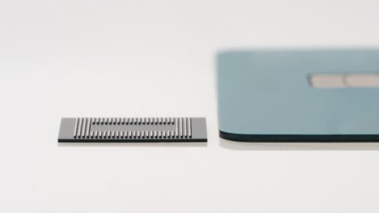
Crucial’s LPCAMM2 LPDDR5X memory modules are now available for purchase

In recent years PC makers had two choices when it came to laptop memory. They could include SODIMM slots with support for user-replaceable DDR memory or LPDDR memory which typically uses less power and takes up less space, effectively trading repairability and upgradeability for longer battery life and/or more compact designs. Now LPCAMM2 has arrived […]

The post Crucial’s LPCAMM2 LPDDR5X memory modules are now available for purchase appeared first on Liliputing.

Samsung Unveils 10.7Gbps LPDDR5X Memory - The Fastest Yet

Samsung today has announced that they have developed an even faster generation of LPDDR5X memory that is set to top out at LPDDR5X-10700 speeds. The updated memory is slated to offer 25% better performance and 30% greater capacity compared to existing mobile DRAM devices from the company. The new chips also appear to be tangibly faster than Micron's LPDDR5X memory and SK hynix's LPDDR5T chips.

Samsung's forthcoming LPDDR5X devices feature a data transfer rate of 10.7 GT/s as well as maximum capacity per stack of 32 GB. This allows Samsung's clients to equip their latest smartphones or laptops with 32 GB of low-power memory using just one DRAM package, which greatly simplifies their designs. Samsung says that 32 GB of memory will be particularly beneficial for on-device AI applications.

Samsung is using its latest-generation 12nm-class DRAM process technology to make its LPDDR5X-10700 devices, which allows the company to achieve the smallest LPDDR device size in the industry, the memory maker said.

In terms of power efficiency, Samsung claims that they have integrated multiple new power-saving features into the new LPDDR5X devices. These include an optimized power variation system that adjusts energy consumption based on workload, and expanded intervals for low-power mode that extend the periods of energy saving. These innovations collectively enhance power efficiency by 25% compared to earlier versions, benefiting mobile platforms by extending battery life, the company said.

“As demand for low-power, high-performance memory increases, LPDDR DRAM is expected to expand its applications from mainly mobile to other areas that traditionally require higher performance and reliability such as PCs, accelerators, servers and automobiles,” said YongCheol Bae, Executive Vice President of Memory Product Planning of the Memory Business at Samsung Electronics. “Samsung will continue to innovate and deliver optimized products for the upcoming on-device AI era through close collaboration with customers.”

Samsung plans to initiate mass production of the 10.7 GT/s LPDDR5X DRAM in the second half of this year. This follows a series of compatibility tests with mobile application processors and device manufacturers to ensure seamless integration into future products.

Can you turn off Meta AI on Facebook, Instagram, and WhatsApp?

If you’ve recently found yourself staring at unfamiliar buttons and prompts on your favorite Meta apps, you’re not alone. The recent rollout marks the debut of Meta AI’s latest large language model, Llama 3, promising more personalized interactions but also potentially more intrusive AI suggestions. Still, this is the closest it has ever been to ChatGPT.

But what if you’re not ready to embrace the AI revolution? What if you find the integration more cumbersome than helpful? Maybe you hate that the answers are not completely reliable. But is there any way to turn off the new Meta AI integration and regain some semblance of your pre-AI browsing experience?

Instagram: How to change your chat theme

Od: Anu Joy

Since Instagram is all about visuals, the plain background of your DMs might seem bland. The social media app lets you change the theme to spice things up. You can choose from various patterns and colors that match your aesthetic and customize the appearance of your messages based on who youre chatting with. This guide shows you how to change your Instagram theme on a budget Android phone, a flagship device, or an iPhone.

Stay awhile and play this free Diablo-inspired indie as the mayor of Tristram

Mayors in RPG games are rarely given the spotlight. They're mostly just there to give you an early quest involving goat banditry or windmill rats or some such other domestic drudgery. Or, in the case of Tristram’s mayor in Diablo, to fret behind the scenes about how to properly fit considerable cathedral repairs into this month’s budget. Well, no more must this valuable civil servant hide behind balance sheets, occasionally popping out to cut a big ribbon in celebration of a nearby mausoleum being turned into a Wetherspoons. Tristam is a 72 hour Ludum Dare project where you play as said town’s mayor. And this time: It’s ceremonial!

Read more

Samsung Unveils 10.7Gbps LPDDR5X Memory - The Fastest Yet

Samsung today has announced that they have developed an even faster generation of LPDDR5X memory that is set to top out at LPDDR5X-10700 speeds. The updated memory is slated to offer 25% better performance and 30% greater capacity compared to existing mobile DRAM devices from the company. The new chips also appear to be tangibly faster than Micron's LPDDR5X memory and SK hynix's LPDDR5T chips.

Samsung's forthcoming LPDDR5X devices feature a data transfer rate of 10.7 GT/s as well as maximum capacity per stack of 32 GB. This allows Samsung's clients to equip their latest smartphones or laptops with 32 GB of low-power memory using just one DRAM package, which greatly simplifies their designs. Samsung says that 32 GB of memory will be particularly beneficial for on-device AI applications.

Samsung is using its latest-generation 12nm-class DRAM process technology to make its LPDDR5X-10700 devices, which allows the company to achieve the smallest LPDDR device size in the industry, the memory maker said.

In terms of power efficiency, Samsung claims that they have integrated multiple new power-saving features into the new LPDDR5X devices. These include an optimized power variation system that adjusts energy consumption based on workload, and expanded intervals for low-power mode that extend the periods of energy saving. These innovations collectively enhance power efficiency by 25% compared to earlier versions, benefiting mobile platforms by extending battery life, the company said.

“As demand for low-power, high-performance memory increases, LPDDR DRAM is expected to expand its applications from mainly mobile to other areas that traditionally require higher performance and reliability such as PCs, accelerators, servers and automobiles,” said YongCheol Bae, Executive Vice President of Memory Product Planning of the Memory Business at Samsung Electronics. “Samsung will continue to innovate and deliver optimized products for the upcoming on-device AI era through close collaboration with customers.”

Samsung plans to initiate mass production of the 10.7 GT/s LPDDR5X DRAM in the second half of this year. This follows a series of compatibility tests with mobile application processors and device manufacturers to ensure seamless integration into future products.

SK hynix to Build $3.87 Billion Memory Packaging Fab in the U.S. for HBM4 and Beyond

SK hynix this week announced plans to build its advanced memory packaging facility in West Lafayette, Indiana. The move can be considered as a milestone both for the memory maker and the U.S., as this is the first advanced memory packaging facility in the country and the company's first significant manufacturing operation in America. The facility will be used to build next-generation types of high-bandwidth memory (HBM) stacks when it begins operations in 2028. Also, SK hynix agreed to work on R&D projects with Purdue University.

"We are excited to become the first in the industry to build a state-of-the-art advanced packaging facility for AI products in the United States that will help strengthen supply-chain resilience and develop a local semiconductor ecosystem," said SK hynix CEO Kwak Noh-Jung.

One of The Most Advanced Chip Packaging Facility Ever

The facility will handle assembly of HBM known good stacked dies (KGSDs), which consist of multiple memory devices stacked on a base die. Furthermore, it will be used to develop next-generations of HBM and will therefore house a packaging R&D line. However, the plant will not make DRAM dies themselves, and will likely source them from SK hynix's fabs in South Korea.

The plant will require SK hynix to invest $3.87 billion, which will make it one of the most advanced semiconductor packaging facilities in the world. Meanwhile, SK hynix held the investment agreement ceremony with representatives from Indiana State, Purdue University, and the U.S. government, which indicates parties financially involved in the project, but this week's event did not disclose whether SK hynix will receive any money from the U.S. government under the CHIPS Act or other funding initiatives.

The cost of the facility significantly exceeds that of packaging facilities built by other major players in the industry, such as ASE Group, Intel, and TSMC, which highlights how significant of an investment this is for SK hnix. In fact, $3.87 billion higher than advanced packaging CapEx budgets of Intel, TSMC and Samsung in 2023, based on estimates from Yole Intelligence.

Given that the fab comes online in 2028, based on SK hynix's product roadmap we'd expect that it will be used at least in part to assemble HBM4 and HBM4E stacks. Notably, since HBM4 and HBM4E stacks are set to feature a 2048-bit interface, their packaging process will be considerably more complex than the existing 1024-bit HBM3/HBM3E packaging and will require usage of more advanced tools, which is why it is poised to be more expensive than some existing advanced packaging facilities. Due to the extremely complex 2048-bit interface, many chip designers who are going to use HBM4/HBM4E are expected to integrate it directly onto their processors using hybrid bonding and not use silicon interposers. Unfortunately, it is unclear whether the SK hynix facility will be able to offer such service.

HBM is mainly used for AI and HPC applications, so it is strategically important to have its production in the U.S. Meanwhile, actual memory dies will still need to be made elsewhere, at dedicated DRAM fabs.

Purdue University Collaboration

In addition to support set to be provided by state and local governmens, SK hynix chose to establish its new facility in West Lafayette, Indiana, to collaborate with Purdue University as well as with Purdue's Birck Nanotechnology Center on R&D projects, which includes advanced packaging and heterogeneous integration.

SK hynix intends to work in partnership with Purdue University and Ivy Tech Community College to create training programs and multidisciplinary degree courses aimed at nurturing a skilled workforce and establishing a consistent stream of emerging talent for its advanced memory packaging facility and R&D operations.

"SK hynix is the global pioneer and dominant market leader in memory chips for AI," Purdue University President Mung Chiang said. "This transformational investment reflects our state and university's tremendous strength in semiconductors, hardware AI, and hard tech corridor. It is also a monumental moment for completing the supply chain of digital economy in our country through chips advanced packaging. Located at Purdue Research Park, the largest facility of its kind at a U.S. university will grow and succeed through innovation."

Meta’s supercharged AI assistant is taking over its apps across the world

Meta logo on smartphone stock photo (13)

Credit: Edgar Cervantes / Android Authority

  • Meta has dramatically upgraded its AI assistant, powered by the new Llama 3 language model.
  • The enhanced Meta AI is available on Facebook, Instagram, WhatsApp, Messenger, and its new standalone website.
  • Meta also announced the rollout of an upgraded image generator, where images change in real-time as you type text descriptions.


The battle for AI supremacy between ChatGPT and Gemini just turned into a three-way race as Meta has unveiled a significantly upgraded version of its AI assistant. The new-and-improved Meta AI, powered by the cutting-edge Llama 3 language model, is boldly proclaimed by CEO Mark Zuckerberg to be “now the most intelligent AI assistant that you can freely use.”

Meta first introduced Meta AI last year, but it was limited to the US, and its capabilities were not on par with those of competitors like ChatGPT and Gemini. However, the integration of the Llama 3 model, also announced today, represents a seemingly quantum leap for Meta’s AI. Benchmark tests conducted by the company indicate that, with Llama 3 at its core, Meta AI has the potential to outperform other top-tier AI models, particularly in areas like translation, dialogue generation, and complex reasoning.

What can the new Meta AI do?

The overhauled Meta AI is now directly accessible through the search bars within Facebook, Instagram (DMs page), WhatsApp, and Messenger. Plus, you can access it at a new standalone website, meta.ai. It can search the web for you, provide recommendations for restaurants, flights, and more, or clarify complex concepts. On Facebook, Meta AI can also interact with your feed, allowing you to ask questions about content you see, like the best time to catch the Northern Lights after viewing a stunning photo of them.

I could even ask it for tailored content like fitness reels or comedy videos, with Meta AI curating a 5-video feed for me in those cases. Meta has included many prompts under the search bar on Facebook and Instagram to help us get the most out of Meta AI’s abilities. Thankfully, we can still use the search bars for regular searches for accounts and hashtags.

From what I could see so far, Meta AI’s answers are not as nuanced and detailed as what Gemini would give me for similar questions, but it could benefit from two key strengths. First, it’s seamlessly embedded within Meta’s popular apps — Facebook, Instagram, WhatsApp, and Messenger — giving their billions of users convenient access to the AI assistant. Secondly, Meta AI isn’t tied to one search engine; it openly uses both Google and Bing to process queries, removing potential bias toward either company’s algorithms.

One of the most intriguing parts of Meta AI is its Imagine image generator. This feature first appeared within WhatsApp a few months ago and allowed users to create AI-generated images based on text descriptions. Since then, it has expanded to Instagram and Facebook.

Starting today, WhatsApp beta users and those using Meta AI’s desktop website in the US can try out an even more advanced version of Imagine. This version generates images in real-time while you type, with the image updating as you add more details, really demonstrating how far generative AI has come.

Currently, Meta AI works in English and is rolling out to many countries outside the US, including Australia, Canada, Ghana, Jamaica, Malawi, New Zealand, Nigeria, Pakistan, Singapore, South Africa, Uganda, Zambia, and Zimbabwe, with more on the way.

The classic Pepper's Ghost illusion, with a Peep marshmallow

Od: Popkin

This incredible Pepper's Ghost illusion includes a musical Peep marshmallow. If you aren't familiar with the technique, a Pepper's Ghost illusion is a 3D floating hologram that you can build yourself at home.

The Pepper's Ghost in this video takes things to the next level, as it's interactive and wired so that it morphs and changes shape when a keyboard is played. — Read the rest

The post The classic Pepper's Ghost illusion, with a Peep marshmallow appeared first on Boing Boing.

Exploring Process Scenarios To Improve DRAM Device Performance

In the world of advanced semiconductor fabrication, creating precise device profiles (edge shapes) is an important step in achieving targeted on-chip electrical performance. For example, saddle fin profiles in a DRAM memory device must be precisely fabricated during process development in order to avoid memory performance issues. Saddle fins were introduced in DRAM devices to increase channel length, prevent short channel effects, and increase data retention times. Critical process equipment settings like etch selectivity, or the gas ratio of the etch process, can significantly impact the shape of fabricated saddle fin profiles. These process and profile changes have significant impact on DRAM device performance. It can be challenging to explore all possible saddle fin profile combinations using traditional silicon testing, since wafer-based testing is time-consuming and expensive. To address this issue, virtual fabrication software (SEMulator3D) can be used to test different saddle fin profile shapes without the time and cost of wafer-based development. In this article, we will review an example of using virtual fabrication for DRAM saddle fin profile development. We will also assess DRAM device performance under different saddle fin profile conditions. This methodology can be used to guide process and integration teams in the development of process recipes and specifications for DRAM devices.

The challenge of exploring different profiles

Imagine that you are a DRAM process engineer, and have received nominal process conditions, device specifications and a target saddle fin profile for a new DRAM design. You would like to explore some different process options and saddle fin profiles to improve the performance of your DRAM device. What should you do? This is a common situation for integration and process engineers during the early R&D stages of DRAM process development.

Traditional methods of exploring saddle fin profiles are difficult and sometimes impractical. These methods involve the creation of a series of unique saddle fin profiles on silicon wafers. The process is time-consuming, expensive, and in many cases impractical, due to the large number of scenarios that must be tested.

One solution to these challenges is to use virtual fabrication. SEMulator3D allows us to create and analyze saddle fin profiles within a virtual environment and to subsequently extract and compare device characteristics of these different profiles. The strength of this approach is its ability to accurately simulate the real-world performance of these devices, but to do so faster and less-expensively than using wafer-based testing.

Methodology

Let’s dive into the methodology behind our approach:

Creating saddle fin profiles in a virtual environment

First, we input the design data and process flow (or process steps) for our device in SEMulator3D. The software can then generate a “virtual” 3D DRAM structure and provide a visualization of saddle fin profiles (figure 1). In figure 1(a), a full 3D DRAM structure including the entire simulation domain is displayed. To enable detailed device study, we have cropped a small portion of the simulation domain from this large 3D area. In figure 1(b), we have extracted a cross sectional view of the saddle fin structure, which can be modified by varying a set of multi-etch steps in the process model. The section of the saddle fin that we would like to modify is identified as the “AA” (active area). We can finely tune the etch taper angle, AA/fin CD, fin height, taper angle and additional nominal device parameters to modify the AA profile.

Figure 1: Process flow set up by SEMulator3D containing 3 figures marked A,B and C. Figure A contains a 3D simulated DRAM structure, with metals, nitrides, oxides and silicon structures shown in different colors. Figure B contains a cross section view of the saddle fin, with the bitline, active area, CC and wordline areas highlighted in the figure. Figure C highlights the key specifications of the saddle fin profile that can will be changed during simulation, including the etch taper angle, AA/fin CD, fin height, and taper angle to modify the saddle fin profile and shape.

Fig. 1: Process flow set up by SEMulator3D: (a) DRAM structure and (b) Cross section view of saddle fin along with key specifications of the saddle fin profile.

Using the structures that we have built in SEMulator3D, we can next assign dopants and ports to the simulated structure and perform electrical performance evaluation. Accurately assigning dopant species, and defining dopant concentrations within the structure, is critical to ensuring the accuracy of our simulation. In figure 2(a), we display a dopant concentration distribution generated in SEMulator3D.

Ports are contact points in the model which are used to apply or extract electrical signals during a device study. Proper assignment of the ports is very important. Figure 2(b) provides an example of port assignment in our test DRAM structure. By accurately assigning the ports and dopants, we can extract the device’s electrical characteristics under different process scenarios.

Figure 2: Dopant concentration and Port Setup for the DRAM device, marked at Figures 2A and 2B. In Figure 2(a), we display a dopant concentration distribution generated in SEMulator3D. The highest dopant concentration is found in the center of the device, shown in red and yellow. Figure 2(b) provides an example of port assignment in our test DRAM structure, with assignments shown against a device cross-section. Ports are assigned at the drain, source and gate of the device.

Fig. 2: (a) Dopant concentration and (b) Port assignments (in blue).

Manufacturability validation

It is important to ensure that our simulation models match real world results. We can validate our model against cross-sectional images (SEM or TEM images) from an actual fabricated device. To ensure that our simulated device matches the behavior of an actual manufactured chip, we can create real silicon test wafers containing DRAM structures with different saddle fin profiles. To study different saddle fin profiles, we will use different etch recipes on an etch machine to vary the DRAM wordline etch step. This allows us to create specific saddle fin profiles in silicon that can be compared to our simulated profiles. A process engineer can change etch recipes and easily create silicon-based etch profiles that match simulated cross section images, as shown in figure 3. In this case, the engineer created a nominal (Process of Record) profile, a “round” profile (with a rounded top), and a triangular shaped profile (with a triangular top). This wafer-based data is not only used to test electrical performance of the DRAM under different saddle fin profile conditions, but can also be fed back into the virtual model to calibrate the model and ensure that it is accurate during future use.

Figure 3: Cross section TEM/SEM images of saddle fin profiles taken from actual silicon devices are displayed, compared to the predicted model results from SEMulator3D. 3 side-by-side TEM images are shown for the saddle fin profiles vs. the model results, for : (a) Nominal condition (Process of Record), (b) Round profile and (c) Triangle profile

Fig. 3: Cross section images vs. models: (a) Nominal condition (Process of Record), (b) Round profile and (c) Triangle profile.

Device simulation and validation

In the final stage of our study, we will review the electrical simulation results for different saddle fin profile shapes. Figure 4 displays simulated electrical performance results for the round profile and triangular saddle fin profile. For each of the two profiles, the value of the transistor Subthreshold Swing (SS), On Current (Ion), and Threshold Voltage (Vt) are displayed, with the differences shown. Process integration engineers can use this type of simulation to compare device performance using different process approaches. The same electrical performance differences (trend) were seen on actual fabricated devices, validating the accuracy and reliability of our simulation approach.

Figure 4: Simulated electrical performance results for the round profile and triangular saddle fin profile. For each of the two profiles, the value of the transistor Subthreshold Swing (SS), On Current (Ion), and Threshold Voltage (Vt) are displayed, with the differences shown.

Fig. 4: Device electrical simulation results: the transistor performance difference between the Round and Triangular Saddle Fin profile is shown for Subthreshold Swing (SS), On Current (Ion) and Threshold Voltage (Vt).

Conclusions

SEMulator3D provides numerous benefits for the semiconductor manufacturing industry. It allows process integration teams to understand device performance under different process scenarios, and lets them easily explore new processes and architectural opportunities. In this article, we reviewed an example of how virtual fabrication can be used to assess DRAM device performance under different saddle fin profile conditions. Figure 5 displays a summary of the virtual fabrication process, and how we used it to understand, optimize and validate different process scenarios.

Figure 5: A summary of the virtual fabrication process undertaken in this study, including model setup, followed by an exploration of process conditions, followed by electrical analysis and final silicon verification. This process is circular, with the ability to repeat the loop as new information is collected.

Fig. 5: Summary of virtual fabrication process.

Virtual fabrication can be used to guide process and integration teams in the development of process recipes and specifications for any new memory or logic device, and to do so at greater speed and lower cost than silicon-based experimentation.

The post Exploring Process Scenarios To Improve DRAM Device Performance appeared first on Semiconductor Engineering.

Best RAM for Intel Core i5-14600K in 2024

To make the most of the Intel Core i5-14600K, either the best DDR4 or DDR5 RAM will need to be used. System memory is used by the processor to store data for quicker access as these modules are capable of much higher bandwidth than mechanical hard drives or even the fastest M.2 NVMe solid-state drives. The more memory available, the more data the PC will be able to store before having to resort to slower storage drives. For the Core i5-14600K, I'd recommend 32GB as a healthy amount for a new PC.

Samsung Unveils 10.7Gbps LPDDR5X Memory - The Fastest Yet

Samsung today has announced that they have developed an even faster generation of LPDDR5X memory that is set to top out at LPDDR5X-10700 speeds. The updated memory is slated to offer 25% better performance and 30% greater capacity compared to existing mobile DRAM devices from the company. The new chips also appear to be tangibly faster than Micron's LPDDR5X memory and SK hynix's LPDDR5T chips.

Samsung's forthcoming LPDDR5X devices feature a data transfer rate of 10.7 GT/s as well as maximum capacity per stack of 32 GB. This allows Samsung's clients to equip their latest smartphones or laptops with 32 GB of low-power memory using just one DRAM package, which greatly simplifies their designs. Samsung says that 32 GB of memory will be particularly beneficial for on-device AI applications.

Samsung is using its latest-generation 12nm-class DRAM process technology to make its LPDDR5X-10700 devices, which allows the company to achieve the smallest LPDDR device size in the industry, the memory maker said.

In terms of power efficiency, Samsung claims that they have integrated multiple new power-saving features into the new LPDDR5X devices. These include an optimized power variation system that adjusts energy consumption based on workload, and expanded intervals for low-power mode that extend the periods of energy saving. These innovations collectively enhance power efficiency by 25% compared to earlier versions, benefiting mobile platforms by extending battery life, the company said.

“As demand for low-power, high-performance memory increases, LPDDR DRAM is expected to expand its applications from mainly mobile to other areas that traditionally require higher performance and reliability such as PCs, accelerators, servers and automobiles,” said YongCheol Bae, Executive Vice President of Memory Product Planning of the Memory Business at Samsung Electronics. “Samsung will continue to innovate and deliver optimized products for the upcoming on-device AI era through close collaboration with customers.”

Samsung plans to initiate mass production of the 10.7 GT/s LPDDR5X DRAM in the second half of this year. This follows a series of compatibility tests with mobile application processors and device manufacturers to ensure seamless integration into future products.

SK hynix to Build $3.87 Billion Memory Packaging Fab in the U.S. for HBM4 and Beyond

SK hynix this week announced plans to build its advanced memory packaging facility in West Lafayette, Indiana. The move can be considered as a milestone both for the memory maker and the U.S., as this is the first advanced memory packaging facility in the country and the company's first significant manufacturing operation in America. The facility will be used to build next-generation types of high-bandwidth memory (HBM) stacks when it begins operations in 2028. Also, SK hynix agreed to work on R&D projects with Purdue University.

"We are excited to become the first in the industry to build a state-of-the-art advanced packaging facility for AI products in the United States that will help strengthen supply-chain resilience and develop a local semiconductor ecosystem," said SK hynix CEO Kwak Noh-Jung.

One of The Most Advanced Chip Packaging Facility Ever

The facility will handle assembly of HBM known good stacked dies (KGSDs), which consist of multiple memory devices stacked on a base die. Furthermore, it will be used to develop next-generations of HBM and will therefore house a packaging R&D line. However, the plant will not make DRAM dies themselves, and will likely source them from SK hynix's fabs in South Korea.

The plant will require SK hynix to invest $3.87 billion, which will make it one of the most advanced semiconductor packaging facilities in the world. Meanwhile, SK hynix held the investment agreement ceremony with representatives from Indiana State, Purdue University, and the U.S. government, which indicates parties financially involved in the project, but this week's event did not disclose whether SK hynix will receive any money from the U.S. government under the CHIPS Act or other funding initiatives.

The cost of the facility significantly exceeds that of packaging facilities built by other major players in the industry, such as ASE Group, Intel, and TSMC, which highlights how significant of an investment this is for SK hnix. In fact, $3.87 billion higher than advanced packaging CapEx budgets of Intel, TSMC and Samsung in 2023, based on estimates from Yole Intelligence.

Given that the fab comes online in 2028, based on SK hynix's product roadmap we'd expect that it will be used at least in part to assemble HBM4 and HBM4E stacks. Notably, since HBM4 and HBM4E stacks are set to feature a 2048-bit interface, their packaging process will be considerably more complex than the existing 1024-bit HBM3/HBM3E packaging and will require usage of more advanced tools, which is why it is poised to be more expensive than some existing advanced packaging facilities. Due to the extremely complex 2048-bit interface, many chip designers who are going to use HBM4/HBM4E are expected to integrate it directly onto their processors using hybrid bonding and not use silicon interposers. Unfortunately, it is unclear whether the SK hynix facility will be able to offer such service.

HBM is mainly used for AI and HPC applications, so it is strategically important to have its production in the U.S. Meanwhile, actual memory dies will still need to be made elsewhere, at dedicated DRAM fabs.

Purdue University Collaboration

In addition to support set to be provided by state and local governmens, SK hynix chose to establish its new facility in West Lafayette, Indiana, to collaborate with Purdue University as well as with Purdue's Birck Nanotechnology Center on R&D projects, which includes advanced packaging and heterogeneous integration.

SK hynix intends to work in partnership with Purdue University and Ivy Tech Community College to create training programs and multidisciplinary degree courses aimed at nurturing a skilled workforce and establishing a consistent stream of emerging talent for its advanced memory packaging facility and R&D operations.

"SK hynix is the global pioneer and dominant market leader in memory chips for AI," Purdue University President Mung Chiang said. "This transformational investment reflects our state and university's tremendous strength in semiconductors, hardware AI, and hard tech corridor. It is also a monumental moment for completing the supply chain of digital economy in our country through chips advanced packaging. Located at Purdue Research Park, the largest facility of its kind at a U.S. university will grow and succeed through innovation."

Meta’s supercharged AI assistant is taking over its apps across the world

Meta logo on smartphone stock photo (13)

Credit: Edgar Cervantes / Android Authority

  • Meta has dramatically upgraded its AI assistant, powered by the new Llama 3 language model.
  • The enhanced Meta AI is available on Facebook, Instagram, WhatsApp, Messenger, and its new standalone website.
  • Meta also announced the rollout of an upgraded image generator, where images change in real-time as you type text descriptions.


The battle for AI supremacy between ChatGPT and Gemini just turned into a three-way race as Meta has unveiled a significantly upgraded version of its AI assistant. The new-and-improved Meta AI, powered by the cutting-edge Llama 3 language model, is boldly proclaimed by CEO Mark Zuckerberg to be “now the most intelligent AI assistant that you can freely use.”

Meta first introduced Meta AI last year, but it was limited to the US, and its capabilities were not on par with those of competitors like ChatGPT and Gemini. However, the integration of the Llama 3 model, also announced today, represents a seemingly quantum leap for Meta’s AI. Benchmark tests conducted by the company indicate that, with Llama 3 at its core, Meta AI has the potential to outperform other top-tier AI models, particularly in areas like translation, dialogue generation, and complex reasoning.

What can the new Meta AI do?

The overhauled Meta AI is now directly accessible through the search bars within Facebook, Instagram (DMs page), WhatsApp, and Messenger. Plus, you can access it at a new standalone website, meta.ai. It can search the web for you, provide recommendations for restaurants, flights, and more, or clarify complex concepts. On Facebook, Meta AI can also interact with your feed, allowing you to ask questions about content you see, like the best time to catch the Northern Lights after viewing a stunning photo of them.

I could even ask it for tailored content like fitness reels or comedy videos, with Meta AI curating a 5-video feed for me in those cases. Meta has included many prompts under the search bar on Facebook and Instagram to help us get the most out of Meta AI’s abilities. Thankfully, we can still use the search bars for regular searches for accounts and hashtags.

From what I could see so far, Meta AI’s answers are not as nuanced and detailed as what Gemini would give me for similar questions, but it could benefit from two key strengths. First, it’s seamlessly embedded within Meta’s popular apps — Facebook, Instagram, WhatsApp, and Messenger — giving their billions of users convenient access to the AI assistant. Secondly, Meta AI isn’t tied to one search engine; it openly uses both Google and Bing to process queries, removing potential bias toward either company’s algorithms.

One of the most intriguing parts of Meta AI is its Imagine image generator. This feature first appeared within WhatsApp a few months ago and allowed users to create AI-generated images based on text descriptions. Since then, it has expanded to Instagram and Facebook.

Starting today, WhatsApp beta users and those using Meta AI’s desktop website in the US can try out an even more advanced version of Imagine. This version generates images in real-time while you type, with the image updating as you add more details, really demonstrating how far generative AI has come.

Currently, Meta AI works in English and is rolling out to many countries outside the US, including Australia, Canada, Ghana, Jamaica, Malawi, New Zealand, Nigeria, Pakistan, Singapore, South Africa, Uganda, Zambia, and Zimbabwe, with more on the way.

Exploring Process Scenarios To Improve DRAM Device Performance

In the world of advanced semiconductor fabrication, creating precise device profiles (edge shapes) is an important step in achieving targeted on-chip electrical performance. For example, saddle fin profiles in a DRAM memory device must be precisely fabricated during process development in order to avoid memory performance issues. Saddle fins were introduced in DRAM devices to increase channel length, prevent short channel effects, and increase data retention times. Critical process equipment settings like etch selectivity, or the gas ratio of the etch process, can significantly impact the shape of fabricated saddle fin profiles. These process and profile changes have significant impact on DRAM device performance. It can be challenging to explore all possible saddle fin profile combinations using traditional silicon testing, since wafer-based testing is time-consuming and expensive. To address this issue, virtual fabrication software (SEMulator3D) can be used to test different saddle fin profile shapes without the time and cost of wafer-based development. In this article, we will review an example of using virtual fabrication for DRAM saddle fin profile development. We will also assess DRAM device performance under different saddle fin profile conditions. This methodology can be used to guide process and integration teams in the development of process recipes and specifications for DRAM devices.

The challenge of exploring different profiles

Imagine that you are a DRAM process engineer, and have received nominal process conditions, device specifications and a target saddle fin profile for a new DRAM design. You would like to explore some different process options and saddle fin profiles to improve the performance of your DRAM device. What should you do? This is a common situation for integration and process engineers during the early R&D stages of DRAM process development.

Traditional methods of exploring saddle fin profiles are difficult and sometimes impractical. These methods involve the creation of a series of unique saddle fin profiles on silicon wafers. The process is time-consuming, expensive, and in many cases impractical, due to the large number of scenarios that must be tested.

One solution to these challenges is to use virtual fabrication. SEMulator3D allows us to create and analyze saddle fin profiles within a virtual environment and to subsequently extract and compare device characteristics of these different profiles. The strength of this approach is its ability to accurately simulate the real-world performance of these devices, but to do so faster and less-expensively than using wafer-based testing.

Methodology

Let’s dive into the methodology behind our approach:

Creating saddle fin profiles in a virtual environment

First, we input the design data and process flow (or process steps) for our device in SEMulator3D. The software can then generate a “virtual” 3D DRAM structure and provide a visualization of saddle fin profiles (figure 1). In figure 1(a), a full 3D DRAM structure including the entire simulation domain is displayed. To enable detailed device study, we have cropped a small portion of the simulation domain from this large 3D area. In figure 1(b), we have extracted a cross sectional view of the saddle fin structure, which can be modified by varying a set of multi-etch steps in the process model. The section of the saddle fin that we would like to modify is identified as the “AA” (active area). We can finely tune the etch taper angle, AA/fin CD, fin height, taper angle and additional nominal device parameters to modify the AA profile.

Figure 1: Process flow set up by SEMulator3D containing 3 figures marked A,B and C. Figure A contains a 3D simulated DRAM structure, with metals, nitrides, oxides and silicon structures shown in different colors. Figure B contains a cross section view of the saddle fin, with the bitline, active area, CC and wordline areas highlighted in the figure. Figure C highlights the key specifications of the saddle fin profile that can will be changed during simulation, including the etch taper angle, AA/fin CD, fin height, and taper angle to modify the saddle fin profile and shape.

Fig. 1: Process flow set up by SEMulator3D: (a) DRAM structure and (b) Cross section view of saddle fin along with key specifications of the saddle fin profile.

Using the structures that we have built in SEMulator3D, we can next assign dopants and ports to the simulated structure and perform electrical performance evaluation. Accurately assigning dopant species, and defining dopant concentrations within the structure, is critical to ensuring the accuracy of our simulation. In figure 2(a), we display a dopant concentration distribution generated in SEMulator3D.

Ports are contact points in the model which are used to apply or extract electrical signals during a device study. Proper assignment of the ports is very important. Figure 2(b) provides an example of port assignment in our test DRAM structure. By accurately assigning the ports and dopants, we can extract the device’s electrical characteristics under different process scenarios.

Figure 2: Dopant concentration and Port Setup for the DRAM device, marked at Figures 2A and 2B. In Figure 2(a), we display a dopant concentration distribution generated in SEMulator3D. The highest dopant concentration is found in the center of the device, shown in red and yellow. Figure 2(b) provides an example of port assignment in our test DRAM structure, with assignments shown against a device cross-section. Ports are assigned at the drain, source and gate of the device.

Fig. 2: (a) Dopant concentration and (b) Port assignments (in blue).

Manufacturability validation

It is important to ensure that our simulation models match real world results. We can validate our model against cross-sectional images (SEM or TEM images) from an actual fabricated device. To ensure that our simulated device matches the behavior of an actual manufactured chip, we can create real silicon test wafers containing DRAM structures with different saddle fin profiles. To study different saddle fin profiles, we will use different etch recipes on an etch machine to vary the DRAM wordline etch step. This allows us to create specific saddle fin profiles in silicon that can be compared to our simulated profiles. A process engineer can change etch recipes and easily create silicon-based etch profiles that match simulated cross section images, as shown in figure 3. In this case, the engineer created a nominal (Process of Record) profile, a “round” profile (with a rounded top), and a triangular shaped profile (with a triangular top). This wafer-based data is not only used to test electrical performance of the DRAM under different saddle fin profile conditions, but can also be fed back into the virtual model to calibrate the model and ensure that it is accurate during future use.

Figure 3: Cross section TEM/SEM images of saddle fin profiles taken from actual silicon devices are displayed, compared to the predicted model results from SEMulator3D. 3 side-by-side TEM images are shown for the saddle fin profiles vs. the model results, for : (a) Nominal condition (Process of Record), (b) Round profile and (c) Triangle profile

Fig. 3: Cross section images vs. models: (a) Nominal condition (Process of Record), (b) Round profile and (c) Triangle profile.

Device simulation and validation

In the final stage of our study, we will review the electrical simulation results for different saddle fin profile shapes. Figure 4 displays simulated electrical performance results for the round profile and triangular saddle fin profile. For each of the two profiles, the value of the transistor Subthreshold Swing (SS), On Current (Ion), and Threshold Voltage (Vt) are displayed, with the differences shown. Process integration engineers can use this type of simulation to compare device performance using different process approaches. The same electrical performance differences (trend) were seen on actual fabricated devices, validating the accuracy and reliability of our simulation approach.

Figure 4: Simulated electrical performance results for the round profile and triangular saddle fin profile. For each of the two profiles, the value of the transistor Subthreshold Swing (SS), On Current (Ion), and Threshold Voltage (Vt) are displayed, with the differences shown.

Fig. 4: Device electrical simulation results: the transistor performance difference between the Round and Triangular Saddle Fin profile is shown for Subthreshold Swing (SS), On Current (Ion) and Threshold Voltage (Vt).

Conclusions

SEMulator3D provides numerous benefits for the semiconductor manufacturing industry. It allows process integration teams to understand device performance under different process scenarios, and lets them easily explore new processes and architectural opportunities. In this article, we reviewed an example of how virtual fabrication can be used to assess DRAM device performance under different saddle fin profile conditions. Figure 5 displays a summary of the virtual fabrication process, and how we used it to understand, optimize and validate different process scenarios.

Figure 5: A summary of the virtual fabrication process undertaken in this study, including model setup, followed by an exploration of process conditions, followed by electrical analysis and final silicon verification. This process is circular, with the ability to repeat the loop as new information is collected.

Fig. 5: Summary of virtual fabrication process.

Virtual fabrication can be used to guide process and integration teams in the development of process recipes and specifications for any new memory or logic device, and to do so at greater speed and lower cost than silicon-based experimentation.

The post Exploring Process Scenarios To Improve DRAM Device Performance appeared first on Semiconductor Engineering.

❌