Enabling Advanced Devices With Atomic Layer Processes
Atomic layer deposition (ALD) used to be considered too slow to be of practical use in semiconductor manufacturing, but it has emerged as a critical tool for both transistor and interconnect fabrication at the most advanced nodes.
ALD can be speeded up somewhat, but the real shift is the rising value of precise composition and thickness control at the most advanced nodes, which makes the extra time spent on deposition worthwhile.
ALD is a close cousin of chemical vapor deposition, initially introduced in high volume to the semiconductor industry for hafnium oxide (high-k) gate dielectrics. Both CVD and ALD are inherently conformal processes. Deposition occurs on all surfaces exposed to a precursor gas. In ALD, though, the reaction is self-limiting.
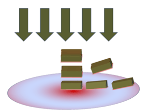
The process works like this: First, a precursor gas (A) is introduced into the process chamber, where it adsorbs onto all available substrate sites. No further adsorption occurs once all surface sites are occupied. An inert purge gas, typically nitrogen or argon, flushes out any remaining precursor gas, then a second precursor (B) is introduced. Precursor B reacts with the chemisorbed precursor A to produce the desired film. Once all of the adsorbed molecules are consumed, the reaction stops. After a second purge step, the cycle repeats.
ALD opportunities expand as features shrink
The step-by-step nature of ALD is both its strength and its weakness. Depositing one monolayer at a time gives manufacturers extremely precise thickness control. Using different precursor gases in different ratios can tune the film composition. Unfortunately, the repeated precursor/purge gas cycles take a lot of time. In an interview, CEA-Leti researcher Rémy Gassilloud estimated that in a single wafer process, two minutes per wafer is the maximum cost-effective process time. But two minutes is only enough time to deposit about a 2nm-thick film.
Some process adjustments can improve throughput. Silicon dioxide ALD often uses large furnaces to process many wafers at once. Plasma activation can ionize reagents and accelerate film formation. Still, Gassilloud estimates that 10nm is the maximum practical thickness for ALD films.
As transistors shrink, though, the number of layers in that thickness range is increasing. Transistor structures also are becoming more complex, requiring deposition on vertical surfaces, into deep trenches, and other places not readily accessible by line-of-sight PVD methods. Replacement gates for gate-all-around transistors, for instance, need a process that can fill nanometer-scale cavities.
As noted above, HfO2 was the first successful application of ALD in semiconductor manufacturing. Its precursors, HfCl4 and water, are both chemically simple small molecules, whose by-products are volatile and easily removed. Such simple chemistries are the exception, though. ALD of silicon dioxide typically uses aminosilane precursors.[1] Metal nitrides often have complex metal-organic precursor gases. Gassilloud noted that ligands might be added to a precursor molecule to change its vapor pressure or reactivity, or to facilitate adhesion to the substrate. In selective deposition processes, discussed below, ligands might improve selectivity between growth and non-growth surfaces. These larger molecules can be difficult to insinuate into smaller features, and byproducts can be difficult to remove. Complex byproducts can also become a contamination source.
One of the advantages of ALD is its very low process temperature, typically between 200°C and 300°C. It is thermally compatible with both transistor and interconnect processes in CMOS, as well as with deposition on plastic and other novel substrates. Even so, Aditya Kumar and colleagues at GlobalFoundries showed that precise temperature control is important.[2] TDMAT (tetrakis- dimethylamino titanium) condensation in a TiN deposition process was a significant source of particle defects. To maintain the desired process temperature, both the precursor and purge gas temperatures matter. Introducing cold purge gas into a warm process chamber can cause rapid condensation.
As ALD has become a mainstream process, the industry has found applications for it beyond core device materials, in a variety of sacrificial and spacer layers. For example, double- and quadruple-patterning schemes often use ALD for “pitch-doubling.” By depositing a spacer material on either side of a patterned “mandrel,” then removing the mandrel, the process can cut the original pitch in half without the need for an additional, more costly lithography step.[3]
![]()
Fig. 1: Self-aligned double patterning with ALD spacers. Source: Creative Commons
Depositing a doped oxide on the vertical silicon fins of a finFET device is a less directional and less damaging alternative to ion implantation.[4]
Selective deposition brings lateral control
These last two examples depend on surface characteristics to mediate deposition. A precursor might adhere more readily to a hard mask than to the underlying material. The vertical face of a silicon fin might offer more (or fewer) adsorption sites than the horizontal face. Selective deposition on more complicated structures may require a pre-deposited growth template, functionalizing substrate regions to encourage or discourage growth. Selective deposition is especially important in interconnect applications. In general, though, a comprehensive review by Rong Chen and colleagues at Huazhong University of Science and Technology explained that selective deposition methods need to replenish the template material as the film grows while needing a mechanism to selectively remove the unwanted material.[5]
For example, tungsten preferentially deposits on silicon relative to SiO2, but the selectivity diminishes after only a few cycles. Researchers at North Carolina State University successfully re-passivated the oxide by incorporating hydrogen into the tungsten precursor.[6] Similarly, a group at Eindhoven University of Technology found that SiO2 preferentially deposited on SiO2 relative to other oxides for only 10 to 15 cycles. A so-called ABC-cycle — adding acetylacetone (“Inhibitor A”) as an inhibitor every 5 to 10 cycles — restored selectivity.[7]
Alternatively, or in addition, atomic layer etching (ALE) might be used to remove unwanted material. ALE operates in the same step-by-step manner as ALD. The first half of a cycle reacts with the existing surface, weakening the bond to the underlying material. Then, a second step — typically ion bombardment — removes the weakened layer. For example, in ALE etching of silicon, chlorine gas reacts with the surface to form various SiClx compounds. The chlorination process weakens the inter-silicon bonds between the surface and the bulk, and the chlorinated layer is easily sputtered away. The layer-by-layer nature of ALE depends on preferential removal of the surface material relative to the bulk (SiClx vs. Si in this case). The “ALE window” is the combination of energy and temperature at which the surface layer is completely removed without damaging the underlying material.
Somewhat counter-intuitively, Keren Kanarik and colleagues at Lam Research found that higher ion energies actually expanded the ALE window for silicon etching. High ion energies with short exposure times delayed the onset of silicon sputtering relative to conventional RIE.[8]
Adding and subtracting, one atomic layer at a time
For a long time, the semiconductor industry has been looking for alternatives to process schemes that deposit material, pattern it, then etch most of it away. Wouldn’t it be simpler to only deposit the material we will ultimately need? Meanwhile, atomic layer deposition has been filling the spaces under nanosheets and inside cavities. Bulk deposition and etch tools are still with us, and will be for the foreseeable future. In more and more cases, though, those tools provide the frame while ALD and ALE processes fill in the details.
Correction: Corrected attribution of the work on ABC cycles and selective deposition of SiO2.
References
- Wenling Li, et al., “Impact of aminosilane and silanol precursor structure on atomic layer deposition process,”Applied Surface Science, Vol 621, 2023,156869, https://doi.org/10.1016/j.apsusc.2023.156869.
- Kumar, et al., “ALD TiN Surface Defect Reduction for 12nm and Beyond Technologies,” 2020 31st Annual SEMI Advanced Semiconductor Manufacturing Conference (ASMC), Saratoga Springs, NY, USA, 2020, pp. 1-4, doi: 10.1109/ASMC49169.2020.9185271.
- Shohei Yamauchi, et al., “Extendibility of self-aligned type multiple patterning for further scaling”, Proc. SPIE 8682, Advances in Resist Materials and Processing Technology XXX, 86821D (29 March 2013); https://doi.org/10.1117/12.2011953
- Kalkofen, et al., “Atomic layer deposition of phosphorus oxide films as solid sources for doping of semiconductor structures,” 2018 IEEE 18th International Conference on Nanotechnology (IEEE-NANO), Cork, Ireland, 2018, pp. 1-4, doi: 10.1109/NANO.2018.8626235.
- Rong Chen et al., “Atomic level deposition to extend Moore’s law and beyond,” 2020 Int. J. Extrem. Manuf. 2 022002 DOI 10.1088/2631-7990/ab83e0
- B Kalanyan, et al., “Using hydrogen to expand the inherent substrate selectivity window during tungsten atomic layer deposition,” 2016 Chem. Mater. 28 117–26 https://doi.org/10.1021/acs.chemmater.5b03319
- Alfredo Mameli et al., “Area-Selective Atomic Layer Deposition of SiO2 Using Acetylacetone as a Chemoselective Inhibitor in an ABC-Type Cycle” ACS Nano 2017, 11, 9, 9303–9311. https://doi.org/10.1021/acsnano.7b04701
- Keren J. Kanarik, et al., “Universal scaling relationship for atomic layer etching,” J. Vac. Sci. Technol. A 39, 010401 (2021); doi: 10.1116/6.0000762
The post Enabling Advanced Devices With Atomic Layer Processes appeared first on Semiconductor Engineering.